1
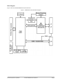
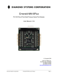
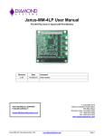
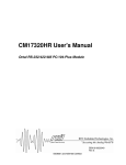
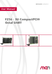
Emerald-MM-8Plus
PC/104-Plus 8-Port Multi-Protocol Serial Port Module
User Manual v1.03
© Copyright 2006
Diamond Systems Corporation
1255 Terra Bella Ave.
Mountain View, CA 94043
Tel (650) 810-2500
Fax (650) 810-2525
www.diamondsystems.com
Table of Contents
Introduction......................................................................................................................4
Description and Features...........................................................................................4
Block Diagram............................................................................................................5
Board Description.......................................................................................................6
Connector Summary..................................................................................................7
Jumper Summary.......................................................................................................7
Connectors.......................................................................................................................8
PC/104 ISA Bus.........................................................................................................8
PC/104-Plus PCI Bus.................................................................................................9
I/O Header Connectors............................................................................................10
RS-232 Pin Assignment...................................................................................... 11
RS-485 Pin Assignment...................................................................................... 12
RS-422 Pin Assignment...................................................................................... 13
Digital I/O and Counter/timer Connector..................................................................14
Board Configuration......................................................................................................15
Serial Protocol Selection..........................................................................................15
RS-232 Selection.................................................................................................16
RS-422 Selection.................................................................................................16
RS-485 Selection.................................................................................................17
PCI Slot ID Selection...............................................................................................18
EEPROM Programming.................................................................................................19
Serial Communication...................................................................................................20
Serial Port Operation...............................................................................................20
Line Termination......................................................................................................20
Digital I/O and Counter/Timer.......................................................................................21
Specifications.................................................................................................................22
Serial Ports...............................................................................................................22
Digital I/O.................................................................................................................22
General....................................................................................................................22
Additional Information..................................................................................................23
Technical Support..........................................................................................................24
Diamond Systems Corporation
Emerald-MM-8Plus User Manual
Page 2
Figures
Figure 1: EMM-8Plus Functional Block Diagram...............................................................5
Figure 2: EMM-8Plus Board Layout.................................................................................. 6
Figure 3: PC/104 ISA Bus Connectors - J1, J2.................................................................8
Figure 4: PC/104-Plus PCI Connector - J3........................................................................9
Figure 5: I/O Header Connectors - J4, J5........................................................................10
Figure 6: RS-232 Protocol Selection...............................................................................16
Figure 7: RS-422 Protocol Selection Options..................................................................16
Figure 8: RS-485 Protocol Selection Options..................................................................17
Figure 9: PCI Slot ID Selection Jumper...........................................................................18
Figure 10: Line Termination Schematics.........................................................................20
Diamond Systems Corporation
Emerald-MM-8Plus User Manual
Page 3
Introduction
Emerald-MM-8Plus is a PC/104-Plus module with four or eight serial ports connected through the PCI bus. Each
port supports RS-232, RS-422, RS-485 and 5V TTL interfaces using jumper configuration. The board also has eight
digital I/O lines and a 16-bit counter/timer.
Emerald-MM-8Plus is connector compatible with the Emerald-MM-8P, Emerald-MM-8M, and Emerald-MM-8232
boards. It is compatible with all Diamond Systems Corporation CPUs with PC/104-Plus connectors. The board is
intended to be compatible with any CPU with a PC/104-Plus expansion socket and operates with both 3.3V and 5V
PCI I/O voltage buses.
Description and Features
Two I/O headers are provided, with four serial ports on each header. The board operates on +5V only, eliminating
the need for a +12V supply that is often required for serial port operation.
Emerald-MM-8Plus is based on the Exar XR17D158IV Octal UART. This device contains eight identical sets of
registers, one set for each port. The registers are compatible with the standard PC serial port. Each port contains a
64-byte FIFO.
The Emerald-MM-8Plus has the following features.
•
•
•
•
•
•
•
•
•
•
•
•
•
•
•
I/O connectors compatible with Emerald-MM-8P (two connectors, 40 pins, four ports per connector).
Eight serial ports based on Exar XR17D158IV Octal UART with 64-byte FIFOs.
RS-232, RS-422, RS-485, and TTL interfaces supported: RS-232/422/485 jumper selectable; TTL available as
a custom assembly configuration.
Baud rates to 921.6Kbps in RS-232 or TTL mode, 1.8432Mbps in RS-422/RS-485 modes.
Jumper-selected protocol and line termination.
EEPROM storage of configuration data for instant availability on power-up.
I/O lines are short circuit protected.
Eight digital I/O lines with 5V logic.
LED connected to digital I/O line 0.
Programmable counter/timer with selectable clock source.
Dual 40-pin I/O headers, 4 ports per header.
+5V only operation.
Extended temperature (-40 to +85°C) operation.
PC/104-Plus form factor.
Stackthrough PC/104 and PC/104-Plus connectors installed.
Refer to the Exar XR17D158IV datasheet, listed in the Additional Information section of this document, for
detailed information about using the UART, DIO and EEPROM functionality with the PC/104-Plus bus.
Diamond Systems Corporation
Emerald-MM-8Plus User Manual
Page 4
Block Diagram
Figure 1 shows the Emerald-MM-8Plus functional blocks.
Figure 1: EMM-8Plus Functional Block Diagram
Diamond Systems Corporation
Emerald-MM-8Plus User Manual
Page 5
Board Description
Figure 2 shows the Emerald-MM-8Plus board connectors and jumpers.
Figure 2: EMM-8Plus Board Layout
Diamond Systems Corporation
Emerald-MM-8Plus User Manual
Page 6
Connector Summary
The following tables list the Emerald-MM-8Plus board connectors.
Connector
Description
J1
PC/104, ISA bus A,B
Manufacturer Part No.
EPT 962-60323-12
J2
PC/104, ISA bus C,D
EPT 962-60203-12
J3
PC/104-Plus PCI bus connector
-
J4
Serial ports 1-4
J5
Serial ports 5-8
J15
Digital I/O and counter/timer
Jumper Summary
The following table lists the Emerald-MM-8Plus jumpers.
Jumper
J6
Description
PCI bus slot selection.
J7-J10
Serial port configuration (Serial ports 1-4, respectively).
J11-J14
Serial port configuration (Serial ports 5-8, respectively).
Diamond Systems Corporation
Emerald-MM-8Plus User Manual
Page 7
Connectors
This section describes the connectors on the Emerald-MM-8Plus board.
PC/104 ISA Bus
Connectors J1 and J2 carry the ISA bus signal. Figure 3 shows the PC/104 A and B pin layout for J1, and the C and
D pin layout for J2. These signals are not used to communicate with the CPU but are pass to other cards on the
PC/104 stack.
Figure 3: PC/104 ISA Bus Connectors - J1, J2
J1 Connector Pinout
IOCHCHKSD7
SD6
SD5
SD4
SD3
SD2
SD1
SD0
IOCHRDY
AEN
SA19
SA18
SA17
SA16
SA15
SA14
SA13
SA12
SA11
SA10
SA9
SA8
SA7
SA6
SA5
SA4
SA3
SA2
SA1
SA0
GND
A1
A2
A3
A4
A5
A6
A7
A8
A9
A10
A11
A12
A13
A14
A15
A16
A17
A18
A19
A20
A21
A22
A23
A24
A25
A26
A27
A28
A29
A30
A31
A32
Diamond Systems Corporation
B1
B2
B3
B4
B5
B6
B7
B8
B9
B10
B11
B12
B13
B14
B15
B16
B17
B18
B19
B20
B21
B22
B23
B24
B25
B26
B27
B28
B29
B30
B31
B32
J2 Connector Pinout
GND
RESETDRV
+5V
IRQ9
-5V
DRQ2
-12V
ENDXFR+12V
keyed
SMEMWSMEMRIOWIORDACK3DRQ3
DACK1DRQ1
REFRESHSYSCLK
IRQ7
IRQ6
IRQ5
IRQ4
IRQ3
DACK2TC
BALE
+5V
OSC
GND
GND
GND
SBHELA23
LA22
LA21
LA20
LA19
LA18
LA17
MEMRMEMWSD8
SD9
SD10
SD11
SD12
SD13
SD14
SD15
keyed
Emerald-MM-8Plus User Manual
C0
C1
C2
C3
C4
C5
C6
C7
C8
C9
C10
C11
C12
C13
C14
C15
C16
C17
C18
C19
D0
D1
D2
D3
D4
D5
D6
D7
D8
D9
D10
D11
D12
D13
D14
D15
D16
D17
D18
D19
GND
MEMCS16-IOCS16IRQ10
IRQ11
IRQ12
IRQ15
IRQ14
DACK0DRQ0
DACK5DRQ5
DACK6DRQ6
DACK7DRQ7
+5
MASTERGND
GND
Page 8
PC/104-Plus PCI Bus
The PC/104-Plus bus is essentially identical to the PCI Bus except for the physical design. A single pin and socket
connector is specified for the bus signals. A 120-pin header, J3, arranged as four 30-pin rows incorporates a full 32bit, 33MHz PCI Bus. The additional pins on the PC/104-Plus connectors are used as ground or key pins. The
female sockets on the top of the board enable stacking another PC/104-Plus board on top of the Emerald-MM-8Plus
board. The Emerald-MM-8Plus board should be the bottom board of a PC/104-Plus stackup.
In the connector J3 pinout table, below, the top corresponds to the left edge of the connector when the board is
viewed from the primary side (the side with the female end of the PC/104-Plus connector), and the board is oriented
so that the PC/104 connectors are along the bottom edge of the board and the PC/104-Plus connector is in the top of
the Emerald-MM-8Plus board.
Figure 4: PC/104-Plus PCI Connector - J3
1
2
3
4
5
6
7
8
9
10
11
12
13
14
15
16
17
18
19
20
21
22
23
24
25
26
27
28
29
30
A
GND/5.0V KEY
VI/O
AD05
C/BE0*
GND
AD11
AD14
+3.3V
SERR*
GND
STOP*
+3.3V
FRAME*
GND
AD18
AD21
+3.3V
IDSEL0
AD24
GND
AD29
+5V
REQ0*
GND
GNT1*
+5V
CLK2
GND
+12V
-12V
Diamond Systems Corporation
B
Reserved
AD02
GND
AD07
AD09
VI/O
AD13
C/BE1*
GND
PERR*
+3.3V
TRDY*
GND
AD16
+3.3V
AD20
AD23
GND
C/BE3*
AD26
+5V
AD30
GND
REQ2*
VI/O
CLK0
+5V
INTD*
INTA*
~REQ3
C
+5V
AD01
AD04
GND
AD08
AD10
GND
AD15
Reserved
+3.3V
LOCK*
GND
IRDY*
+3.3V
AD17
GND
AD22
IDSEL1
VI/O
AD25
AD28
GND
REQ1*
+5V
GNT2*
GND
CLK3
+5V
INTB*
~GNT3
Emerald-MM-8Plus User Manual
D
AD00
+5V
AD03
AD06
GND
M66EN
AD12
+3.3V
PAR
Reserved
GND
DESEL*
+3.3V
C/BE2*
GND
AD19
+3.3V
IDSEL2
IDSEL3
GND
AD27
AD31
VI/O
GNT0*
GND
CLK1
GND
RST*
INTC*
GND/3.3V KEY
Page 9
On the Emerald-MM-8Plus, the octal UART is connected to the PCI bus and is powered by 5V with its PCI
interface powered by the PCI bus VIO, which can be 3.3V or 5V. For this reason, the connector is not keyed (to
prevent certain types of cards from being inserted).
I/O Header Connectors
Emerald-MM-8Plus provides two identical 40-pin headers labeled J4 and J5 for the serial ports. Four ports are
contained on each header.
Figure 5: I/O Header Connectors - J4, J5
Connector, J4,is for ports 1-4 and is located along the right side of the board.
J4 Port No.
PORT1
Pin Assignment
Pins 1 - 10
PORT2
Pins 11 - 20
PORT3
Pins 21 - 30
PORT4
Pins 31 - 40
Connector, J5, is for ports 5-8 and is located along the left side of the board.
J5 Port No.
PORT5
Pin Assignment
Pins 1 - 10
PORT6
Pins 11 - 20
PORT7
Pins 21 - 30
PORT8
Pins 31 - 40
Pin numbers are marked on the board to assist with connector orientation.
Diamond Systems Corporation Cable Assembly Number C-DB9M-4 connects this header to four DE-9 Male
connectors, for direct connection to RS-232-C signaling. The following tables list the signals for the appropriate
mode of operation, as well as the DE-9 pin numbers to which these signals are wired.
Diamond Systems Corporation
Emerald-MM-8Plus User Manual
Page 10
RS-232 Pin Assignment
J4
Port1:
Port2:
Port3:
Port4:
J5
DCD1
1
2
DSR1
RXD1
3
4
RTS1
TXD1
5
6
DTR1
7
8
DCD5
1
2
DSR5
RXD5
3
4
RTS5
CTS1
TXD5
5
6
CTS5
RI1
DTR5
7
8
RI5
GND
9
10
DIO0
DCD2
11
12
DSR2
RXD2
13
14
RTS2
Port5:
Port6:
GND
9
10
DIO4
DCD6
11
12
DSR6
RXD6
13
14
RTS6
TXD2
15
16
CTS2
TXD6
15
16
CTS6
DTR2
17
18
RI2
DTR6
17
18
RI6
GND
19
20
DIO1
DCD3
21
22
DSR3
RXD3
23
24
RTS3
Port7:
GND
19
20
DIO5
DCD7
21
22
DSR7
RXD7
23
24
RTS7
TXD3
25
26
CTS3
TXD7
25
26
CTS7
DTR3
27
28
RI3
DTR7
27
28
RI7
GND
29
30
DIO2
DCD4
31
32
DSR4
RXD4
33
34
RTS4
Port8:
GND
29
30
DIO6
DCD8
31
32
DSR8
RXD8
33
34
RTS8
TXD4
35
36
CTS4
TXD8
35
36
CTS8
DTR4
37
38
RI4
DTR8
37
38
RI8
GND
39
40
DIO3
GND
39
40
DIO7
Signal
DCDn
Definition
Data Carrier Detect
DE-9 Pin
pin 1
Direction
Input
DSRn
Data Set Ready
pin 6
Input
RXDn
Receive Data
pin 2
Input
RTSn
Request to Send
pin 7
Output
TXDn
Transmit Data
pin 3
Output
CTSn
Clear to Send
pin 8
Input
DTRn
Data Terminal Ready
pin 4
Output
RIn
Ring Indicator
pin 9
Input
GND
Ground
pin 5
Signal Ground
DIOn
Digital I/O
-
-
Diamond Systems Corporation
Emerald-MM-8Plus User Manual
Page 11
RS-485 Pin Assignment
J4
Port1:
J5
NC
1
2
NC
TXD/RXD+1
3
4
TXD/RXD-1
NC
5
6
NC
7
8
GND
9
10
DIO0
NC
11
12
NC
TXD/RXD+2
13
14
TXD/RXD-2
NC
15
16
NC
17
18
GND
19
20
DIO1
NC
21
22
NC
TXD/RXD+3
23
24
TXD/RXD-3
NC
25
26
NC
27
28
GND
29
30
DIO2
NC
31
32
NC
TXD/RXD+4
33
34
TXD/RXD-4
NC
35
36
NC
37
38
GND
39
40
DIO3
Port2:
Port3:
Port4:
Port5:
NC
1
2
NC
TXD/RXD+5
3
4
TXD/RXD-5
NC
NC
5
6
NC
NC
NC
7
8
NC
GND
9
10
DIO4
NC
11
12
NC
TXD/RXD+6
13
14
TXD/RXD-6
NC
NC
15
16
NC
NC
NC
17
18
NC
GND
19
20
DIO5
NC
21
22
NC
TXD/RXD+7
23
24
TXD/RXD-7
NC
NC
25
26
NC
NC
NC
27
28
NC
GND
29
30
DIO6
NC
31
32
NC
TXD/RXD+8
33
34
TXD/RXD-8
NC
NC
35
36
NC
NC
NC
37
38
NC
GND
39
40
DIO7
Port6:
RXD6
Port7:
Port8:
Signal
TXD/RXD+n
Definition
Differential Transceiver Data (HIGH)
DE-9 Pin
pin 2
Direction
bi-directional
TXD/RXD-n
Differential Transceiver Data (LOW)
pin 7
bi-directional
GND
Ground
pin 5
Signal Ground
NC
(not connected)
-
-
DIOn
Digital I/O
-
-
Diamond Systems Corporation
Emerald-MM-8Plus User Manual
Page 12
RS-422 Pin Assignment
J4
Port1:
Port2:
Port3:
Port4:
J5
NC
1
2
NC
TXD+1
3
4
TXD-1
NC
5
6
RXD-1
RXD+1
7
8
NC
GND
9
10
DIO0
NC
11
12
NC
TXD+2
13
14
TXD-2
NC
15
16
RXD-2
RXD+2
17
18
NC
GND
19
20
DIO1
NC
21
22
NC
TXD+3
23
24
TXD-3
NC
25
26
RXD-3
RXD+3
27
28
NC
GND
29
30
DIO2
NC
31
32
NC
TXD+4
33
34
TXD-4
NC
35
36
RXD-4
RXD+4
37
38
NC
GND
39
40
DIO3
Port5:
NC
1
2
NC
TXD+5
3
4
TXD-5
NC
5
6
RXD-5
RXD+5
7
8
NC
GND
9
10
DIO4
NC
11
12
NC
TXD+6
13
14
TXD-6
Port6:
NC
15
16
RXD-6
RXD+6
17
18
NC
GND
19
20
DIO5
NC
21
22
NC
TXD+7
23
24
TXD-7
Port7:
NC
25
26
RXD-7
RXD+7
27
28
NC
GND
29
30
DIO6
NC
31
32
NC
TXD+8
33
34
TXD-8
Port8:
NC
35
36
RXD-8
RXD+8
37
38
NC
GND
39
40
DIO7
Signal
TXD+n/TXD-n
Definition
Differential transmit data
DE-9 Pin
pin 2/pin 7
Direction
Output*
RXD+n/RXD-n
Differential receive data
pin 4/pin 8
Input*
GND
Ground
pin 5
Signal Ground
NC
(not connected)
-
-
DIOn
Digital I/O
-
-
(* Separate lines)
Diamond Systems Corporation
Emerald-MM-8Plus User Manual
Page 13
Digital I/O and Counter/timer Connector
Connector J15 is a 1x10, single-row, right-angle connector that provides the following digital I/O and counter/timer
signals.
Signal
DIO 0-7
1
DIO7
2
DIO5
3
DIO3
4
DIO1
5
Counter/timer In
2
DIO 6
4
DIO 4
6
DIO 2
8
DIO 0/Counter/timer Out/LED Out
10
GND
Definition
Digital I/O; programmable direction
Counter/timer In
Counter/timer input
Counter/timer Out Counter/timer output
LED Out
GND
Diamond Systems Corporation
User-defined LED, typically for board status
Ground
Emerald-MM-8Plus User Manual
Page 14
Board Configuration
The board provides jumper blocks to configure the following functions.
•
•
•
•
Serial port protocol RS-232/422/485/TTL: 2 positions for each port.
RS-422/485 RX and TX termination: 4 positions for each port.
RS-485 echo yes/no per port: 1 position for each port.
PCI slot ID: 2 positions for slot 0-3 selection.
For hardwired configuration, locations are provided on the PCB for 0-ohm resistors to be installed to replace each
valid jumper position.
Serial Protocol Selection
Jumper blocks J7 through J14 are used to select the protocol for each serial port, as shown in the table below. Each
jumper block configures one port, and each port may have its protocol set independently of the other ports.
Jumper
J7
Port
1
J8
2
J9
3
J10
4
J11
5
J12
6
J13
7
J14
8
In RS-422 or RS-485 networks, termination resistors are normally installed at the endpoints of the cables to
minimize reflections on the lines. Emerald-MM-8Plus provides 150Ω resistors for this purpose. To enable resistor
termination for a port, install jumpers in the locations T and R of that port’s corresponding configuration jumper
block as shown, below.
Note: Termination is only needed, and should only be used, at the cable endpoints. Enabling these
termination resistors at each end of the cable results in an effective impedance of 60Ω. Installing
termination resistors at additional points in the network may cause overloading and failure of the
line drivers due to the lower impedance caused by multiple resistors in parallel.
In RS-422 or RS-485 networks, biasing resistors are normally installed at the endpoints of the cables to force a
known inactive state on the lines to reduce noise and eliminate line float by pulling the Data+ line to +5V and the
Data- line to ground. Emerald-MM-8Plus provides 4.7KΩ resistors for this purpose. To enable resistor termination
for a port, install jumpers in the locations B of that port’s corresponding configuration jumper block as shown above.
For RS422 networks the RX termination always has biasing resistors connected when used and the TX termination
has the biasing resistor connections optional when used.
Note: Biasing is only needed, and should only be used, at one of the cable endpoints. Installing
biasing resistors at additional points in the network may cause overloading and failure of the line
drivers due to the lower impedance caused by multiple resistors in parallel.
Diamond Systems Corporation
Emerald-MM-8Plus User Manual
Page 15
RS-232 Selection
Figure 6 shows the J7 through J14 jumper settings to select the RS-232 protocol. (No pins are jumpered).
Figure 6: RS-232 Protocol Selection
RS-422 Selection
Figure 7 shows the J7 through J14 jumper settings to select the RS-422 protocol options.
Figure 7: RS-422 Protocol Selection Options
Diamond Systems Corporation
Emerald-MM-8Plus User Manual
Page 16
RS-485 Selection
Figure 8 shows the J7 through J14 jumper settings to select the RS-485 protocol options.
Figure 8: RS-485 Protocol Selection Options
Diamond Systems Corporation
Emerald-MM-8Plus User Manual
Page 17
PCI Slot ID Selection
Jumper block J6 sets the PCI slot ID using two jumpers, as shown in Figure 9. Take care in selecting the correct
PCI slot to avoid resource conflicts in the software driver.
Figure 9: PCI Slot ID Selection Jumper
Diamond Systems Corporation
Emerald-MM-8Plus User Manual
Page 18
EEPROM Programming
Emerald-MM-8P has a 256-byte EEPROM, of which the lowest 64 bytes are addressable. The first eight locations
are used to store the PCI vendor and device IDs, and the remaining bytes are available for user-defined functions.
EEPROM Address
Function
0
PCI Vendor ID, low byte
1
PCI Vendor ID, high byte
2
PCI Device ID, low byte
3
PCI Device ID, high byte
4
PCI Subsystem Vendor ID, low byte
5
PCI Subsystem Vendor ID, high byte
6
PCI Subsystem Device ID, low byte
7
PCI Subsystem Device ID, high byte
8-63
User-defined
Refer to the Exar Corporation datasheet for the XR17D158 UART, listed in the Additional Information section of
this document, for EEPROM programming procedures.
Diamond Systems Corporation
Emerald-MM-8Plus User Manual
Page 19
Serial Communication
Eight serial ports are provided by the XR17D158 octal PCI UART chip. The input clock is driven by a
14.7456MHz crystal.
Serial Port Operation
Each port can be independently configured for RS-232, RS-422, RS-485 or TTL interface using jumpers or
assembly options. RS-232 and TTL are mutually exclusive due to signal level incompatibility. If one transceiver is
installed for a port, the other set is not. The standard configuration is RS-232/422/485 transceivers installed. Ports 1
through 4, or 5 through 8, can be configured for TTL line levels as a custom assembly option. Contact Diamond
Systems for custom configuration options.
Transceiver control is managed using the eight identical 2x8 jumper blocks, J7-J14.
In RS-485 mode, both local ECHO and NO ECHO modes are supported. In local echo mode the receiver is always
on. In no echo mode, the receiver and transmitter are enabled alternately so that no echo is received during
transmission. The output transceiver can be automatically enabled/disabled by setting a control bit in the modem
status register (MSR) of the XR17D158. This causes RTS to automatically turn on before transmission starts and
turn off after transmission ends. Use MSR bits to program the transmitter disable delay after last bit transmission.
The RS-232 and RS-422/485 transceivers have built-in ESD protection. The TTL transceivers do not have ESD
protection, however, they serve as protection for the UART in TTL mode.
Line Termination
In RS-422 and RS-485 modes, 150-ohm, 0.25 watt termination resistors may be connected across the differential
transceiver lines with jumpers. (One for transmit pair, one for receive pair in RS-422, one only for RS-485).
All UART port inputs have pull-up/pull-down resistors to force the inputs to their inactive state when the RS-422 or
RS-485 protocol is selected. All TTL inputs have pull-up/pull-down resistors to force them to their inactive state
when unconnected.
All RS-422/485 inputs have jumper-selectable pull-up/pull-down (bias) resistors to force them to their inactive states
when unconnected. The pull-up/pull-down resistors must be high enough to prevent a false signal due to the voltage
divider resulting from the pull-up, pull-down and line termination resistors (50mV threshold). See the example
schematics for line termination and bias resistors, below.
Figure 10: Line Termination Schematics
Diamond Systems Corporation
Emerald-MM-8Plus User Manual
Page 20
Digital I/O and Counter/Timer
The XR17D158 UART offers 8 built-in digital I/O lines and a programmable counter/timer. The 8 DIO lines and the
counter/timer signals are brought out to an 8-pin connector on the lower edge of the board.
The DIO and counter/timer signals are 3.3V nominal logic signals and have ESD protection.
The 8 DIO lines are also available on the 8 extra pins on the two serial I/O connectors to provide compatibility with
EMM-8P. The user must be made aware of the limitation that only one source can be used for input, either the serial
port connector or the dedicated DIO connector.
The counter/timer’s output is multiplexed under software control to DIO 0. The counter/timer’s input is
programmable for either an internal clock or an external signal. The external signal is available on a pin on the
digital I/O connector.
DIO 0 has an LED connected to it for use in displaying board activity or health status.
Diamond Systems Corporation
Emerald-MM-8Plus User Manual
Page 21
Specifications
Serial Ports
•
•
•
•
•
No. of serial ports: 8
Protocols: RS-232, RS-422, RS-485
Maximum baud rate: 921.6Kbps (RS-232), 1.832Mbps (RS-422/RS-485)
Communications parameters: 5, 6, 7, or 8 data bits; even, odd, or no parity
Short circuit protection: All outputs protected against continuous short circuit
RS-232 mode
•
•
•
Input impedance: 3KΩ min
Input voltage swing: ±30V max
Display type: ±5V min, ±7V typical
RS-422/RS-485 modes
•
•
•
•
•
Differential input threshold: -0.2V min, +0.2V max
Input impedance: 12KΩ min
Input current: +1.0mA max (VIN = 12V)
-0.8mA max (VIN = -7V)
Differential output voltage: 2.0V min (RL = 50Ω)
High/low states differential output voltage symmetries: 0.2V max
Digital I/O
No. of I/O lines: 8 in, 8 out
Input voltage: Low: -0.3V min, 0.8V max
High: 2.0V min, 5.3V max
• Output voltage: Low: 0.0V min, 0.4V max (IOL = 6mA max)
High: 3.7V min, 5.0V max (IOH = -4mA max)
•
•
General
•
•
•
•
•
•
•
Dimensions: 3.55” x 3.775” LxW (PC/104 standard)
Power supply: +5VDC ±10%
Current consumption: 160mA typical, all outputs unloaded
Operating temperature: -40° to +85° C
Operating humidity: 5% to 95% non-condensing
PC/104 bus: 8-bit and 16-bit bus headers are installed and used (16-bit header is used for interrupt levels only)
I/O header: 2 40-position (2x20) .025” square pin header on .1” centers;
Headers mate with standard ribbon cable (IDC) connectors
Diamond Systems Corporation
Emerald-MM-8Plus User Manual
Page 22
Additional Information
Additional information can be found at the following websites.
1. Diamond Systems Corporation (http://www.diamondsystems.com/)
2. Datasheet, XR17D158 Universal (3.3V and 5V) PCI Bus Octal UART, Exar Corporation, August 2005. (.pdf)
Diamond Systems Corporation
Emerald-MM-8Plus User Manual
Page 23
Technical Support
For technical support, please email [email protected] or contact Diamond Systems Corporation
technical support at 1-650-810-2500.
Diamond Systems Corporation
Emerald-MM-8Plus User Manual
Page 24