1
Cutting Data
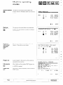
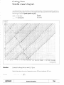
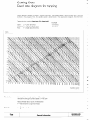
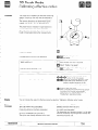
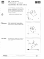
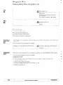
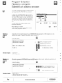
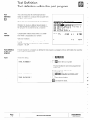
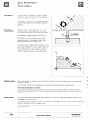
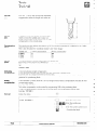
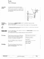
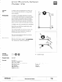
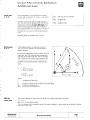
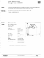
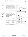
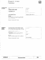
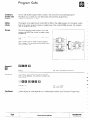
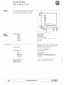
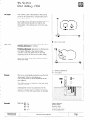
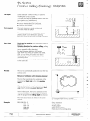
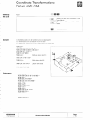
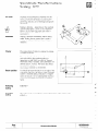
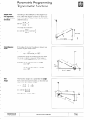
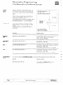
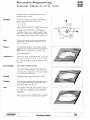
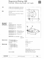
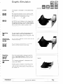
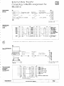
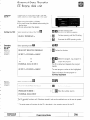
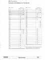
Feed rate diagram
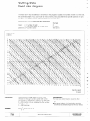
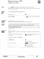
The feed rate F must be defined In [mm/min]
in the program. Usually, the number of teeth n on the tool,
the permitted depth of cut d per tooth (in mm) and the previously determined
spindle speed S (in rpm)
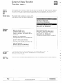
are given. The diagram below helps you determine the feed rate F.
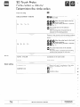
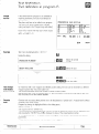
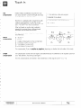
Determine
Given:
Selected:
Find:
the required
n
d
S
F
=
=
=
=
feed
rate F in [mm/min]
number of teeth
permitted depth of cut per tooth
spindle speed
feed rate
Example
6
0.1 [mm]
500 [rpm]
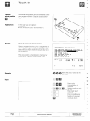
Depth of cut
d [mm1
Spindle
speed
S [wml
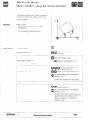
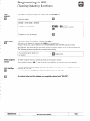
Calculation
Horizontal line through depth of cut 0.1 mm
Vertical line through spindle soeed 500 m/min
At the point of intersection, read off the feed rate
F = 50 mm/min; this is multiplred by the number
of teeth n = 6:
F = 300 mm/min
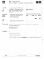
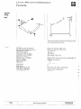
d=
Formula
Page
A 20
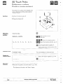
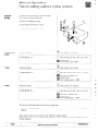
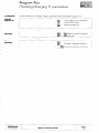
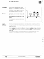
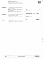
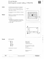
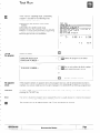
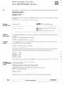
Prerequisites:
The feed rate determination
assumes that
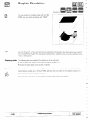
l the tool axis infeed = l/2 tool radius
or
l the lateral infeed = l/4 tool radius and the
downfeed is selected equal to the tool radius
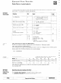
F
-orF=d.S.n
S.n
1
General
Information
HEIDENHAIN
TNC 2500B
-