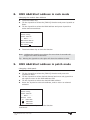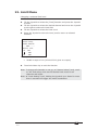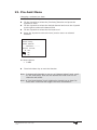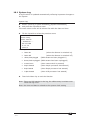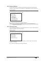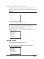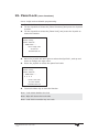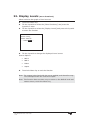
1
ART2000S User Manual
related to software version
system build: Jan 06 05
LCD : V1.0/1.5/1.0
HOT:1.1/1.1/1.0
PDE: 0.1
Last document update 05-01-05
Stock number 8200-0162
*82000162*
Useful Avolites phone numbers:Avolites England
Sales and service*
(+44) (0) 20 8965 8522
Service out of hours*(+44) (0) 831 17 8888
Fax
(+44) (0) 20 8965 0290
Email
[email protected]
Website
http://www.avolites.com
Distribution of Avolites products in USA:Avolites America
Sales and service*
(+1) 423 938 2057
Fax
(+1) 423 938 2059
*Before contacting Avolites for service enquiry please ensure that you have the
product serial number and the Software version (shown at switch on).
The latest version of this manual (MS Word 2000 & PDF) and ART2000
Software can be downloaded from the Internet.
The small print :
No Liability for Consequential Damages
Avolites has a policy of continuous product and documentation improvement. As such the
detail within this manual may not match the operation of the ART2000s.
In no event shall Avolites be liable for any direct, indirect, special, incidental, or consequential
damages or loss whatsoever (including, without limitation, damages for loss of profits,
business interruption, or other pecuniary loss) arising out of the use or inability to use the
ART2000s even if Avolites Ltd. has been advised of the possibility of such damages. Because
some jurisdictions do not allow the exclusion or limitation of liability for consequential or
incidental damages, the above limitation may not apply to you.
Reprint and revision history:
First produced Jan 2004 by J.B.Toby
Early adopters version June 2004 by J.B.Toby
First release Sept 2004 by J.B.Toby
Updated for software changes Jan 2005 J.B.Toby
Jan. 17 Created from menu structure document
June. 18 functions done, Press changed to Touch
June. 22 proofread, typos, Limit function corrected
June. 23 early adopters release of doc and dimmer
Sept. 20 release of doc and dimmer added general dimmer text
Jan. 07 updated for software changes, elaborated on menus
Aug 05 RS Minor page layout changes
A2Ks-Manual-Rev1a.doc 29.01.2008
14:47
C O N T E N T S
1.
THE ART2000S MANUAL
4
2.
IMPORTANT SAFETY INFORMATION
4
3.
CONNECTIONS TO THE DIMMER
5
4.
MAINS CONTROLS ON THE DIMMER
6
5.
THE USER INTERFACE
6
6.
MAIN FUNCTION LIST
7
7.
MORE FUNCTIONS LIST
9
8.
DMX A&B START ADDRESS IN RACK MODE
10
9.
DMX A&B START ADDRESS IN PATCH MODE
10
10. DMX ADDRESS MODE
11
11. CURVE MENU
12
12. LIMIT MENU
13
13. PRE-HEAT MENU
14
14. MEMORY STORE
15
15. FADERS MODE
16
16. MEMORY REPLAY
17
17. CHANNEL TEST
17
18. SYSTEM INFORMATION (MORE FUNCTIONS)
18
19. PANEL LOCK (MORE FUNCTIONS)
24
20. PANEL UNLOCK
25
21. UNLOCK DMX (MORE FUNCTIONS)
25
22. DISPLAY LEVELS (MORE FUNCTIONS)
26
23. USER SETTINGS (MORE FUNCTIONS)
27
24. WIPE ALL (MORE FUNCTIONS)
28
25. CLOCK (MORE FUNCTIONS)
29
26. SOFTWARE VERSION (MORE FUNCTIONS)
30
27. SOFTWARE UPGRADE (MORE FUNCTIONS)
31
28. MAINS STATUS (MORE FUNCTIONS)
32
29. SOFTWARE LIMITATIONS
32
30. APPENDIX- CONNECTOR WIRING
33
A2Ks-Manual-Rev1a.doc 29.01.2008
14:47
1.
The ART2000s Manual
This manual is designed to help you get the most out of your Avolites
ART2000 digital dimming system. Even if you hate reading manuals,
read this section because the next couple of pages contain some
important safety information which you should be aware of.
1.1
The ART2000S
The ART2000s module is a self-contained dimmer unit
The ART2000s controls up to 12 channels. The following module types
are currently available:
x
12 channel 16Amp dimming module
x
6 channel 32Amp dimming module (available Q3 2005)
The LCD on the front provide a wealth of information on the dimmer
state such as “Load Check” and “fuse fail indicators for each dimmer
channel. Each channel can be set-up separately with a curve, A limit
and two start address for the two DMX inputs. The user interface
consists of a large backlit LCD screen, a joystick and two touch sensitive
switches
Other features are: two isolated and floating DMX inputs, 12 faders for
local and memory control and lastly an optional 30mA RCB unit.
2.
Important safety information
This system uses 3-phase power and can be a serious hazard to
health and other equipment.
This manual is however not an electrical safety manual.
The system should be installed and operated only by a competent
person. When installing you should check local regulations regarding the
separation of lighting fixtures on different phases (see also appendix
One Phase per multipin Outlet). If you are in any doubt as to the safe
installation of the system you should employ the services of a qualified
electrical contractor.
Do not operate the system with any dimmer parts or panels missing
because this makes live parts accessible.
Before turning on the ART2000S, ensure that the Mains is connected
correctly. The system may be damaged if it is turned on with the power
feed connected incorrectly.
A2Ks-Manual-Rev1a.doc 29.01.2008
14:47
3.
Connections to the dimmer
3.1
Mains
The dimmer is connected to mains grid with a trailing cable. This cable
can be single phase or 3 phase depending on the unit’s configuration.
See appendix for cable colours and connections.
In case of a three phase unit, You need to provide a three phase and
neutral power supply to the ART2000s (TN-S) which is capable of
delivering the amount of power required to run all the lights which are
connected to it. If the power supply is under-rated it may trip during
your show if you turn too many lights on at once. This is obviously not a
good thing to happen. Also, an overloaded mains supply can suffer from
a distorted waveform which can make it difficult for the ART module to
control your lights smoothly.
Warning: Never use mains supplied with “reduced neutral” cable sizes,
as dimmers inherently dump large currents in the neutral
connection. These kind of mains supplies are sometimes called
“industrial” and are not suitable for dimmer applications.
When ordering or specifying a mains supply state that it is for “phase
angle controlled light dimming”
The frequency of the mains is automatically tracked by the system,
which makes the ART system suitable for use on local generator sets.
3.2
Channel Outlets
The dimmer channel outlets are on the back, the type of connector used
depends on the unit’s configuration. When two multipin connectors are
fitted the left most (see from the back) will be channels 1-6 or 1-3
See appendix for connections and pin numbers.
3.3
DMX data connection
The DMX is connected using standard 5 pin XLR connectors on the right
hand front panel. The left most pair is Line A in, and loop out and the
right most pair is Line B in, and loop out.
Both DMX lines are isolated from each other and floating from the
dimmer chassis. A 2M resistance is present between Pin 1 and the
dimmer chassis to allow for save static discharge when connecting the
DMX system.
When the dimmer is the last in line fit a 120R termination plug in the
loop out of the used DMX input.
Do not fit a termination plug if the DMX input is not used.
See appendix for connections and pin numbers.
A2Ks-Manual-Rev1a.doc 29.01.2008
14:47
4.
Mains Controls on the dimmer
The ART2000S can be fitted with a 30mA RCB breaker
Resetting the RCB
ÎRotate the RCB reset Lever on the left front of the dimmer module
Note: If the RCB is reset the Lever can move free up and down
Note: if the RCB is tripped the Lever is held down by the RCB
Important note:
As with any RCB breaker, Test the RCB frequently by using the Red RCB
test switch located on the front.
Do not use the RCB as an ON/OFF switch as this will reduce the RCB
contact life
5.
The User Interface
The ART2000s uses two touch sensitive switches and a Joystick with an
integral Enter switch as user interface
The joystick works in the Up/Down and Left/Right direction. To enter a
function or accept a selection press the Joystick knob when it is in the
neutral position (no tilt or side ways movement)
The screen is a 128x64 pixels Graphics LCD, and supports 8x21
characters, which are custom defined. A bulb with animated light rays is
used as a “hart beat” indicator
(not shown in this document screen examples)
Typical screen after power-up:
0 A 001 0 B 002
Status: running
Faders: faders on
--------------------OOOOOOOOO O O 0
1 2 3 4 5 6 7 8 9 10 11 12
The status line indicates the mode the system is in,
System Status modes:
5.1
x
Running OK
(normal operation mode)
x
Warning
(see System log for details)
x
Reset
(after power up and manual reset)
Menu and Screen Time-out rules
Functions time out, screen views do not, so if a DMX menu is up, it will
time-out after about 40 seconds.
Continued…
A2Ks-Manual-Rev1a.doc 29.01.2008
14:47
The following screens and modes do not time out
x
x
x
5.2
Default Level and Status screen
Exclusive Level screen, selected by the user
Diagnostics screen
Information screens
The following information screens are available
x Channel status and bar graph (default screen)
x Channel level exclusive from the different sources
x clock
x Software version
After power-up the A2Ks will always use the Channel status and bar
graph screen as top level screen.
6.
Main Function List
The ART2000s uses two menu layers. To minimize the need to scroll
trough large lists, the day to day functions are contained in the “main
function” list. And the specialist and rarely used functions are contained
in the “more functions” list
ÎTouch the Menu Key
ÎTilt the Joystick to scroll to function and Enter the function by
pressing the joystick
Note: A short description of the function is given on the LCD below the
menu selection
0 A 001 0 B 002
Status: running
Faders: faders on
-------MENU-------DMX A
Values
. Set DMX A
Relating to current
DMX A address mode
Functions
x
Help
x
DMX A
x
DMX B
x
DMX address mode
x
Curve
x
Limit
x
Pre-heat
x
memory store
x
Fader Mode
x
More Functions...
ÎTouch the Menu key to return to the default level screen
A2Ks-Manual-Rev1a.doc 29.01.2008
14:47
Continued..
A2Ks-Manual-Rev1a.doc 29.01.2008
14:47
Note: After a power-up or reset, pressing the Menu key will start the
menu at the [Help] screen, tilting the joystick down will bring
[DMX A] function up.
Note: During runtime the menu starts at the point of the last function
entry
Note: The menu tree can be scrolled up (Tilting the joystick up) or
scrolled down (Tilting the joystick down).
7.
More Functions List
Specialist and rarely used functions are contained in the “more
functions” list
ÎTouch the Menu Key
ÎTilt the Joystick to scroll to [More Functions] and enter by pressing
the joystick
ÎTilt the Joystick to select the desired function and enter by pressing
the joystick
0 A 001 0 B 002
Status: running
Faders: faders on
-------MORE------Settings .
Wheel to change
Turn
Press wheel to select
Touch MENU to exit
Functions
o
Panel Lock
o
Unlock DMX
o
Display Levels
o
User settings
o
Clock
o
Software Version
o
Software Upgrade
o
Mains Status
o
Wipe all
o
System information
ÎTouch the Menu key to return to the default level screen
Note: During runtime the menu starts at the point of the last function
entry both in the main function tree and in the More function
tree.
TIP: To re-enter a function from the More functions tree, simply touch
the Menu key and press the Joystick twice.
A2Ks-Manual-Rev1a.doc 29.01.2008
14:47
8.
DMX A&B Start address in rack mode
Changing the module Start Address
ÎTouch the Menu Key
ÎTilt the Joystick to select the [DMX-A] function and press Joystick to
Enter
ÎTilt the Joystick to select the DMX address and press Joystick to
select and save address
0 A 001 0 B 002
Status: running
Faders: faders on
----- DMX A --------DMX A Start Address
Current Address 001
New address 001
ÎTouch the Menu key to exit the function
Note: Holding the joystick up or down for more than 3 seconds will
trigger the value acceleration
Tip: Moving the joystick to the right will clear the address to 000
9.
DMX A&B Start address in patch mode
Changing a DMX patch
ÎTouch the Menu Key
ÎTilt the Joystick to select the [DMX-A] function and press the
Joystick to Enter
ÎTilt the Joystick to select desired channel and move the joystick to
the right to move to the DMX address field
ÎTilt the Joystick to select the desired DMX address
ÎPress the Joystick to save the address, and to return to channel
selection
0 A 001 0 B 002
Status: running
Faders: faders on
----- DMX A --------Channel
All
Patch
DMX A 000
01
DMX A 002
02
DMX A 003
ÎTouch the Menu key to exit the function
Continued…
A2Ks-Manual-Rev1a.doc 29.01.2008
14:47
Note: To load a “1:1 patch”, at “channel select” level, scroll to “All” and
select by moving the joystick to the address value then set the
desired DMX Start Address for the module to start from (dimmer
channel 1) and select.
Note: DMX address 000 parks a channel
Note: for US style patching (all channels parked) use channel select “All”
and select DMX 000, then patch desired channels.
Note: At “DMX” level, holding the joystick up or down for more than 3
seconds will trigger the value acceleration
10. DMX Address Mode
Changing the DMX address mode
ÎTouch the Menu Key
ÎTilt the Joystick to select the [DMX Address Mode] function and
press the Joystick to Enter
ÎTilt the Joystick to select desired DMX input move the joystick to the
right to select the address mode field
0 A 001 0 B 002
Status: running
Faders: faders on
-- DMX ADRESS MODE -Line
Mode
DMX A Start Address
DMX B Start Address
ÎTilt the Joystick to change to the desired patch mode and Press the
Joystick to select
0 A 001 0 B 002
Status: running
Faders: faders on
--DMX ADRESS MODE -Line
Mode
DMX A Start Address
DMX B Patch
ÎTouch the Menu key to exit the function
Note: The Patch data is retained when the DMX address mode is
changed from Patch to Start Address
Note: The Start Address is retained when the DMX address mode is
changed from Start address to Patch
Note: Use the [wipe all] function to clear both the patch and the start
address and default the dimmer to start address 001
A2Ks-Manual-Rev1a.doc 29.01.2008
14:47
11. Curve Menu
Changing a selected curve
ÎTouch the Menu Key
ÎTilt the Joystick to select the [Curve] function and press the Joystick
to enter
ÎTilt the Joystick to select the desired channel and move the Joystick
to the right to select Curve field
ÎTilt the Joystick to select the desired Curve
ÎPress the Joystick to save the curve, and to return to channel
selection
0 A 001 0 B 002
status: running
Faders: faders on
------ CURVE -------Channel Curve
All
linear
04
relay 50%
05
inv relay
Curve options
x
Linear
x
Relay
x
invert relay
x
Square
x
Desk Defined
ÎTouch the Menu key to exit the function
Note: To change all channels in one go, at “channel select” level, scroll
to “All” and select, then set the desired Curve for all channels and
select.
Note: Use “Desk defined” if a curve is set up in the console. This
prevents the two curves affecting each other.
A2Ks-Manual-Rev1a.doc 29.01.2008
14:47
12. Limit Menu
Changing a selected limit level
ÎTouch the Menu Key
ÎTilt the Joystick to select the [Limit] function and press the Joystick
to enter
ÎTilt the Joystick to select the desired channel and move the Joystick
to the right to select the Limit field
ÎTilt the Joystick to select the Limit Level
ÎPress the Joystick to save the Level, and to return to channel
selection
0 A 001 0 B 002
Status: running
Faders: faders on
----- LIMIT --------Channel Limit
All
80%
04
100%
05
100%
Limit options
x
10-90% in steps of 1% (A limit 0f 0% gives no output)
ÎTouch the Menu key to exit the function
Note: To change all channels in one go, at “channel select” level, scroll
to “All” and select, then set the desired Limit Level for all
channels and select.
Note: at “Limit Setting” level, holding the joystick up or down for more
than 3 seconds will trigger the value acceleration
A2Ks-Manual-Rev1a.doc 29.01.2008
14:47
13. Pre-heat Menu
Changing a selected pre-heat
ÎTouch the Menu Key
ÎTilt the Joystick to select the [Pre-heat] function and press the
Joystick to enter
ÎTilt the Joystick to select the desired channel and move the Joystick
to the right to select the channel field
ÎTilt the Joystick to select the Pre-heat Level
ÎPress the Joystick to save the Level, and to return to channel
selection
0 A 001 0 B 002
Status: running
Faders: faders on
-------PRE-HEAT------------Channel Pre-heat
All 10%
04
0%
05
0%
Pre-Heat options
x
0-100%
ÎTouch the Menu key to exit the function
Note: To change all channels in one go, at “channel select” level, scroll
to “All” and select, then set the desired Pre-heat Level for all
channels and select.
Note: at “pre-heat Setting” level, holding the joystick up or down for
more than 3 seconds will trigger the value acceleration
A2Ks-Manual-Rev1a.doc 29.01.2008
14:47
14. Memory Store
Storing a memory
ÎBuild a look either using the locals faders or under DMX control
ÎTouch the Menu Key
ÎTilt the Joystick to select the [Store Memory] function and press the
Joystick to enter
ÎTilt the Joystick to select the desired memory location and move the
Joystick to the right to select the store field
0 A 001 0 B 002
Status: Running
Faders: Faders On
---MEMORY STORE --Memory Store
12
local
01
local
02
local
memory options
x
Memory 1-12
ÎTilt the Joystick to select type of store command (Local or Global)
and press the Joystick to store and return to the memory location
select level
0 A 001 0 B 002
Status: Running
Faders: Faders On
---MEMORY STORE --Memory Store
12
local
01
global
02
local
Store command options
x
Local to this dimmer
x
Global to all (command send to Other ART2000 dimmers)
ÎTouch the Menu key to exit the function
Note: Both Local and Global store command stores a memory on this
dimmer
Note: “Local” only the local dimmer stores a memory
Note: “Global” downstream Avolites ART dimmers will also store the
selected memory
A2Ks-Manual-Rev1a.doc 29.01.2008
14:47
15. Faders Mode
Changing the fader mode
ÎTouch the Menu Key
ÎTilt the Joystick to select the [Fader Mode] function and press the
Joystick to enter
ÎTilt the Joystick to select the desired Faders Mode and press the
Joystick to select
0 A 001 0 B 002
Status: running
Faders: faders on
--- FADERS MODE ----Replay
Faders will control channels in
memories
Fader Mode options
x
replay (a single faders can control 12 channels)
x
Test
x
Master (Be aware that the console will be disconnected!!)
(each fader controls one channel)
ÎTouch the Menu key to exit the function
Note: “Replay mode” allows for one fader to control the all the module
channels
Note: “Test Mode” each faders controls the corresponding channel, this
is the default mode after a reset and power-up
Note: “Master Mode” The dimmer can trigger memories on downstream
connected Avolites ART dimmers. Be aware console will be
disconnected
Note: Changing to Replay and Master will force the faders off to prevent
accidental high inrush currents
Note: If the dimmer receives DMX from an ART2000i, memory 12 may
be triggered if the ART2000i frame is set to the “Panic” mode.
A2Ks-Manual-Rev1a.doc 29.01.2008
14:47
16. Memory Replay
Replaying a memory
Îcheck that the LCD screen shows: Faders: Replay Off if not see Fader
Mode function
ÎTouching the Fader key toggles the replay mode on and off
0 A 001 0 B 002
status: running
Faders: Replay On
--------------------
17. Channel Test
Replaying a memory
Îcheck that the LCD screen shows: Faders: Test Off if not see Fader
Mode function
ÎTouching the Fader key toggles the faders on and off
0 A 001 0 B 002
Status: running
Faders: Test On
--------------------
A2Ks-Manual-Rev1a.doc 29.01.2008
14:47
18. System Information
(more functions)
System setup and diagnostic information regarding the system are
contained in this menu.
System information
ÎTouch the Menu Key
ÎTilt the Joystick to select the [More Functions] and press the Joystick
to enter
0 A 001 0 B 002
Status: running
Faders: faders on
-- MORE FUNCTIONS --System Information
Display system log, serial
numbers, and diagnostics
ÎTilt the Joystick to select [System Information] function and press
the Joystick to select enter
0 A 001 0 B 002
Status: running
Faders: faders on
-SYSTEM INFORMATIONSerial number
ÎTilt the Joystick to select the desired subject and press the Joystick
to see the data
Information subjects:
x
System log
x
System status
(system resource monitor )
x
Flicker finder
(a test tool to detect flicker)
x
Serial number (hardware serial number)
x
RDM ID
x
IP address
x
IP subnet mask
x
IP gateway
x
MAC address
(list of system events)
(unique ID for ESTA RDM communications)
(IP network address)
(unique ID for Ethernet MAC)
ÎTouch the Menu key to exit the function
Note: The serial number, RDM ID and MAC address are factory set and
cannot be changed by the user. When referring to a dimmer
always use the serial number, which is also copied on the back of
the dimmer unit
The individual Information sources are detailed below….
A2Ks-Manual-Rev1a.doc 29.01.2008
14:47
18.1 System Log
A log file which is updated automatically reflecting important changes to
the system
System Log
ÎSelect System Log in [more functions],[System information]
Îand press the Joystick to enter
The most recent event will be shown first with the date and time
ÎTilt the Joystick to select the previous event
0 A 001 0 B 002
Status: running
Faders: faders on
--- SYSTEM LOG ----18th June 2004
12 : 26 : 20
power on
Event options
x
Power On
(when the dimmer is switched on)
x
Power Off
(when the dimmer is switched off)
x
dmxa,dmxb plugged
x
dmxa,dmxb unplugged (DMX stream has been unplugged)
x
manual reset
(when reset switch is pressed)
x
hotpic booted
(when hotpic processor has started )
x
Dspic booted
(when Dspic processor has started)
x
Lcdpic booted
(when LCD processor has started)
(DMX stream as been plugged in)
ÎTouch the Menu key to exit the function
Note: There are 256 entries in the log, the oldest entry is written over
when the log is full.
Note: the time and date is related to the system clock setting
A2Ks-Manual-Rev1a.doc 29.01.2008
14:47
18.2 System Status
A timer and memory counter are presented showing the used system
memory of the system (not related to or dependant on user memories)
System Status
ÎSelect System Status in [more functions],[System information]
Îand press the Joystick to enter
0 A 001 0 B 002
Status: running
Faders: faders on
-- SYSTEM status --Seconds 000001
Max 321472 bytes
Free Ram 321472 bytes
Min 321472 bytes
ÎTouch the Menu key to exit the function
Note: This is an engineering/debug screen, no user information is
contained in this screen
18.3 Flicker Finder
A tool to detect instability in the data stream, this may be used to detect
flicker from DMX sources and faders
Flicker finders
ÎSelect Flicker Finder in [more functions],[System information]
Îand press the Joystick to enter
0 A 001 0 B 002
Status: running
Faders: faders on
- Flicker Finder --Non flicker detected
When a change is detected of more than 1 bit the finder will stop and
display a message
ÎTouch the Menu key to exit the function
A2Ks-Manual-Rev1a.doc 29.01.2008
14:47
18.4 Serial Number
Shows unique serial number of the dimmer.
Serial Number
ÎSelect Serial Number in [more functions],[System information]
Îand press the Joystick to enter
0 A 001 0 B 002
Status: running
Faders: faders on
-- Serial Number ---003.000.000.000.000
ÎTouch the Menu key to exit the function
18.5 RDM ID
Shows unique ESTA assigned RDM ID. This ID cannot be changed by the
user.
RDM ID
ÎSelect RDM ID in [more functions],[System information]
Îand press the Joystick to enter
0 A 001 0 B 002
Status: running
Faders: faders on
---- RDM ID -----077.086.003.000.000
ÎTouch the Menu key to exit the function
A2Ks-Manual-Rev1a.doc 29.01.2008
14:47
18.6 IP Address, IP mask and Gateway
Shows the current IP address of the dimmer module when an Ethernet
card is detected. And the IP address can be changed in this menu
Only the IP address is given as an example, IP mask and Gateway follow
the same operation.
IP address
ÎSelect IP Address in [more functions],[System information]
Îand press the Joystick to enter
0 A 001 0 B 002
Status: running
Faders: faders on
--- IP address ----Display
192.168.000.001
ÎTouch the Menu key to exit the function
Changing the IP address, IP Mask and Gateway
When in the [IP address] function:
ÎTilt the Joystick to select the [Set] and press the Joystick to enter
ÎMove the Joystick left or right to select the desired field
ÎTilt the joystick to change the value
ÎPress the joystick to save the new system IP address
Only the IP address is given as an example, IP mask and Gateway follow
the same operation.
0 A 001 0 B 002
Status: running
Faders: faders on
--- IP address ----Set
192.168.000.001
ÎTouch the Menu key to exit the function
18.7 MAC address
Shows unique Ethernet MAC address when an Ethernet card is detected
This Address cannot be changed by the user.
MAC Address
ÎSelect MAC address in [more functions],[System information]
Îand press the Joystick to enter
0 A 001 0 B 002
Status: running
Faders: faders on
--- Mac Address ----00.00.00.00.00.00
A2Ks-Manual-Rev1a.doc 29.01.2008
14:47
ÎTouch the Menu key to exit the function
A2Ks-Manual-Rev1a.doc 29.01.2008
14:47
19. Panel Lock
(more functions)
Use a 4 digit code to disable programming
ÎTouch the Menu Key
ÎTilt the Joystick to select the [More Functions] and press the Joystick
to enter
ÎTilt the Joystick to select the [Panel Lock] and press the Joystick to
enter the function
0 A 001 0 B 002
Status: running
Faders: faders on
--- PANEL LOCK ----Use a 4 digit code
To lock out
Unauthorised use
ÎMove the joystick left and right to select the digit field , and up and
down to change the digit value.
ÎPress the joystick to select the panel lock code
0 A 001 0 B 002
Status: running
Faders: faders on
--- PANEL LOCK ----0 0 0 0
Enter a lock code
Or enter 0 0 0 0
To disable the lock
ÎTouch the Menu key to exit the function
Note: Code 0000 disables the lock
Note: Wipe All clears the Lock code
Note: code 2000 overrides any set code
A2Ks-Manual-Rev1a.doc 29.01.2008
14:47
20. Panel Unlock
Gaining access when the panel lock is active
ÎTouch the Fader or Menu Key
ÎMove the joystick left and right to select the digit field, and up and
down to change the digit value to the set code.
ÎPress the joystick unlock
0 A 001 0 B 002
Status: running
Faders: faders on
--- PANEL UNLOCK ---0 0 0 0
Panel is locked
Please Enter the code
Note: when activated (code non zero) the panel locks automatically after
1 minute of no user input
Note: code 2000 overrides any set code
21. Unlock DMX
(more functions)
Fade out locked DMX levels after a DMX stream has stopped
ÎTouch the Menu Key
ÎTilt the Joystick to select the [More Functions] and press the
Joystick to enter
ÎTilt the Joystick to select the [Unlock DMX] and press the Joystick to
enter the function
0 A 001 0 B 002
Status: running
Faders: faders on
---- UNLOCK DMX ---Fade Out the locked DMX? Press
Joystick to unlock
Touch Menu to exit
Îpress the Joystick to unlock the locked DMX
ÎTouch the Menu key to exit the function
Note: the Unlock function fades out locked channels with a 5 seconds
fade
A2Ks-Manual-Rev1a.doc 29.01.2008
14:47
22. Display Levels
(more functions)
Show exclusive bar graph of level sources
ÎTouch the Menu Key
ÎTilt the Joystick to select the [More Functions] and press the
Joystick to enter
ÎTilt the Joystick to select the [Display Levels] and press the Joystick
to enter the function
0 A 001 0 B 002
Status: running
Faders: faders on
-----LEVELS DMX A ---
ÎTilt the Joystick to change the displayed Level source
Source Options
x
DMX A
x
DMX B
x
Faders
x
Output
ÎTouch the Menu key to exit the function
Note: The output is the level with the curve applied, and therefore may
not correspond with the console’s output
Note: This function does not time out, to return to the default level and
status screen, touch the Menu key
A2Ks-Manual-Rev1a.doc 29.01.2008
14:47
23. User Settings
(more functions)
Allows the User to set system configurations like DMX source and time
format
ÎTouch the Menu Key
ÎTilt the Joystick to select the [More Functions] and press the
Joystick to enter
ÎTilt the Joystick to select the [User settings and press the Joystick to
enter the function
0 A 001 0 B 002
Status: running
Faders: faders on
-----User settings--Time format = 24 hr
A source = DMX512
B source = DXM512
ÎTilt the Joystick to select the setting to be changed
Îpress the Joystick to change the setting
ÎTilt the Joystick to change the setting
Îpress the Joystick to change the setting
ÎTouch the Menu key to exit the function
Time options:
x
24 hr
x
12 hr (am/pm)
A&B source options:
x
DMX512
x
ARTNet
Note: The source can only be changed if an Ethernet card has been
detected, in all other cases the data inputs are defaulted to
DMX512 data streams
A2Ks-Manual-Rev1a.doc 29.01.2008
14:47
24. Wipe All
(more functions)
Clear User settings, and load default values
ÎTouch the Menu Key
ÎTilt the Joystick to select the [More Functions] and press the
Joystick to enter
ÎTilt the Joystick to select the [Wipe all] and press the Joystick to
enter the function
0 A 001 0 B 002
Status: running
Faders: faders on
-----WIPE ALL ------Clear all User Data
Press Joystick to select
Touch Menu to exit
ÎTouch the Menu key to exit the function
Note: Default values are
DMX A and B Start Address 001, module patch mode
All Channels have a Linear Curve selected
All Channels have the Limit is reset to 0%
All channels the pre/heat reset to 0%
All memories are cleared
Panel Lock is unlocked
Note: The system log cannot be cleared
A2Ks-Manual-Rev1a.doc 29.01.2008
14:47
25. Clock
(more functions)
Showing System Clock and Date
ÎTouch the Menu Key
ÎTilt the Joystick to select the [More Functions] and press the
Joystick to enter
ÎTilt the Joystick to select the [Clock] and press the Joystick to enter
the function
0 A 001 0 B 002
Status: running
Faders: faders on
-----CLOCK ------Display
18th June 2004
16: 27 : 11
ÎTouch the Menu key to exit the function
Changing System Clock and Date
When in the [Clock] function:
ÎTilt the Joystick to select the [Set] and press the Joystick to enter
ÎMove the Joystick left or right to select the desired field
ÎTilt the joystick to change the value
ÎPress the joystick to save the new system clock and date settings
0 A 001 0 B 002
Status: running
Faders: faders on
-----CLOCK ------Set
18th June 2004
16: 27 : 11
ÎTouch the Menu key to exit the function
A2Ks-Manual-Rev1a.doc 29.01.2008
14:47
26. Software version
(more functions)
Showing the various software versions
ÎTouch the Menu Key
ÎTilt the Joystick to select the [More Functions] and press the Joystick
to enter
ÎTilt the Joystick to select the [Software Version] and press the
Joystick to enter the function
0 A 001 0 B 002
Status: running
Faders: faders on
- SOFTWARE VERSION -System
June 17th 2004
11:58:38
ÎTilt the Joystick to select the different hardware modules and display
the loaded version
Hardware module Options
x
System
(main controller)
x
HotPIC
(Load and breaker detect)
x
lcdPIC
(Fader and touch switches)
x
DSPIC
(dimming engine)
ÎTouch menu to exit the function
Note: if the hardware module is not connected, or the module is not
communicating, no software version can be displayed
Note: Use these version numbers, along with the serial number of the
unit to report to the Avolites service department
A2Ks-Manual-Rev1a.doc 29.01.2008
14:47
27. Software Upgrade
(more functions)
Updating the various software systems
ÎConnect the D9 connector of the Upload cable to a serial port on a
windows PC with the upgrade software installed
ÎConnect the mini DIN to the Upgrade port on the left side panel
ÎTouch the Menu Key
ÎTilt the Joystick to select the [More Functions] and press the
Joystick to enter
ÎTilt the Joystick to select the [Software Upgrade] and press the
Joystick to enter the function
0 A 001 0 B 002
Status: running
Faders: faders on
- SOFTWARE UPGRADE -burn System software
Press Joystick to start
Touch menu to exit
ÎTilt the Joystick to select the desired hardware module and press the
Joystick to select
ÎOn the PC click on the “UPLOAD” button
0 A 001 0 B 002
Status: running
Faders: faders on
- SOFTWARE UPGRADE burn HotPIC software
Start Upload Program Address
0x000
Hardware module Options
x
System
(main controller)
x
HotPIC
(Load and breaker detect)
x
lcdPIC
(Fader and touch switches)
x
DSPIC
(dimming engine)
ÎPress RESET to exit at this stage and after a successful program
session
Note: The windows upgrade program will not allow you to burn the
wrong software in the wrong hardware system
Note: A detailed manual for both the windows program and the upgrade
procedure will be provided with the upgrade software
Note: check software version after each upgrade to verify burn success
A2Ks-Manual-Rev1a.doc 29.01.2008
14:47
28. Mains Status
(more functions)
Show the mains system parameters
ÎTouch the Menu Key
ÎTilt the Joystick to select the [More Functions] and press the
Joystick to enter
ÎTilt the Joystick to select the [Mains Status] and press the Joystick
to enter the function
0 A 001 0 B 002
Status: running
Faders: faders on
-- MAINS STATUS ----
Î Touch the Menu key to exit the function
29. Software limitations
Below is a list of known limitations for system build: Jan 06 05
29.1 System software
[More functions] > [Mains Status] is not implemented; see also PDEDSP limitations.
29.2 Known User Interface Quirks
None
29.3 LCD-PIC software limitations
None
29.4 HOT-PIC software limitations
A loaded channel at full shows up as “No Load ” (open circle)
29.5 PDE-DSP software limitations
No Mains data talkback to System controller (user interface).
No Version data talkback to System controller (user interface).
3Phase+N WYE supply by default, single phase trough Jumper setting
A2Ks-Manual-Rev1a.doc 29.01.2008
14:47
30. Appendix- Connector Wiring
30.1 Mains colours
30.1.1
Connection tail
Type
PE
neutr
al
Phase 1
Phase 2
Phase 3
3 phase
Green/Yellow
Blue
Brown
Black
Black
Single phase
Green/Yellow
30.1.2
Internal mains colours
PE
Neutral
Phase 1
Phase 2
Phase 3
Green/Yellow
Black
Red
Yellow
Blue
30.2 Multipin connections
30.2.1
Socapex standard
Phase
neutral
Channel 1
1
2
Channel 2
3
4
Channel 3
5
6
Channel 4
7
8
Channel 5
9
10
Channel 6
11
12
PE
13,14,15,16,17,18,19
Channel allocation on back of the panel
Not fitted
30.2.2
CH. 1-6
CH. 7-12
Harting 1-2
Phase
neutral
Channel 1
1
2
Channel 2
3
4
Channel 3
5
6
Channel 4
7
8
Channel 5
9
10
Channel 6
11
12
Optional PE
13,14,15,16
PE
Harting side tab
A2Ks-Manual-Rev1a.doc 29.01.2008
14:47
Not fitted
Channel allocation on back of the panel
Not fitted
CH. 1-6
30.2.3
CH. 7-12
Not fitted
Harting 1-9
Phase
neutral
Channel 1
1
9
Channel 2
2
10
Channel 3
3
11
Channel 4
4
12
Channel 5
5
13
Channel 6
6
14
Optional PE
7,8,15,16
PE
Harting side tab
Channel allocation on back of the panel
Not fitted
CH. 1-6
CH. 7-12
Not fitted
30.3 DMX pin data
30.3.1
Connector allocation
DMX A in
DMX A Loop-out
DMX B in
DMX B Loop-out
30.3.2
DMX pins
Pin 1
Floating ground 2M resistance between pin and chassis
Pin 2
- Data
Pin 3
+ data
Pin 4
Wire linked between” in” and” Loop-out”
Pin 5
Wire linked between” in” and” Loop-out
A2Ks-Manual-Rev1a.doc 29.01.2008
14:47
30.4 Mains connections
Use supplied ferrules for 10mm2
cables, if thinner cable is used fit
appropriate ferrule
PE connection Point, assure that
three (3) internal PE wires are
connected , Use supplied Nyloc nut
Use torque screw driver to set RCB
screws to 2 N/m
PE
Phase L2
Phase L1
Phase L3
optional RCB
Phase L3
Neutral
RCB Neutral
Fit RCB neutral fork under clamp
screw. do NOT fit with feed wire
Avolites ART2000s
mains connenction guide
A2Ks-Manual-Rev1a.doc 29.01.2008
14:47
Phase L2
optional RCB
Phase L1
Neutral
RCB Neutral