1
TEC-B-01 User Manual
____________________________________________________________________________________________________________________________
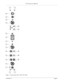
(1)
MODE OF OPERATION switch
Switch to select the MODE OF OPERATION:
VC:
OFF:
CC:
Voltage Clamp
In this position the current injection of the amplifier is switched OFF, e.g. for
operating the bridge amplifier as stand-alone device
Current Clamp with current injection through the current headstage
Note: In CC operation the current stimulus input of the bridge amplifier is used!
EXT.:
POWER OFF:
EXTernal control. For operating the TEC-B-01 amplifier as a constant current
source, e.g. for iontophoresis, or for operating the bridge amplifier as stand-alone
device
Power is turned OFF
(2)
GAIN VC potentiometer
10-turn potentiometer to set amplification factor (GAIN) of the VC error signal. To keep the VC error
as small as possible it is necessary to use high GAIN settings, but the system becomes unstable and
begins to oscillate if the GAIN is set too high.
(3)
Rs COMP. potentiometer
10-turn potentiometer to set the amount of series resistance compensation. Series resistance
compensation improves the performance of the clamp system, especially if fast voltage-activated
currents are recorded.
Important: Series resistance compensation is done by positive feedback in the control circuit, which
can lead very quickly to stability problems. Therefore, tuning of the series resistance compensation has
to be carried out with great care!
(4)
CURRENT FILTER (Hz) switch
6-position switch to set the corner frequency of the CURRENT FILTER (100, 300, 500, 1k, 3k or
5k Hz) available at #17.
(5)
CUR. OUTP. SENS. (V/µA) switch
Switch to set the amplification of the current signal at #17 (1 V / µA, 10 V / µA, 100 V / µA).
(6)
HOLDING POTENTIAL potentiometer
10-turn potentiometer for setting the HOLDING POTENTIAL in VC mode
(7)
+ /0 /- switch
Switch for setting the polarity of the HOLDING POTENTIAL in VC mode. In 0 position the
HOLDING POTENTIAL is disabled, i.e. set to 0 mV.
(8)
DUAL LED
LED indicating operation with the a bridge amplifier in CC or VC mode.
__________________________________________________________________________________
version 1.0
page 6