1
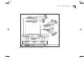
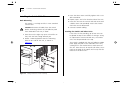
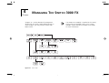
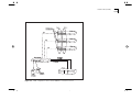
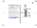
2-6
CHAPTER 2: INSTALLATION AND SETUP
Powering-Up the Switch
1 Connect the power cord to the IEC socket on the
rear of the Switch, and to your mains socket.
The Switch has no ON/OFF switch; the only method
of connecting or disconnecting mains power is
through the power cord.
2 The Switch enters a Power On Self Test (POST). The
time taken for the test to complete is dependent
on the type of POST configured. (Refer to “Switch
Management Setup” on page 3-9 for details of how
to configure the type of POST.) For a new Switch
that is being installed for the first time, power-up
takes approximately 15 seconds.
3 Check the status LEDs to ensure the Switch is oper-
ating correctly (refer to “LEDs” on page 1-9).
Connecting a Redundant Power System (RPS)
You can connect a Redundant Power System (RPS)
to the Switch.
At +5V, the current requirement for the Switch is
4.8A, including any Transceiver Module that might
be fitted, but excluding a Plug-in Module. Check the
documentation supplied with your Plug-in Module
for power consumption figures.
For most configurations, you only need one SuperStack II RPS output, and this can be connected to
either of the two sockets on the rear of the unit.
If the current consumption of the Switch plus any
optional Plug-in Module exceeds the capability of
the RPS (8.5A), you need a SuperStack II Advanced
RPS with one Advanced RPS 100W Module.
If the RPS is used incorrectly, its Output Fault LED
lights yellow.
You should check the documentation supplied with
the RPS or Advanced RPS to see if the outputs can
be used in parallel.