1
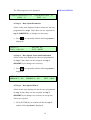
7.0 Typical Machine Cycle
EXPLANATIONS:
7.1 Component Setting
•
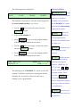
Place the component under the stylus in the same
position as before.
•
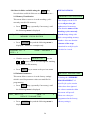
Physically check the stylus height above the
component and check that it is the same as the value
entered under DIST
in the “Stylus Parameter
Menus”, (i.e. 2.0mm). After any adjustment check
that the marking unit is firmly secured.
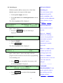
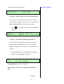
7.2 Dummy - Test Marking Run
A facility exists to check the stylus movements
programmed without marking the component.
•
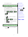
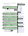
Press the
ESC
key to display the following
menu.
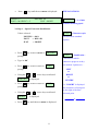
DOT_ DIST = 0.2
MEM NO. = 0
•
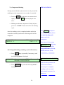
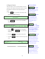
Press the
PWM = 15
TIME =
ALT
P
key once. This will turn off the air
supply to the stylus and the letter
P
shown on
the right hand side of the display will become, p
(lower case), confirming that the air is turned off.
•
Press the “START” button and the stylus will
proceed to simulate the marking cycle by following
the path programmed but without marking the
component.
23