1
LF
LL
LFÜ
Abw
ATM
KU
KV
LF
I1 I2
E10
Z1+
Z2-
W2
E2
W1
MODE
E-Nr.:21/0301(01)
ZW 05 D CU
E15
E5
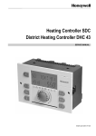
Central control unit
KV
ATW
E4
E1
KV
DC-Zentralsteuergerät
E3
L N LL LF LZ KU SH
LZ
LF
Dimplex
Charge
controller
N
Z
T
I
í
AR 05DCU
LG1
77%
SH SH SH SH
L N F 1 2 3 4
Peripheral zone
heating
Underfloor
storage heating
Residual heat sensor
Mod
SH 4
SH 3
SH 2
SH 1
KV Z1+ Z2- TF TF1 TF2 TF3 TF4
/I2 /I1
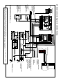
ZW 05 DCU connection diagram for underfloor heating
Inside
External sensor
Outside
Reduction contact
(optional) for characteristic
curve switching
to KU terminal
N
L1
Enabling signal
(LF or LZ)
tariff time switch or
ripple control receiver
Example
Enabling signal LF and
LZ separate
tariff time switch or
ripple control receiver
Example B
The SH characteristic “SHC” in the menu of
the ZW 05 DCU central control unit must be set to “LF”.
Heating
circuit
contactor1
í
KV
Z1+/I2
Z2-/I1
TF
TF1
TF2
TF3
TF4
L1
L2
L3
N
PE
L1
Central control unit
with control signal
-2,85 ... -3,6V
KV/KU
Z1
Z2
High tariff
power supply connection
Power supply connection
(heating circuit)
Switching off the heating element
that includes the residual
,
heat
sensor necessitates
switching off all heating
elements of the same heating
circuit
To electric
storage heaters
Transmission of control signal
of any electric
storage heaters
-2,85 ... -3,6V
Main
contactor
AR 05 DCU charge controller
To further
heating circuits
Room temp.
controller
with floor
temperature limiter
N
PE
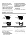
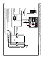
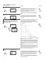
The ZW 05 DCU microprocessor-driven charge control has 2 separate control signal outputs.
The charge controllers for underfloor storage heating AR 05DCU or storage heaters can be connected to the Z1+, Z2- terminals (0.91 ... 1.43V). Charge controllers for underfloor
storage heaters with control signal -2.85 ... -3.6 V (e.g. Type AR 1741 ... AR 1744, RFV 351 DC ... RFV 354 DC) to terminals I1, I2 .
11