1
Unit Description
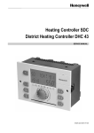
The ZW 05 DCU microprocessor-driven charge control
controls the charging of an underfloor storage heating
and/or the charging of storage heating devices
according to outside temperature, settings and control
signals.
It has the following features:
Charging according to external temperature,
Initial heating program for screed flooring,
Timer function for backward, intermediate and forward
control,
Priority and secondary use of actual service release
periods for low and high tariffs,
Adjustable detection of service release period (charge
release detection)
Direct control via charge control line Z1+/Z2- is possible,
Automatic correction of charging during extreme
temperature fluctuations (daytime and night-time
temperatures) in transition periods, via external
temperature averaging,
Characteristic curve switching via external control
is possible,
Large, back-lit, alphanumeric multi-function display
showing operating status and service information,
All utility company requirements can be met,
Optional connection to NTC or older PTC external
sensors,
Real-time timer to lower charging (weekly programme
and absence of up to 30 days).
Scope of delivery
- The ZW 05 DCU microprocessor-driven central control
unit
- NTC external sensor with 2 m connecting lead
- Installation and operating Instructions
Technical Information
ZW 05 DCU microprocessor-driven charge control
Connection voltage
Power consumption
Reference variable at the Z1+, Z2- terminals:
Reference variable at the I2, I1 terminals:
Number of charge controllers that can be activated
Power reserve
Switching capacity of safety output
Ambient temperature
Protection class
Degree of protection
Standard
Space requirements
Attachment
Connection terminals
Dimensions
Weight
1/N/ 230 V AC ~ 50/60 Hz
Approx. 2 VA
0.91 V to 1.43 V DC, safety overlap to 1.68 / 1.95 V
-2.85 V to -3.60 V DC, safety overlap to -4.35V
100 maximum
Approx. 6 hours (runtime and timer)
6A, 230 V ~
Between 0 °C and 50 °C
II according to installation (see section on “Installation”)
IP 20, according to DIN 40050, according to installation
DIN EN 50350 and DIN 44576 (draft)
6 x DIN 43880 modular spaces
Top hat rail
15, cross section 2.5 mm²
See dimension drawing
Approx. 320g
External sensor
Sensor type
Connecting pipe
Protection class
Degree of protection
Dimensions
See dimension drawing
NTC sensor according to DIN EN 50350 in insulated casing
2 m long (extendable up to a maximum of 30 m)
II according to DIN EN 60730-1
IP54 according to DIN 40050
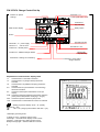
105
10
S
KV
I1
I2
1
2
3
D im p lex
50 mm
LL
AT M
LF
Abw
LZ
LF Ü
E5
AT W
E2
E4
KU
KV
E3
E 15
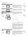
E 10
E1
230V
L
4
50 Hz
N
5
LL
LF
LZ
KU
6
7
8
9
83
ZW 05D CU
D C - Z e n t r a ls t e u e r g e r ä t
2 VA
12
MODE
E - N r. : 2 1 /0 3 0 1 ( 0 1 )
6A
SH
KV
Z1
Z2
W2
W1
10
11
12
13
14
15
3