1
Electrical connection
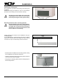
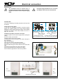
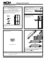
Connection, input E1 (24 V), zero volt
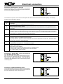
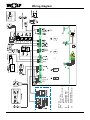
Connect the cable for input 1 at terminals E1 in accordance
with the wiring diagram; first remove the jumper between a
and b from the respective terminals.
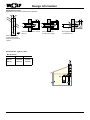
Figure: Connection, room thermostat
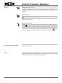
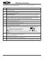
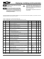
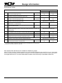
The functions of input E1 can be scanned and adjusted with Wolf control accessories with eBUS capability. The following
functions can be allocated to input E1:
Code
Explanation
0
No function
Input E1 is not taken into consideration by the control unit
1
Room thermostat (factory setting)
With open input E1, heating operation will be blocked (summer mode), independent of any digital Wolf control
accessories.
2
Maximum thermostat, system pressure switch or condensate lifting system
Connection option for a maximum thermostat, system pressure switch or condensate lifting system. To enable
the burner, input E1 must be closed. As long as the contact is open, the burner will remain blocked for DHW and
central heating, incl. emissions test mode and frost protection.
3
N/A
4
Flow limiter
Connection option for an additional water flow limiter.
After pump activation, input E1 must be closed within 12 seconds. Where this is not the case, the burner will be
switched OFF, and fault 41 will be displayed.
5
Monitoring the ventilation air damper
See parameters of output A1, no. 7. Ventilation air damper
8
Burner block (BOB)
Operation without burner
Closed contact, burner blocked
Heating circuit pump and cylinder primary pump run in standard mode
In emissions test mode and frost protection the burner is enabled
Open contact enables the burner again
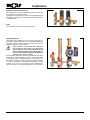
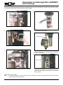
Connection, digital Wolf control accessories
(e.g. BM, MM, KM, SM1, SM2)
Only connect control units from the Wolf accessory range.
Each accessory is supplied with its own connection diagram.
Use a two-core cable (cross-section > 0.5 mm²) as the
connecting cable between the control unit accessory and the
condensing boiler.
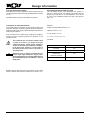
Figure: Digital Wolf control accessories connection (eBUS interface)
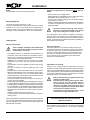
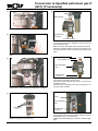
Connection, outside temperature sensor
The outside temperature sensor for digital control accessory
may be connected to the terminal strip of the boiler connection
AF, or the terminal strip of the control accessory.
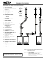
Figure: Connection, outside temperature sensor
3062555_201507
21