1
MicroVAX Troubleshooting
and Diagnostics
Order Number EK-019AE-SG-005
digital equipment corporation
maynard, massachusetts
July 1988
September 1988
October 1988
March 1989
May 1989
The information in this document is subject to change without notice and should not be
construed as a commitment by Digital Equipment Corporation.
Digital Equipment Corporation assumes no responsibility for any errors that may appear in
this document.
The software, if any, described in this document is furnished under a license and may be used
or copied only in accordance with the terms of such license. No responsibility is assumed
for the use or reliability of software or equipment that is not supplied by Digital Equipment
Corporation or its affiliated companies.
© Digital Equipment Corporation 1988, 1989. All rights reserved.
Printed in U.S.A.
The READER'S COMMENTS form on the last page of this document requests the user's
critical evaluation to assist in preparing future documentation.
The following are trademarks of Digital Equipment Corporation:
COMPACTape
DDCMP
DEC
DECmate
DECnet
DEC server
DECUS
DECwriter
DELNI
DELQA
DEQNA
DESTA
DIBOL
DSSI
MASSBUS
MicroVAX
PDP
P/OS
Professional
Q-bus
Rainbow
ReGIS
RQDX
RSTS
RSX
RT
ThinWrre
ULTRIX.
UNIBUS
VAX
VAXcluster
VAXELN
VAXlab
VMS
VT
Work Processor
maMaOIB
TU
ML-S1239
FCC NOTICE: The equipment described in this manual generates, uses, and may emit
radio frequency energy. The equipment has been type tested and found to comply with the
limits for a Class A computing device pursuant to Subpart J of Part 15 of FCC Rules, which
are designed to provide reasonable protection against such radio frequency interference when
operated in a commercial environment. Operation of this equipment in a resid.ential area
may cause interference, in which case the user at his own expense may be required to take
measures to correct the interference.
This document was prepared using VAX DOCUMENT, Version 1.1.
Contents
Preface
vii
Chapter 1 Troubleshooting During Power-On
1.1 Autobooting the MicroVAX System ................... .
Autobooting MicroVAX 3300/3400/3800/3900 Systems, and
1.1.1
MicroVAX 3500/3600 Systems with Version 4.1 ROM Code
(or greater) .................................... .
Autobooting MicroVAX 3500 and 3600 Systems ........ .
1.1.2
Autobooting MicroVAX II Systems .................. .
1.1.3
1.2 Troubleshooting Power-On Problems .................. .
1-1
1-1
1-1
1-2
1-2
Chapter 2 Troubleshooting During Normal Operation
Chapter 3
Running the MicroVAX Diagnostic' Monitor (MOM)
3.1
Running MDM Under Special Circumstances. . . . . . . . . . . .
3.1.1
Running MDM on Diskless and Tapeless Systems. . . . . . .
3.1.2
Running MDM on a VAXserver 3602 System. . . . . . . . . . .
3.1.3
Installing MDM on RF-series ISE or Hard Disk. . . . . . . .
3.1.4
Running MDM on a Dual-Host System .............. :
3.1.4.1
Running MDM on a Dual-Host System with One Tape
Drive ..................................... "
3.1.4.2
Running MDM on a Dual-Host System with Two Tape
Drives ......................................
3.2
Starting MDM ............................ ; . . . . . . .
3.2.1
RX50 Diskette Instructions. . . . . . . . . . . . . . . . . . . . . . . .
3.2.2
TK50ITK70 Instructions. . . . . . . . . . . . . . . . . . . . . . . . . . .
Booting MDM Manually. . . . . . . . . . . . . . . . . . . . . . . . .
3.2.2.1
3.2.2.2
Booting MDM Using Autoboot . . . . . . . . . . . . . . . . . . . .
3-2
3-2
3-3
3-3
3-3
3-4
3-5
3~5
3-6
3-7
3-7
3-8
iii
3.2.2.3
VAXserver 3602 Systems . . . . . . . . . . . . . . . . . . . . . . ..
3.2.2.4
MDM TK50ITK70 Introductory Screen .............
3.3 Main Menu Options ............................... ,
3.3.1
Test the System . . . . . . . . . . . . . . . . . . . . . . . . . . . . . . . ..
Display System Configuration and Devices ........... ,
3.3.2
Display the System Utilities Menu ..................
3.3.3
3.3.3.1
IOADDRES ..................................
3.3.3.2
Customer Disk Drive Formatter ..................
3.3.3.3
Update Drive Unit Number for RRD40 ............ ,
Display the Connect/lgnore Menu. . . . . . . . . . . . . . . . . ..
3.3.4
Select Single Device Tests .........................
3.3.5
Exiting MDM . . . . . . . . . . . . . . . . . . . . . . . . . . . . . . . . . ..
3.3.6
Appendix A
3-9
3-9
3-10
3-10
3-12
3-14
3-15
3-15
3-16
3-16
3-17
3-19
Diagrams for Locating Controls on Your MicroVAX
System
Index
Figures
3-1
3-2
3-3
3-4
3-5
3-6
3-7
A-I
A-2
A-3
A-4
A-5
A-6
A-7
A-8
iv
The Main Menu. . . . . . . . . . . . . . . . . . . . . . . . . . . . . . . . . ..
Example of an Unsuccessful Test ..................... ,
System Configuration and Devices Screen. . . . . . . . . . . . . ..
Sample System Utilities Menu. . . . . . . . . . . . . . . . . . . . . . ..
The Single Device Tests Menu . . . . . . . . . . . . . . . . . . . . . . ..
Example of a Successful Test ........................ ,
Example of an Unsuccessful Test ..................... .
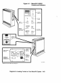
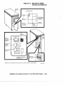
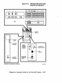
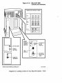
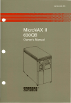
MicroVAX II 630QY Controls and Indicators ............ .
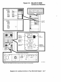
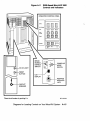
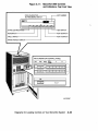
MicroVAX II 630QB Controls and Indicators ............ .
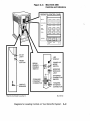
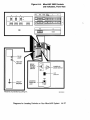
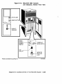
MicroVAX II 630QE Controls and Indicators ............ .
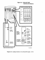
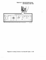
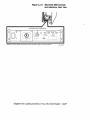
MicroVAX 3300 Controls and Indicators ............... .
MicroVAX 3400 Controls and Indicators ................
SDI-Based MicroVAX 3500 Controls and Indicators ........
DSSI-Based MicroVAX 3500 Controls and Indicators .......
MicroVAX 3600 Controls and Indicators, Front View. . . . . ..
3-10
3-11
3-12
3-15
3-17
3-18
3-18
A-3
A-5
A-7
A-9
A-11
A-13
A-15
A-17
A-9
A-10
A-ll
A-12
A-13
MicroVAX 3600
MicroVAX 3800
MicroVAX 3900
MicroVAX 3900
MicroVAX 3900
Controls
Controls
Controls
Controls
Controls
and Indicators,
and Indicators
and Indicators,
and Indicators,
and Indicators,
Rear View .......
................
Top Front View ...
Bottom Front View.
Rear View .......
A-19
A-21
A-23
A-25
A-27
Troubleshooting Power-On Problems. . . . . . . . . . . . . . . . . . .
Troubleshooting Operation Problems. . . . . . . . . . . . . . . . . ..
1-3
2-1
Tables
1-1
2-1
v
/
Preface
Troubleshooting is the process of isolating and diagnosing problems with
your system. When your system does not operate as described in Operation,
use the information in this guide to diagnose the problem.
This book contains troubleshooting information for all MicroVAXlVAXserver
systems: MicroVAX II and MicroVAX 3000-series systems. Appendix A
contains diagrams of each MicroVAX system. Using the diagram of your
system, follow the troubleshooting procedures recommended in this guide.
This manual contains three chapters:
•
Chapter 1 describes problems you may experience at power-on and
corrective actions.
•
Chapter 2 describes problems you may have during normal operation
of your system and corrective actions.
•
Chapter 3 describes the MicroVAX Diagnostic Monitor (MDM), a
diagnostic tool you can use to test your system periodically or to isolate
a particular problem.
•
Appendix A contains diagrams of each system showing the location of
the controls and indicators.
The troubleshooting techniques described in this manual do not identify all
possible problems with your system, nor do the actions suggested remedy
all problems. If the actions suggested do not solve the problem, call your
DIGITAL service representative.
vii
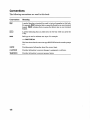
Conventions
The following conventions are used in this book:
Convention
Meaning
A symbol denoting a terminal key used in text and examples in this book.
For example, IBreak I indicates that you press the Break key on your terminal
keypad. IReturn I indicates that you press the Return key on your terminal
keypad.
A symbol indicating that you hold down the CtrI key while you press the
Ckey.
Bold
Bold type is used to indicate user input. For example:
»> BQOT MUAO
This line shows that the user must type BOOT MUAO at the console prompt
»>.
NOTE
Provides general information about the current topic.
CAUTION
Provides information to prevent damage to equipment or software.
WARNING
Provides information to prevent personal injury.
viii
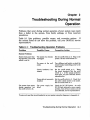
Chapter 1
Troubleshooting During Power-On
When you power on your system, the MicroVAX processor performs a series
of self-tests and start-up routines. After successful completion of the selftests, if the Break EnabieIDisable1 switch is set to disable, the system
attempts to autoboot system software.
1.1 Autobooting the MicroVAX System
The MicroVAX autoboot function is different for each MicroVAX system.
1.1.1 Autobooting MicroVAX 3300/3400/3800/3900 Systems,
and MicroVAX 3500/3600 Systems with Version 4.1
ROM Code (or greater)
The MicroVAX 3300,3400,3800,3900 systems, as well as those MicroVAX
3500 and 3600 systems using version 4.1 ROM code or greater, attempt to
automatically boot (autoboot) from a specified drive when you have used
the Set Boot command (SET BOOT device name) from console mode. The
system continues to boot from the specified device each time it is powered
on until you specify differently by using the Set Boot command again.
If you have not used the Set Boot command, the system boots automatically
from the Ethernet port, ESAO.
1.1.2 Autobooting MicroVAX 3500 and 3600 Systems
The MicroVAX 3500 and 3600 systems using version 1.2 or 1.4 ROM code,
attempt to autoboot a specific drive when you use the Set Boot command
(SET BOOT device name) from console mode. The system continues to
boot from the specified device each time it is powered on until you specify
differently by using the Set Boot command again.
If you have not used the Set Boot command, the system attempts to
autoboot by looking for bootable software the same way a MicroVAX II
system looks for bootable software. See Section 1.1.3 for more information.
1
MicroVAX II systems have a Halt EnablelDisable switch.
Troubleshooting During Power-On 1-1
1.1.3 Autobooting MicroVAX II Systems
When a MicroVAX II system attempts to autoboot, it looks for bootable
software on the following devices in the order shown below:
1. Removable disks and diskettes (RX33, RX50, and RA60 in ascending
unit number)
2. Fixed-disk drives (RD-serieslRA-seriesIRF-series in ascending unit
number)
3. Tape cartridges (TK50trK70, TS05, TU81-Plus)
4. EPROM
5. Ethernet adapter
Normally, the system automatically boots system software which has been
installed on a fixed-disk drive. When booting a fixed-disk drive, you must
remove all removable disks and place all disks ahead of the disk containing
the system software off-line. For example, if you want to boot system
software from an RA81 or RA82 fixed disk, place all removable media, as
well as all RD-series and RF-series disks, and RA60 disks (if any) off-line.
(See operating instructions for each drive in your system-specific Operation
manual.)
To boot software from a TK50 or TK70 tape cartridge, or the Ethernet, you
must place all removable and fixed-disk drives off-line.
An alternative to placing disks off-line is to boot your system manually
from the console terminal using the BOOT device name command in console
mode. (See Operation for more information.)
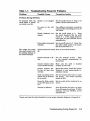
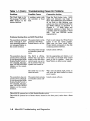
1.2 Troubleshooting Power-On Problems
If you do not observe the correct power-on and boot sequence responses,
refer to the possible problems and corrective actions described in Table 1-I.
If the actions listed do not solve the problem, call your DIGITAL service
representative.
NOTE: Table 1-1 occasionally recommends that you run MDM as a service
tool to help diagnose problems. Refer to Chapter 3 of this manual for
instructions on using MDM.
1-2 MicroVAX Troubleshooting and Diagnostics
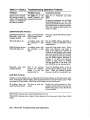
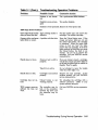
Table 1-1: Troubleshooting Power-On Problems
(
\
Problem
Possible Cause
Corrective Action
Problems During Self-Thsts
No response when the
on/off switch is turned
on (switch is not lit).
System is not plugged
in.
Set the on/off switch to O. Plug in the
system. Set the on/off switch to 1.
No power at the wall
outlet.
Use a different wall outlet, or check the
circuit breaker controlling power to the
wall outlet.
Circuit breaker(s) has
tripped.
Set the on/off switch to O. Reset
the circuit breaker(s).lSet the on/off
switch to 1. If the circuit breaker(s)
trips again, call your DIGITAL service
representative.
Power cable is incorrectly Set the on/off switch to O. Check that
installed.
the cable is fully seated in the socket.
Set the on/off switch to 1.
The system has power
(the on/off switch is lit),
but nothing displays on
the console terminal.
1 Locate
Console terminal is turned Tum on the console terminal.
off.
Console terminal is offline.
Put the terminal on-line.
Refer
to the terminal documentation for
instructions.
Console terminal cable
is not installed correctly.
Make sure the cable is installed
properly at both ends.
Console terminal SetUp has not been done
correctly.
Reread the section, Install the Console
Terminal, in your system-specific Installation manual.
Baud rate setting of the
system and the terminal
do not match.
Set the terminal baud rate to match
the system. The normal operating
setting is 9600.
Power-Up Mode switch
on the CPU panel is set
to T.
Set the switch to Run (indicated by an
Terminal is defective.
Tum off terminal and turn it on again
to see if it passes its self-tests. If it fails
self-tests, call your DIGITAL service
representative.
arrow).
and reset the circuit breaker(s) on your system using the diagrams in Appendix A.
Troubleshooting During Power-On
1-3
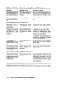
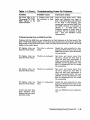
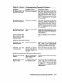
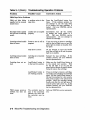
Table 1-1 (Cont.): Troubleshooting Power-On Problems
Problem
Possible Cause
Corrective Action
The self-tests halted and
an error message or error summary displays on
the console terminal.
The system detected an
error while running its
self-tests.
Copy the number following the question mark in the error message or summary and call your DIGITAL service
representative.
The system loses power,
but the on/off switch is
lit.
Power supply failure.
Call your DIGITAL service representative.
General Problems During Boot Sequence
The system returns to
the BOOT prompt after
four minutes.
Sanity timer is enabled
on the DELQA module.
Disable sanity timer. Refer to DELQASA Option Installation Guide.
Instead of automatically
starting, system poweron results in >>> being
displayed on the console
terminal.
Break EnabielDisable2
switch is set to enable.
The system is in console
mode.
To autoboot, set the Break Enable!
Disable2switch (located on the CPU
panel) to the disable position. Reset
the system by pressing the Reset3button,
located on the power supply.
If you prefer to boot manually from
console mode, use the BOOT command
(>>>BOOT device-name).
The message "?54
RETRY" displays on the
console terminal twice.
No bootable media was
found.
See actions listed in the subsequent
sections of this table for the boot device
you are using.
The countdown does not
continue from 2 through
0, even though the Break
EnabielDisable 2 switch is
set to disable.
The system cannot load
system software from
either a disk drive or a
tape drive.
See actions listed in the subsequent
sections of this table for the boot device
you are using.
Problems Booting from an RD-Series Fixed Disk
The countdown continues The system disk is writefrom 2 to 0; however, op- protected.
erating system error messages display on the console terminal.
Release the write-protection on the disk.
Make sure you know which Write-Protect
button/switch corresponds to the disk
containing system software. Refer to
your system-specific Operation manual
for instructions on operating your RDseries fixed disk.
2MicroVAX II systems have a Halt EnablelDisable switch.
3MicroVAX II systems have a Restart button located on the front panel, rather than a Reset
button.
1-4
MicroVAX Troubleshooting and Diagnostics
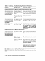
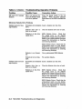
Table 1-1 (Cont.): Troubleshooting Power-On Problems
Problem
Possible Cause
Corrective Action
The countdown does not The system disk is offcontinue from 2 through line.
0, even though the Halt
EnablelDisable switch is
set to disable. The message "?4D DEVOFFLINE"
displays on the console
terminal.
Set the Ready button to the out·
position (glows green).
The countdown does not The system disk contains
continue from 2 through no bootable system soft0, even though the Halt ware.
EnablelDisable switch is
set to disable. The mes~
sage "?42 NOSUCHFILE"
displays on the console
terminal.
Install system software.
The countdown does not
continue from 2 through
0, even though the Halt
EnableIDisable switch is
set to disable. The message "?4C CTRL ERR"
displays on the console
terminal.
Run the MDM software as described in
Chapter 3.
A problem exists with
the controller or fixed
disk.
Problems Booting from an RA60 Removable Disk Drive
The countdown does not
continue from 2 through
0, even though the Break
EnabieIDisable2switch is
set to disable. The system cannot load system
software from the RA60
disk.
The system disk is writeprotected. The WriteProtect button is in (lit).
Push in and release the Write-Protect
button to the out position. Make sure
you know which Write-Protect button
corresponds to the disk containing
system software.
The disk is not spun-up.
The Run/Stop button on
the disk drive control
panel was not set to the
in position.
Set the Run/Stop button on the disk
drive control panel to the in position.
Open the front door of the cabinet and
press the Reset3button on either power
supply.
The RA60 drive door is
unlocked.
Close the RA60 drive door and make
sure the lock release button is out.
2MicroVAX II systems have a Halt EnablelDisable switch.
3MicroVAX II systems have a Restart button located on the front panel, rather than a Reset
button.
Troubleshooting During Power-On
1-5
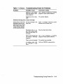
Table 1-1 (Cont.): Troubleshooting Power-On Problems
Problem
The countdown does not
continue from 2 through
0, even though the Break
EnabielDisable2switch is
set to disable. The message "?4D DEVOFFLINE"
displays on the console
terminal.
Possible Cause
Corrective Action
The disk drive circuit
breaker is tripped.
Press the RunlStop button on the disk
drive control panel to the out position.
Reset the circuit breaker on the disk
drive by pushing it down, then up
again. Press the RunlStop button to
the in position. Press the Reset3button
on either power supply.
A problem exists with
the controller or fixed
disk.
Run the MDM software as described in
Chapter 3.
The RA60 is off-line.
Neither the A nor the B
button on the disk drive
control panel was set to
the in position when the
system was turned on.
Set the appropriate port button, A or
B (or both), on the disk drive control
panel to the in position. Press the
Reset3button on either power supply.
The countdown does not The system disk contains
continue from 2 through no bootable system soft0, even though the Break ware.
EnabielDisable2switch is
set to disable. The message "142 NOSUCHFILE"
displays on the console
terminal.
Install system software.
The Fault light is lit.
The message ''?4C CTRL
ERR" displays on the
console terminal.
Press the Fault button twice. RA60
lights and indicators may begin to
flash. If the RA60 lights and indicators
do not flash or stop flashing, your
system may. have corrected itself; Run
the MDM software as described in
Chapter 3.
If RA60 lights and
indicators continue to flash, there is
a problem with the controller or fixed
disk.
Call your DIGITAL service
representative.
A problem exists with
the controller or fixed
disk.
2MicroVAX II systems have a Halt EnablelDisable switch.
3MicroVAX II systems have a Restart button located on the front panel, rather than a Reset
button.
1-6 MicroVAX Troubleshooting and Diagnostics
Table 1-1 (Cont.): Troubleshooting Power-On Problems
Problem
Possible Cause
Corrective Action
Problems Booting from an RASO-Series Fixed Disk
The countdown does not The system disk is writecontinue from 2 through protected. The Write0, even though the Break Protect button is in (lit).
EnableIDisable2 switch is
set to disable. The system cannot load system
software from a fixed disk.
Push in and .release the Write-Protect
button to the out (unlit) position.
Make sure you know which WriteProtect button corresponds to the disk
containing system software.
The disk is not spun-up.
The Run/Stop button on
the disk drive control
panel was not set to the
in position.
Set the Run/Stop button on the disk
drive control panel to the in position.
Open the front door of the cabinet and
press the Reset3button on either power
supply.
The disk drive circuit
breaker is tripped.
Press the Run/Stop button on the disk
drive control panel to the out position.
Reset the circuit breaker on the disk
drive by pushing it down, then up
again. Press the Run/Stop button to
the in position. Press the Reset3button
on either power supply.
A problem exists with
the controller or fixed
disk.
Run the MDM software described in
Chapter 3.
The RA80 is off-line.
Neither the A nor the B
button on the disk drive
control panel was set to
the in position when the
system was turned on.
Set the appropriate port button, A or
B (or both), on the disk drive control
panel to the in position. Press the
Reset3button on either power supply.
The countdown does not
continue from 2 through
0, even though the Break
EnableIDisable2 switch is
set to disable. The message "?4D DEVOFFLINE"
displays on the console
terminal.
The countdown does not The system disk contains
continue from 2 through no bootable system soft0, even though the Break ware.
EnableIDisable 2 switch is
set to disable. The message "?42 NOSUCHFILE"
displays on the console
terminal.
Install system software.
2MicroVAX II systems have a Halt Enable!Disable switch.
3MicroVAX II systems have a Restart button located on the front panel, rather than a Reset
button.
Troubleshooting During Power-On
1-7
Table 1-1 (Cont.): Troubleshooting Power-On Problems
Problem
Possible Cause
Corrective Action
The Fault light is lit.
The message "?4C CTRL
ERR" displays on the
console terminal.
A problem exists with
the controller or fixed
disk.
Press the Fault button twice. RA80
lights and indicators may begin to
flash. If the RA80 lights and indicators
do not flash or stop flashing, your
system may have corrected itself. Run
the MDM software as described in
Chapter 3.
If RA80 lights and
,indicators continue to flash, there is
a problem with the controller or fixed
disk.
Call your DIGITAL service
representative.
Problems Booting from an RA70 Fixed Disk
The countdown continues The system disk is writefrom 2 through 0, how- protected. The Writeever, operating system er- Protect button is in (lit).
ror messages display on
the console terminal.
The countdown does not
continue from 2 through
0, even though the Break
EnabielDisable2switch is
set to disable. The message ''?4D DEVOFFLINE"
displays on the console
terminal.
Push in and release the Write-Protect
button to the out (unlit) position.
Make sure you know which WriteProtect button corresponds to the disk
containing system software.
The system disk contains
no bootable system software.
Install system software.
The RA70 is off-line.
Neither the A nor the B
button on the disk drive
control panel was set to
the in position when the
system was turned on.
Set the appropriate port button, A or
B (or both), on the disk drive control
panel to the in position. Press the
Reset3button on either power supply.
The RA70 has not finished self-tests.
Wait until the Ready light comes on
and press the Reset button3 0n either
power supply.
The countdown does not The system disk contains
continue from 2 through no bootable system soft0, even though the Break ware.
EnabielDisable2switch is
set to disable. The message ''?42 NOSUCHFILE"
displays on the console
terminal.
Install system software.
2MicroVAX II systems have a Halt EnablelDisable switch.
3MicroVAX II systems have a Restart button located on the front panel, rather than a Reset
button.
1-8 MicroVAX Troubleshooting and Diagnostics
Table 1-1 (Cont.): Troubleshooting Power-On Problems
Problem
Possible Cause
Corrective Action
The Fault light is lit.
The message "?4C CTRL
ERR" displays on the
console terminal.
A problem exists with
the controller or fixed
disk.
Press the Fault button twice. RA70
lights and indicators may begin to
flash. If the RA70 lights and indicators
do not flash or stop flashing, your
system may have corrected itself. Run
the MDM software as described in
Chapter 3.
If RA70 lights and
indicators continue to flash, there is
a problem with the controller or fixed
disk.
Call your DIGITAL service
representative.
Problems Booting from an RA90 Fixed Disk
Problems with the RA90 drive are indicated by the Fault indicator on the front panel of the
drive. If the Fault indicator lights, or if no front panel activity occurs at power-up, select the
Fault switch on the drive's front panel. When you select the Fault switch, a fault code should
display on the control panel.
. OF displays when you
select the Fault switch.
The drive is write protected.
Disable the write protection by deselecting the Write-Protect switch at the
RA90 control panel or turn off software
write protection.
22 displays when you
select the Fault switch.
The drive is overheated.
Spin down and remove power from
the drive. Ensure the front filter is
clean and that room temperature is
within recommended limits. Call your
DIGITAL service representative if the
filter or temperature has not caused
the overheating.
2D displays when you
select the Fault switch.
The drive is overheated.
Spin down and remove power from
the drive. Ensure the front filter is
clean and that room temperature is
within recommended limits. Call your
DIGITAL service representative if the
filter or temperature has not caused
the overheating.
6F displays when you
select the Fault switch.
There is a write-protect
error.
Disable the write protection by deselecting the Write-Protect switch at the
RA90 control panel or turn off software
write protection.
A fault code other than
those described above
displays when you select
the Fault switch.
Call your DIGITAL service representative.
Troubleshooting During Power-On
1-9
Table 1-1 (Cont.): Troubleshooting Power-On Problems
Problem
Possible Cause
Corrective Action
Problems Booting from an RF-Series Integrated Storage Element (lSE)
The countdown continues
from 2 through 0, however, operating system error messages display on
the console terminal.
The system disk is writeprotected. The WriteProtect button is in (glows
orange).
Push in and release the Write-Protect
button to the out (unlit) position. Make
sure you know which Write-Protect
button corresponds to the system disk.
The system disk contains
no bootable system software.
Install system software.
The countdown does not
continue from 2 through
0, even though the Break
EnabielDisable2switch is
set to disable.
The system disk is offline. (The Ready button
is in the in position.)
Press the appropriate Ready button, 0,
I, or 2, to the out position. Press the
Reset3button on either power supply.
The Fault light is lit or
begins to flash.
A problem exists with
the controller or ISE.
If the Fault light stops flashing, your
system may have corrected itself.
Run the MDM software as described
in Chapter 3. If the Fault light
remains lit, call your DIGITAL service
representative.
Problems Booting from an RX-Series Diskette Drive
System does not boot (the No diskette in diskette· Insert a diskette containing startable
countdown does not con- drive.
system software into the diskette
tinue from 2 to 0) or boots
drive.
from another device (the
wrong software displays
on the console terminal).
Diskette drive door or
latch is not closed.
Close the diskette drive door or latch.
Diskette is in the drive
upside down.
RX50 Diskette Drives: Check that the
orange arrow on the diskette matches
the orange stripe on the drive. Refer to
Operation for instructions on inserting
and removing diskettes.
RX33 Diskette Drives: Check that the
write-protect notch is at the bottom.
Refer to Operation for instructions on
inserting and removing diskettes.
2MicroVAX II systems have a Halt EnablelDisable switch.
3MicroVAX II systems have a Restart button located on the front panel, rather than a Reset
button.
1-10 MicroVAX Troubleshooting and Diagnostics
Table 1-1 (Cont.): Troubleshooting Power-On Problems
Problem
Possible Cause
Corrective Action
Diskette is not bootable
(does not contain a bootstrap program).
Use a diskette containing a bootstrap
program to start system software.
Diskette is worn or damaged.
Try another diskette.
Problems Booting from a Tape Cartridge
System does not boot (the No tape cartridge in the
countdown does not con- tape drive.
tinue from 2 to 0) or boots
from another device (the
wrong software displays
on the console terminal).
Fixed-disk drive is online. Your system starts
from the fixed disk, if it
is on-line.
Insert a cartridge containing system
software into the tape drive.
Place the fixed disk off-line.
Tape is not bootable (does Use a tape containing a bootstrap
not contain a bootstrap program to start system software.
program).
Tape is worn or damaged.
Try another tape cartridge.
A problem exists with
the controller or tape
drive.
Call your DIGITAL representative.
Troubleshooting During Power-On
1-11
Chapter 2
Troubleshooting During Normal
Operation
Problems that occur during normal operation of your system may result
from a defect in the system, from faulty settings, or from incorrect
procedures.
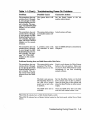
Table 2-1 lists problems, possible causes, and corrective actions. If
the actions listed do not solve the problem, call your DIGITAL service
representative.
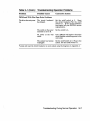
Table 2-1: Troubleshooting Operation Problems
Problem
Possible Cause
Corrective Action
The system has become
unplugged.
Set the on/off switch to o. Plug in the
system. Set the on/off switch to 1.
No power at the wall
outlet.
Use a different wall outlet, or check the
circuit breaker controlling power to the
wall outlet.
Circuit breaker(s) has
tripped.
Set the on/off switch to O. Reset
the circuit breaker(s).lSet the on/off
switch to 1. If the circuit breaker(s)
trips again, call your DIGITAL service
representative.
System Problems
System loses power during operation. The on/off
switch is not lit.
Power cable is incorrectly Set the on/off switch to o. Check that
installed.
the cable is fully seated in the socket.
Set the on/off switch to 1.
The system loses power
during operation, but
the on/off switch is lit.
1 Locate
The power supply has
failed.
Check the DC OK light(s). An unlit
DC OK light indicates a power supply
problem. 'fum off your system and call
your DIGITAL service representative.
and reset the circuit breaker(s) on your system using the diagrams in Appendix A.
Troubleshooting During Normal Operation
2-1
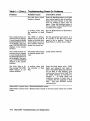
Table 2-1 (Cont.): Troubleshooting Operation Problems
Problem
Possible Cause
The IBreakl key on the
System halts unexpectedly during normal op- console terminal vvas
eration. The console mode pressed inadvertently.
prompt> >> displays on
the console terminal.
Corrective Action
Type "C" or "Continue" and press
IRetumL
1b prevent recurrences, set the Break
EnabielDisable2svvitch on the CPU
panel to the disable position and press
the Reset3button to reset the system.
Note that pressing Reset3causes the
system to reboot.
RA60170/81182 Disk Problems
RA70 Fixed-Disk Drives:
Fixed-disk "Write error
message displays.
Disk is "Write-protected.
(Write-Protect button
glovvs orange).
Press and release Write-Protect button
(not lit).
The Fault light is lit.
A problem exists vvith
the controller or disk
drive.
Run the MDM softvvare described in
Chapter 3. Call your DIGITAL service
representative.
RA60 / 80-Series Devices:
The Fault light is lit.
A problem exists vvith
the controller or disk
drive.
Press the Fault button tvvice. Device
lights and indicators may begin to
flash. If the lights and indicators do
not flash or stop flashing, your system
may have corrected itself. 1b be certain
that your system is operating correctly,
run the MDM softvvare described in
Chapter 3. If lights and indicators
continue to flash, there is a problem
vvith the controller or disk drive. Call
your DIGITAL service representative.
Fixed-disk read error
message displays.
Disk is not spun-up
because the RunlStop
button is in the out
position (not lit).
Press the Run/Stop button to the in
position (glovvs yellovv) to spin up the
drive. When the ~ADY indicator
comes on, the drive is available for use.
RADO Disk Problems
Problems vvith the RA90 drive are indicated by the Fault indicator on the front panel of the
drive. If the Fault indicator lights, select the Fault svvitch on the drive's front panel. When
you select the Fault svvitch, a fault code should display on the control panel.
OF displays vvhen you
select the Fault svvitch.
The drive is vvrite protected.
Disable the "Write protection by deselecting the Write-Protect svvitch at the
RA90 control panel or turn off softvvare
"Write protection.
2MicroVAX II systems have a Halt EnablelDisable svvitch.
3MicroVAX II systems have a Restart button located on the front panel, rather than a Reset
button.
2-2
MicroVAX Troubleshooting and Diagnostics
(
Table 2-1 (Cont.): Troubleshooting Operation Problems
Problem
Possible Cause
Corrective Action
22 displays when you
select the Fault switch.
The drive is overheated.
Spin down and remove power from
the drive. Ensure the front filter is
clean and that room temperature is
within recommended limits. Call your
DIGITAL service representative if the
filter or temperature has not caused
the overheating.
2D displays when you
select the Fault switch.
The drive is overheated.
Spin down and remove power from
the drive. Ensure the front filter is
clean and that room temperature is
within recommended limits. Call your
DIGITAL service representative if the
filter or temperature has not caused
the overheating.
6F displays when you
select the Fault switch.
There is a write-protect
error.
Disable the write protection by deselecting the Write-Protect switch at the
RA90 control panel or turn off software
write protection.
A fault code other than
those described above
displays when you select
the Fault switch.
Call your DIGITAL service representative.
RD-Series Fixed-Disk Problems
Fixed-disk write error
message displays.
Disk is write-protected.
Release the write protection for the
disk. Refer to your system-specific
Operation manual for instructions on
operating your RD-series fixed disks.
Fixed-disk read error
message displays.
MicroVAX II Systems:
Disk is off-line because
the Ready button is in
(not lit).
Press and release the Ready button
(glows green) to put fixed disk on-line.
RF-Series Integrated Storage Element (lSE) Problems
ISE write error message
displays.
ISE is write-protected.
(Write-Protect button
glows orange).
Press and release Write-Protect button
(not lit).
The Fault light is lit or
A problem exists with
begins to flash.
the controller or ISE.
If the Fault light stops flashing, the
system may have corrected itself.
Run the MDM software as described
If the Fault light
in Chapter 3.
remains lit, call your DIGITAL service
representative.
Troubleshooting During Normal Operation 2-3
Table 2-1 (Cont.): Troubleshooting Operation Problems
Problem
Possible Cause
Corrective Action
ISE read error message
displays.
ISE is not spun-up because the Ready button
is in the in position.
Press the Ready button to the out
position. When the green indicator
light comes on, the ISE is available for
use.
RX-Series Diskette Drive Problems
Diskette read error message displays.
No diskette in the diskette Insert a diskette into the drive.
drive.
Diskette drive door or
latch is not closed.
Close the diskette drive door or latch.
Diskette is in the drive
upside down.
RX50 Diskette Drives: Check that
the orange arrow on the diskette
matches the orange stripe on the drive.
Refer to your system-specific Operation
manual for instructions on inserting
and removing diskettes.
RX33 Diskette Drives: Check that the
write-protect notch is at the bottom.
Refer to your system-specific Operation
manual for instructions on inserting
and removing diskettes.
Diskette write error message displays.
Diskette is not formatted.
Use a preformatted RX50 diskette.
Diskette is worn or damaged.
Try another diskette.
No diskette in the diskette Insert a diskette into the drive.
drive.
Diskette drive door or
latch is not closed.
Close the diskette drive door or latch.
Diskette is in the drive
upside down.
RX50 Diskette Drives: Check that
the orange arrow on the diskette
matches the orange stripe on the drive.
Refer to your system-specific Operation
manual for instructions on inserting
and removing diskettes.
RX33 Diskette Drives: Check that the
write-protect notch is at the bottom.
Refer to your system-specific Operation
manual for instructions on inserting
and removing diskettes.
2-4
MicroVAX Troubleshooting and Diagnostics
(
Table 2-1 (Cont.): Troubleshooting Operation Problems
Problem
Possible Cause
Corrective Action
Diskette is not formatted.
Use a preformatted RX50 diskette.
Diskette is worn or damaged.
Try another diskette.
Diskette is write-protected. Remove the write-protect tab.
TK70 Tape Drive Problems
Green light blinks rapidly Tape cartridge leader is
after you insert the tape. defective.
Pull the handle open and remove the
cartridge. Use another cartridge.
Orange, yellow, and green A problem with the drive. Press the Unload button once. If the
lights blink in unison.
orange and green lights go out and
the yellow light blinks, the cartridge
is unloading. When the green light
comes on and you hear the beep,
remove the tape cartridge. If all three
lights continue to blink after you press
the Unload button, the fault is not
cleared. Do not try to remove the
cartridge. Call your DIGITAL service
representative.
Power-on test is still in
progress.
If you are trying to insert a cartridge,
wait for the orange and yellow lights to
go off and the green light to remain on
steadily. Then try again.
Tape drive is active.
Do not attempt to move the handle
while the yellow light is on.
Handle does not lock.
Cartridge is not inserted
properly.
Reinsert the tape cartridge. If the
problem persists, call your DIGITAL
service representative.
Cartridge does not unload.
Unload button is not
working properly.
Try unloading the cartridge with a
software command. Refer to your
system software manuals.
TK70 passes power-on
self·test but does not
work.
The controller may be
bad, or the connection
between the drive and
the controller may be
loose.
Call your DIGITAL service representative.
Handle does not move.
Troubleshooting During Normal Operation
2-5
Table 2-1 (Cont.): Troubleshooting Operation Problems
Problem
Possible Cause
Corrective Action
TK50 Tape Drive Problems
TK50 red light blinks
rapidly, but no unusual
sounds occur.
A problem exists in the
tape drive.
Press the LoadlUnload button four
times. If the problem persists, do
not attempt to use the tape drive
or to remove the tape cartridge, if
loaded. Call your DIGITAL service
representative.
Red light blinks rapidly
and you hear a whirring
sound.
Leaders are not coupled
properly.
Immediately turn off the system
by setting the on/off switch to 0
(oft).
Call your DIGITAL service
representative. Do not attempt to
remove the cartridge.
Cartridge release handle
does not move.
Power-on test is still in
progress.
If you are trying to insert a cartridge,
wait for the red light to go out and the
green light to remain on steadily, then
try again.
Tape drive is active.
Do not attempt to move the handle
until the red light is off and the green
light is on steadily.
Cartridge release handle
does not lock.
Cartridge is not inserted
properly.
Reinsert the tape cartridge. If the
problem persists, call your DIGITAL
service representative.
Cartridge does not unload.
LoadlUnload button is
in the load (in) position.
Make sure the LoadlUnload button is
in the unload (out) position. Wait
for the red light to go out and the
green light to remain on steadily before
trying to remove the cartridge.
LoadlUnload button is
not working properly.
If you are trying to remove a cartridge,
try loading and unloading the cartridge
again. Set the LoadlUnload button to
the load (in) position for a few seconds,
then press it again to the unload (out)
position. Move the cartridge release
handle only after the red light goes off
and the green light comes on. If the
problem persists, call your DIGITAL
service representative.
The controller may be
bad, or the connection
between the drive and
the controller may be
loose.
Call your DIGITAL service representative.
TK50 passes power-on
self-test but does not
work.
2-6 MicroVAX Troubleshooting and Diagnostics
Table 2-1 (Cont.): Troubleshooting Operation Problems
Problem
Possible Cause
Corrective Action
TSV05 and TU81-Plus Tape Drive Problems
The drive does not power
up.
The circuit breaker(s)
has tripped.
Set the on/off switch to o. Reset
the circuit breaker(s).lSet the on/off
switch to l. If the circuit breaker(s)
trips again, call your DIGITAL service
representative.
The switch on the power
controller is set to B.
Set the switch to A.
No power at the wall
outlet.
Use a different wall outlet or check the
circuit breaker controlling power to the
wall outlet.
The system has become
unplugged.
Set the on/off switch to o. Plug in the
system. Set the on/off switch to l.
lLocate and reset the circuit breaker(s) on your system using the diagrams in Appendix A.
Troubleshooting During Normal Operation 2-7
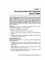
Chapter 3
Running the MicroVAX Diagnostic
Monitor (MOM)
The MicroVAX Diagnostic Monitor (MDM) is a software package containing
diagnostic tests designed to isolate and identifY faults in your MicroVAX
system. MDM also permits you to display your system configuration,
reformat disks, and, if your system has two or more megabytes of memory,
test how devices work together. The diagnostic tests are packaged with your
system on either RX50 diskettes (labeled MV DIAG CUST RX50) or a tape
cartridge (labeled MV DIAG CUST TK50). MDM operating instructions
begin in Section 3.2.
CAUTION: If your system is connected to a cluster, notify your cluster
manager before halting the system to load MDM.
You generally run MDM in three situations:
•
Before you install system software on a new system
•
When you receive an error message or experience a problem with your
system
•
When you want to test your system periodically to ensure that all
components are operating correctly
How the MOM Tests Work
MDM tests individual devices in your system. However, MDM performs
limited diagnostics:
•
It performs reads from each drive and checks each controller. The
customer tests do not write to the drives as writing to the drives could
destroy data.
NOTE: MDM will test a tape drive or diskette drive only when the media
(tape or diskette) is inserted in the drive.
•
It checks only devices themselves and not the connections or lines
between peripheral devices and the system.
Running the MicroVAX Diagnostic Monitor (MOM)
3-1
•
It does not check each device as thoroughly as the service diagnostic
tests, which are described below.
If devices pass the customer tests but you still experience problems, contact
a DIGITAL service representative for further testing.
Customers requiring more complete diagnostic testing should purchase the
MicroVAX Maintenance Kit. The maintenance kit includes the system
maintenance guide and the service diagnostic tests. The MDM version
that you receive with your system is a subset of the service version.
NOTE: Only qualified service personnel should use the service diagnostic
tests.
3.1 Running MOM Under Special Circumstances
Running MDM for certain systems requires additional or special
procedures. Read the appropriate section if you plan to run MDM on a
diskless and tapeless system, a VAXserver 3602 system, a dual-host system,
or if you plan to install MDM on a hard disk or RF-series Integrated Storage
Element (lSE).
3.1.1 Running MDM on Diskless and Tapeless Systems
If you have a diskless and tapeless system that is part of a local area
network (LAN), you must obtain the MicroVAX Ethernet Server Customer
Diagnostics Kit. Run MDM using the diagnostics in the kit that is labeled
MV DIAG ENET CUST.
Refer to the MicroVAX Diagnostic Monitor Ethernet Server User's Guide at
this time. Once you have installed and down-line loaded MDM software,
refer again to this manual for specific instructions on running MDM.
NOTE:
1. If you have a diskless and tapeless system that is not part of a local
area network (LAN), you cannot run MDM. To diagnose problems, call
a DIGITAL service representative.
2. If your system is part of a local area network (LAN), you may want to
reduce the time required to load MDM on each system by obtaining the
Micro VAX Ethernet Server Customer Diagnostics Kit. The kit enables
you to install MDM software on a host VMS operating system and downline load MDM to other systems that are part of the LAN, using the
DECnet / Ethernet network facilities. When MDM is down-line loaded
3-2 MicroVAX Troubleshooting and Diagnostics
to target systems from a host system, the time required to load MDM is
reduced significantly.
3.1.2 Running MDM on a VAXserver 3602 System
If you have a VAXserver 3602 system, the CPU in the secondary cabinet
cannot boot diagnostic software from a tape cartridge. You must down-line
load the diagnostic software from the primary cabinet.
The MicroVAX Ethernet Server Customer Diagnostics Kit contains the
MDM diagnostic software and a MicroVAX Diagnostic Monitor Ethernet
Server User's Guide. The user's guide describes how to install MDM
software on a host VMS or MicroVMS operating system and how to downline load MDM to a diskless target system, using the DECnet/Ethernet
network facilities.
3.1.3 Installing MDM on RF-series ISE or Hard Disk
MDM software can be installed on an RF-series ISE or an RA-, RDseries hard-disk drive using the MDM Hard Disk Kit. Installation of
the MDM Hard Disk Kit requires the completion of the "Diagnostic
Software Installation Acknowledgment" by the customer. See the Micro VAX
Diagnostic Monitor Hard Disk User's Guide for the licensing requirements
and installation instructions.
NOTE: The MDM Hard Disk Kit is required for dual-host systems where
one host is a tapeless system.
3.1.4 Running MDM on a Dual-Host System
In a dual-host configuration, two MicroVAX systems in the same VAXcluster
share their ISEs through a Digital Storage System Interconnect (DSSI) bus.
Each system can directly access any of the ISEs in either system; this can
include a shared common system disk.
Before running MDM diagnostics on a dual-host system, your system must
be properly configured (systems ordered as dual-host systems are properly
configured at the factory) and the DSSI cable connecting the two hosts must
be in place.
Diagnostics must be performed separately for each host. The procedure for
running diagnostics differs depending on whether one host is a tapeless
system (no tape drive) or each host has its own tape drive. Use the
instructions in Section 3.1.4.1 to run diagnostics in a dual-host system with
one tape drive. Use the instructions in Section 3.1.4.2 to run diagnostics in
dual-host systems with a tape drive in each host.
Running the MicroVAX Diagnostic Monitor (MDM)
3-3
3.1.4.1 Running MDM on a Dual-Host System with One Tape Drive
Dual-host systems with one tape drive (one tapeless host) require the
MDM Hard Disk Kit. Complete the "Diagnostic Software Installation
Acknowledgment" and install the kit on an RF-series ISE according to the
procedure in the Micro VAX Diagnostic Monitor Hard Disk User's Guide.
NOTE: Micro VAX II systems have a Restart button on the front panel, rather
than a Reset button; and a Halt Enable / Disable switch, rather than a Break
Enable / Disable switch. The text refers to the switches as the Reset switch
and the Break Enable / Disable switch.
When the installation is complete, use the following procedure to run the
diagnostics:
1. Set the Break EnablelDisable switch on both hosts' CPU panels to
enable (up, dot inside the circle). Turn on both hosts. If the hosts
are already powered-up, press IBREAKI.
Result: You should see the »> prompt indicating console mode on your
terminal.
2. Use the command BOOT/100 DIAn (for KA640 CPU based DSSI) or
BOOT/100DUAn (for KFQSA based DSSI), where n is the unit number
of the disk containing the MDM Hard Disk Kit.
Result: The system prompts for the boot:file:
Bootfile:
Enter the name of the :file image: [SYSO.SYSEXE]MDMDIA.SYS for
systems with on-board DSSI, or [SYSO.SYSEXE]MDM.SYS for systems
using the KFQSA storage adapter. Press IRETURN I to continue booting.
3. Run the diagnostics as described in this chapter.
4. When you have completed the tests on the first host, make sure the
Break EnablelDisable switch is set to enable (up, dot inside the circle)
and press the Reset button on that same host. When the countdown
completes and the »> prompt appears, boot the diagnostics from the
second host using the commands described in steps 2 and 3, and run
the diagnostics as you did for the first host.
3-4 MicroVAX Troubleshooting and Diagnostics
3.1.4.2 Running MDM on a Dual-Host System with Two Tape Drives
Run diagnostics on dual-host systems with two tape drives according to the
following procedure:
NOTE: You can also use the MDM Hard Disk Kit as described in the
previous section.
1. If software is installed on the system, warn all users to log off
and perform system shutdown, as described in your system software
manuals. Turn off both hosts.
2. Make sure the Write-Protect switch on the tape cartridge containing
the MDM diagnostics is in the write-protect position.
3. Set the Break EnablelDisable switch on both hosts' CPU panels to
enable (up, dot inside the circle).
4. Turn on both hosts.
Result: The normal power-on countdown should appear on the console
terminal. After the countdown, you should see the »> prompt
indicating console mode.
5. Insert the tape cartridge containing the MDM software into the tape
drive in one host system and lock it into place. For the same host,
use the command BOOT MUAO to tell your system to load the MDM
software from the tape cartridge.
6. Run the diagnostics as described in this chapter.
7. When you have completed the tests on the first host, remove the tape
cartridge by following the procedure described in your system-specific
Operation manual. Press the Reset button on that same host. When
the countdown completes and the »> prompt appears, insert the tape
cartridge into the tape drive in the second host and lock it into place.
Use the command BOOT MUAO to boot the tape and run the diagnostics
as you did for the first host.
3.2 Starting MOM
CAUTION:
Before you run the MDM software:
•
Be sure you understand the instructions in your system-specific
Operation manual (contained in this documentation kit) for using the
device appropriate for your diagnostic media - either the RX50 diskette
drive or the TK50/ TK70 tape drive.
Running the MicroVAX Diagnostic Monitor (MDM)
3-5
•
Make sure the media (tape cartridge or RX50 diskette) is write-protected.
You must start the diagnostic tests differently for different media. If you
are booting MDM from an RX50 diskette, read Section 3.2.1. If you are
booting MDM from a tape cartridge, read Section 3.2.2. If you are booting
MDM from an RF-series ISE or an RA-, RD-series fixed-disk drive, refer to
the MicroVAX Diagnostic Monitor Hard Disk User's Guide.
NOTE: Unless instructed to do so, do not change any settings or manipulate
devices while the tests are running. The diagnostic software interprets any
change of state as an error.
NOTE: If you are using an RX33 diskette drive, follow the instructions for
running MDM from RX50 diskettes.
3.2.1 RX50 Diskette Instructions
Because the system automatically boots first from an RX50 diskette, you
can run MDM software whether or not the system software has been
installed on the system.
CAUTION: Before booting MDM on a system with software installed, warn
all users to log off and perform system shutdown, as described in your system
software manuals.
To run diagnostic software from RX50 diskettes, do the following:
1. Make sure the Halt EnablelDisable switch is set to disable (down).
2. Set the fixed-disk 0 Ready button on the system control panel to the
out position.
3. Insert diskette RX50A into one of the drives (be careful to align the
orange arrow on the diskette with the orange stripe on the drive) and
close the door.
4. Press the Restart button if the system is running, or tum on the system
if the system is off.
Result: A countdown from 7 to 3 should appear on the console terminal
as the system performs self-tests. The countdown continues from 2 to
o as the system loads the diagnostic software.
5. At this point, you may be prompted to remove diskette RX50A and
insert the next boot diskette. Remove diskette RX50A and insert
diskette RX50B.
3-6 MicroVAX Troubleshooting and Diagnostics
(
\.
Result: Within a few moments you should see the MDM introductory
display.
6. Make sure the current date and time in the introductory display are
correct. If the date and time are correct, press IReturn I to continue. If
incorrect, type the correct date and time, using the format shown in
the MDM introductory display screen. For example, enter 25-DEC198802:30 and press IReturn I to continue.
Result: Within moments the Main Menu appears. Section 3.3 describes
options on the Main Menu.
7. When you select a menu option, you may be asked to insert additional
diskettes. Insert the specified diskettes when prompted by the system.
If your system does not request all the diskettes containing diagnostic
software, your configuration does not need the additional diskettes for
testing.
Result: After a few minutes, you receive a message that the various
diagnostics are configuring and that the system is ready for testing.
When you press IReturn I, the selected option will continue.
3.2.2 TK50ITK70 Instructions
The diagnostics run the same way whether or not system software, such as
VMS, ULTRIX-32, or VAXELN, has been loaded. You can manually boot
the diagnostic software or use the autoboot feature to automatically boot
the software. The following sections explain how to boot MDM manually
and automatically, as well as how to boot MDM on VAXserver 3602 systems.
Carefully follow the directions for setting switches.
NOTE: Before running MDM on your TK50 or TK70 tape drive, you may
want to reread the tape drive operating instructions found in your systemspecific Operation manual.
3.2.2.1 Booting MOM Manually
NOTE: Before booting MDM on a system with software installed, warn all
users to log off and perform system shutdown, as described in your system
software manuals.
1. Make sure the Write-Protect switch on the tape cartridge is in the write-
protect position.
2. If your system contains system software, write-protect all disk drives
and RF-series ISEs.
Running the MicroVAX Diagnostic Monitor (MOM)
3-7
3. Move the Break EnablelDisable switch on the CPU panel to enable (up,
dot inside the circle).
4. Press the Reset button if the system is running or turn on the system
if the system is off.
5. When the green light on the tape drive glows steadily (if you are using
a TK70 tape drive, orange and yellow lights go out), insert the tape
cartridge containing the MDM software into the tape drive and lock it
into place.
If you are using a TK50 tape drive, press the LoadlUnload button to
the load (in) position.
Result: While you are inserting and loading the tape cartridge, the
normal power-on countdown should appear on the console terminal.
After the countdown, you should see the »> prompt indicating console
mode.
6. Use the command BOOT MUAO to tell your system to load the MDM
software from the tape cartridge. Loading the software takes several
minutes. An indicator light on the tape drive flashes while loading
occurs. (If you are using a TK50 tape drive, a green light flashes. If
you are using a TK70 tape drive, a yellow light flashes.) Section 3.2.2.4
describes the display you see when loading is completed.
3.2.2.2 Booting MOM Using Autoboot
NOTE: Before booting MDM on a system with software installed, warn all
users to log off and perform system shutdown, as described in your system
software manuals.
1.
Make sure the Write-Protect switch on the tape cartridge is in the writeprotect position.
2. Remove any removable disks and place all fixed-disk drives and RFseries ISEs off-line.
3. Write-protect all disk drives and RF-series ISEs.
4. Turn off your system.
5. Move the Break EnablelDisable switch on the CPU cover panel to
disable (dot outside the circle).
6. Turn on your system.
7. When the green light on the tape drive glows steadily (if you are using
a TK70 tape drive, orange and yellow lights go out), insert the tape
cartridge containing the MDM software into the tape drive and lock it
in place.
3-8 MicroVAX Troubleshooting and Diagnostics
If you are using a TK50, press the LoadlU:rlload button to the load (in)
position.
Result: While the system loads MDM, the power-on coun.tdown appears
on the screen. Loading the software takes several minutes. An
indicator light on the tape drive flashes while loading occurs. (If you
are using a TK50 tape drive, a green light flashes. If you are using a
TK70 tape drive, a yellow light flashes.)
Section 3.2.2.4 describes the display you see when loading is completed.
NOTE: When loading is completed, place all RF-series ISEs on-line. If the
ISEs are not on-line, they cannot be tested completely.
3.2.2.3 VAXserver 3602 Systems
You must run MDM software differently for each cabinet in the VAXserver
3602 system. To run MDM in the primary cabinet, follow the instructions in
either of the previous two sections. To run MDM in the secondary cabinet,
you must load the Ethernet server diagnostic software into the primary
cabinet and down-line load it to the secondary cabinet.! The Ethernet
server diagnostic software is supplied with your system on a tape cartridge
labeled MV ENET CUST DIAG. Instructions for down-line loading the
software to the secondary cabinet are in the Micro VAX Diagnostic Monitor
Ethernet Server User's Guide supplied with your system.
3.2.2.4 MOM TK50ITK70 Introductory Screen
When MDM software is loaded, the MDM introductory screen displays.
Make sure the current date and time in the introductory display are correct.
If the date and time are correct, press IReturnl to continue. If incorrect, type
the correct date and time, using the format shown in the MDM introductory
screen display. For example, enter 25-DEC-1988 02:30 and press IReturn I to
continue. The Main Menu appears. Section 3.3 describes options on the
Main Menu.
1
To run MDM in the secondary cabinet, the VMS or ULTRIX operating system must be
installed in the primary cabinet.
Running the MicroVAX Diagnostic Monitor (MOM)
3-9
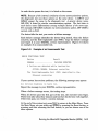
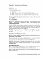
3.3 Main Menu Options
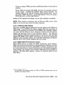
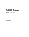
The Main Menu has six options, as shown in Figure 3-1. Choose an option
by typing the number and pressing IReturnl.
Figure 3-1: The Main Menu
MAIN
MENU
Release nnn
Version
xx.xx
1 - Test the System
2 - Display System Configuration and Devices
3 - Display the System Utilities Menu
4 - Display the Service Menu
5 - Display the Connect/Ignore Menu
6 - Select Single Device Tests
Type the number; then press the RETURN key. >
NOTE: The MDM release and version numbers are represented by nnn and
xx.xx in the sample screens provided throughout this chapter.
Option 4, "Display the Service Menu," is available only if you have
purchased the MicroVAX Maintenance Kit. The maintenance kit contains
service diagnostics and the system maintenance guide. Only qualified
service personnel should use the MicroVAX Maintenance Kit.
The next five sections describe the remaining options on the Main Menu.
3.3.1 Test the System
The "Test the System" option runs a quick, general test of the devices in
the system and how they work together. You can run the test at any time
without jeopardizing data.
When you select "Test the System," the diagnostics are prepared for testing.
If this is the first MDM option you have selected, the diagnostics are
automatically loaded. The loading process takes several minutes. When
the preparations and loading are complete, you are prompted to press IReturn L
A screen explaining the testing procedures then appears.
When you are ready to begin the test, press 1Return I. The "Begin Device Tests"
screen appears.
3-10 MicroVAX Troubleshooting and Diagnostics
As each device passes the test, it is listed on the screen.
NOTE: Because of the internal similarity of some communications options,
the diagnostic test sees these options as the same device. A DHVll and
DHQll appear the same to the diagnostic test. A generic device name,
DH-CXO, is listed for similar communications options. The last letter in
each device name differentiates among multiple devices of the same type.
For example, DH-CXOA indicates one communications option, DH-CXOB a
second, and so forth.
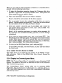
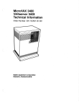
If a device fails the test, you receive a failure message.
Each failure message identifies the device being tested, when the failure
occurred, and the field replaceable unit (FRU). Copy the failure message
and report it to your DIGITAL service representative. Figure 3-2 shows
an example of an unsuccessful test.
Figure 3-2:
Example of an Unsuccessful Test
BEGIN FUNCTIONAL TEST
Device
Result
DEQNAA
FAILURE DETECTED
A failure was detected while testing the
OPTION: DEQNAA
Ethernet controller
The Field Replaceable Unit (FRU) identified is the:
Ethernet controller
If your system has serious problems, the following message may appear:
All devices disabled, no tests run.
Report the message to your DIGITAL service representative.
When a failure message occurs, the testing stops.
When all devices pass the first part of the test, the exerciser tests begin.
These tests take about four minutes and test how the devices work together.
If the tests pass, you receive a success message.
At the end of the system test, press IReturn I to return to the Main Menu. From
the Main Menu you can either exit MDM by pressing the Reset button, or
pressing and then releasing the Halt button, or you can choose one of the
other options.
Running the MicroVAX Diagnostic Monitor (MOM)
3-11
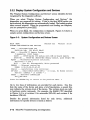
3.3.2 Display System Configuration and Devices
The "Display System Configuration and Devices" screen identifies devices
recognized by the diagnostic software.
When you select "Display System Configuration and Devices," the
diagnostics are prepared for testing. If this is the first MDM option you
have selected, the diagnostics are automatically loaded. The loading process
takes several minutes. When the preparations and loading are complete,
you are prompted to press 1Return I.
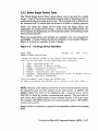
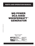
When you press 1Return I, the configuration is displayed. Figure 3-3 shows a
sample system configuration and devices screen.
Figure 3-3:
System Configuration and Devices Screen
MAIN MENU
SYSTEM CONFIGURATION AND DEVICES
Release nnn
Version
xX.xx
CPUA ... MicroVAX/rtVAX CPU
KA630-AA 1MB,
FPU MC~OO HW=OO
MEMA ... MicroVAX II Memory System
5 megabytes. 10240 Pages.
KA630 ... M7606-AA/EA CPU module with 1MB on-board memory
KA630-BB ... M7608-BA (MS630-BB) Memory module, quad height 4mb
RQDXA ... Winchester/diskette controller.
Revisions = 2 and 1
RD53 ... Unit #0, Nonremovable, Write protected
DEQNAA .,. Ethernet controller
DEQNA Q 08-00-2B-03-AC-DF
DZQ11A ... Asynchronous line controller.
DH-CXOA ... CXA16/CXB16/CXF32/DHF11 - 16 lines, No Modem control
ROM Rev: CONTROL = 16 OCTART = 1
TKXXA .. , TK50/TK70 CONTROLLER
TK-Q_REV MC=4
Press the RETURN key to return to the previous menu. >
Up to two lines of information are provided for each device. One line
lists the name of the device and gives a brief description, a second line
may indicate the revision level of the device. The revision level can refer
to hardware and/or microcode. For example, the KA630 CPU described
in Figure 3-3 is at revision 0 for microcode (MC=OO) and revision 0 for
hardware (HW=OO).
Besides the general information listed for each device, additional
information for specific devices is listed as follows:
3-12 MicroVAX Troubleshooting and Diagnostics
•
CPU -'- Type of CPU, presence of a floating-point unit (FPU).
•
MEM - Total amount of memory in megabytes and pages, number and
type of memory modules.
•
KFQSA - For systems with the KFQSA storage adapter, the type of
DSSI device and its unit number are displayed for each ISE.
•
DSIA - For systems with the KA640 CPU, the type ofDSSI device and
its unit number are displayed for each ISE.
•
RQDX - Type, unit number, and description of each mass storage
device connected to the controller.
•
DELQA, DEQNA, or DESQA - The Ethernet station a!idress.
•
NIA - The onboard Ethernet controller for systems with the KA640
CPU.
•
Communications devices modem control.
The type of device and whether it has
In addition to showing information about testable device options, MDM
displays messages indicating the presence of nontestable system devices.
If a device is physically present in the system but is not described under
the "System Configuration and Devices" display, one of the following two
messages can indicate the reason.
Message 1:
No Dg KAA ... Diagnostic not loaded
The "No Dg" (no diagnostic) "KAA" (KA630 CPUA) message appears in place
gfthe device name because a diagnostic was not loaded for the CPUA This
can happen when the media is not installed properly or the diagnostic is
not present on the media.
MDM displays a "No Dg" message for each DIGITAL device present in
the system under these circumstances. For example, if MDM cannot find
the TK70 tape drive diagnostic, the message "No Dg TKA" appears. TKA
indicates that the device is a TK tape drive.
Running the MicroVAX Diagnostic Monitor (MOM)
3-13
Message 2:
Unknown ... Diagnostic not loaded
The "Unknown" (unknown device) message indicates that a device not
recognizable to MDM has been attached to the system. The message
appears under the following circumstances:
•
A device is configured to a nonstandard CSR address.
•
A DIGITAL device that has no diagnostic has been attached to the
system. This may occur if a device not supported on a MicroVAX system
has been attached.
•
A non-DIGITAL device has been attached to the system.
Once all devices have been listed, you can return to the Main Menu by
pressing IReturn I.
To exit MDM, press IBreak I, the Reset button, or press and then release the
Halt button.
3.3.3 Display the System Utilities Menu
Choose "Display the System Utilities Menu" to display the System Utilities
Menu. If system utilities in addition to the "IOADDRES" option are
available for your system configuration, they are listed on the menu.
When you select this option, the diagnostics are prepared for testing. If this
is the first MDM option you have selected, the diagnostics are automatically
loaded. The loading process takes several minutes. When the preparations
and loading are complete, you are prompted to press IReturn!.
When you press IReturnl, the System Utilities Menu appears. Figure 3-4
shows a sample System Utilities Menu for a system with an RQDX
controller and two KRQ50 controllers.
NOTE: If your system does not have an RQDX controller or an RRD40 /50
Optical Disk Subsystem, only one option, IOADDRES, will be available.
3-14 MicroVAX Troubleshooting and Diagnostics
Figure 3-4:
Sample System Utilities Menu
MAIN MENU
SYSTEM UTILITIES
Utility selections are:
1
2
3
4
-
IOADDRES
RXAA - Disk drive formatter for RQDX controller A.
RRAA - Update drive unit number for RRD40 controller A.
RRAB - Update drive unit number for RRD40 controller B.
Choose the option by typing the option number listed on the menu and
pressing 1Return I.
3.3.3.1 IOADDRES
NOTE: The "IOADDRES" option is intended for users of Industrial VAX
systems.
This option is described in detail in the Industrial VAX
. Troubleshooting manual.
The "IOADDRES" option supplies a listing of standard Control and Status
Register (CSR) addresses and interrupt vectors that MDM uses in testing
devices. The first available CSR and interrupt vector for configuring devices
with a nonstandard address is also supplied.
The devices in your system were configured properly at the factory. Any
new options added to your system are configured properly in the field by a
DIGITAL service representative.
3.3.3.2 Customer Disk Drive Formatter
NOTE: RF-series Integrated Storage Elements are preformatted and cannot
be formatted by the customer.
If your system allows you to format RX33 diskettes, or to format fixed-disk
drives, use the following guidelines to make formatting easier.
CAUTION: Running the formatting utility destroys all data on the disk.
Use this utility only if you want to erase the contents of a disk and reinstall
system software.
Formatting Instructions
If you are formatting an RX33 diskette, remove the diskette's Write-Protect
tab, insert the diskette into the diskette drive, and lock the lever.
If you are formatting a fixed-disk drive, set the drive's Write-Protect button
to write-enable (out).
Running the MicroVAX Diagnostic Monitor (MOM)
3-15
When you are ready to begin formatting a diskette or a fixed-disk drive,
proceed with the following instructions:
1. To begin the formatting operation, choose the "Customer disk drive
formatter" option from the Systems Utilities menu. Write-protect all
drives except the one you want to format.
2. Type 1 and press IReturn I when you are ready to continue.
Result: A list of the unit numbers for the drives appears.
3. You are prompted to enter the unit number of the drive you want to
format. Type the number and press IReturn I. Verify that you have entered
the unit number of the drive that you want to format.
4. If the unit number is incorrect, type 0, press IReturn!, and re-enter the
unit number. If the unit number is correct, type 1 and presslReturnl. The
formatting operation begins.
Result: As the operation progresses, you receive status messages. At
the completion of a successful formatting operation, a success message
is displayed.
5. If you want to format another unit, type 1 and press IReturn!. The
formatting process will begin again. For example, if you want to format
another RX33 diskette, remove the diskette that you have formatted,
insert another diskette, and repeat the process from step 3. Otherwise,
type 0 and press IReturnl. The Utilities Menu displays.
6. To return to the MDM Main Menu, type 0 and press IReturn!.
To exit MDM, press IBreak 1, the Reset button, or press and then release
the Halt button.
3.3.3.3 Update Drive Unit Number for RRD40
This utility allows you to update the unit number for the RRD40 compactdisk subsystem. Refer to the RRD40 Disk Drive Owner's Manual for
instructions.
3.3.4 Display the Connect/Ignore Menu
NOTE: The "Connect / Ignore Menu" is intended for users of Industrial VAX
systems. The options in this menu are described in detail in the Industrial
VAX Troubleshooting manual.
The "Connect/lgnore Menu" options allow you to customize MDM
diagnostics. You can load your own diagnostics to a particular device, as
well as load MDM diagnostics to a device with a nonstandard CSR address
and interrupt vector.
3-16
MicroVAX Troubleshooting and Diagnostics
3.3.5 Select Single Device Tests
The "Select Single Device Tests" option allows you to run tests for a single
device. A test of the device's individual circuits, called a "functional test," is
performed during the single device tests. The functional test is followed by
an "exerciser test" to ensure that the device as a whole is working properly.
When you select the Single Device Tests from the Main Menu, the
diagnostics are prepared for testing. If this is the first MDM option you
have selected, the diagnostics are automatically loaded. The loading process
takes several minutes.
When the preparations and loading are complete, you are prompted to
press 1Return I. A screen listing the devices included in your system displays.
Figure 3-5 shows an example of such a display.
Figure 3-5: The Single Device Tests Menu
MAIN MENU
SELECT SINGLE DEVICE TEST
Release nnn
Test
xx.xx
Select the device number to be tested. The functional tests
will be run followed by the exercisers for 4 minutes.
1
2
3
4
5
6
7
-
CPUA - MicroVAX/rtVAX CPU
MEMA - MicroVAX II Memory System
RQDXA - Winchester/diskette controller.
DEQNAA - Ethernet controller
DZQIIA - Asynchronous line controller.
DH-CXOA - CXA16/CXB16/CXF32/DHFll-16 lines, No Modem control
TKXXA - TK50/TK70 CONTROLLER
Type the number; then press the RETURN key,
or type 0 and press the RETURN key to return to the Main Menu. >
NOTE: Because of the internal similarity of some communications options,
the diagnostic tests see these options as the same device. A DHVll and
DHQll appear the same to the diagnostic test. A generic device name,
DH-CXO, is listed for similar communications options. The last letter in
each device name differentiates among multiple devices of the same type.
For example, DH-CXOA indicates one communications option, DH-CXOB a
second, and so forth.
Select a device for testing by typing the corresponding number and pressing
IReturnl.
Running the MicroVAX Diagnostic Monitor (MDM)
3-17
When you press IReturn I, the system loads the device diagnostics and testing
begins. When the device passes the functional test, a message to that
effect displays, and the exerciser test begins. The exerciser tests run for
approximately four minutes. Figure 3-6 shows an example of a successful
test.
Figure 3-6: Example of a Successful Test
BEGIN FUNCTIONAL TEST
Device
Result
CPUA . . . . . . . . . . . . . . . . . . . PASSED
BEGIN EXERCISER TEST
Results are reported at the end of the testing.
SINGLE DEVICE TEST PASSED
If a device fails the test, you receive a failure message. Each failure
message identifies the device being tested when the failure occurred and
the field replaceable unit (FRU). Copy the failure message and report it to
your DIGITAL service representative. Figure 3-7 shows an example of an
unsuccessful test.
Figure 3-7: Example of an Unsuccessful Test
BEGIN FUNCTIONAL TEST
Device
Result
DEQNAA
FAILURE DETECTED
A failure was detected while testing the
OPTION: DEQNAA
Ethernet controller
The Field Replaceable Unit (FRU) identified is the:
Ethernet controller
Press IReturn I to return to the Single Device Menu for more testing.
To exit MOM, press IBreak I, the Reset button, or press and then release the
Halt button.
3-18 MicroVAX Troubleshooting and Diagnostics
3.3.6 Exiting MOM
Exit MDM by doing one of the following:
•
Press IBreakl.
•
Press and then release the Halt button on the operator control panel.
•
Press the Reset button.
Remove the RX50 diskette or tape cartridge, as explained in your systemspecific Operation manual.
If you have run MDM on a new system, you are ready to install your system
software. Follow the instructions in your system software manuals. If you
have used the Disk Formatter Utility to format a fixed disk or a diskette,
you must reinstall system software. Set the Write-Protect button to writeenabled and install system software.
If you have run MDM on a system containing system software, you must
reboot your system software.
You can reboot your system software in two ways.
•
At the console mode prompt »>, use the command BOOT Dxxx, where
Dxxx is the device name of the fixed disk or RF -series ISE containing
your system software. (Use DUxx if this is an RD-series disk drive, RAseries disk drive, or an RF-series ISE (with the KA640 CPU). Use DIxx
if this is an RF-series ISE (with the KFQSA storage adapter.» After
the system software is loaded, set the Break EnablelDisable switch to
disable, indicated by the dot outside the circle, to avoid inadvertently
halting the system by pressing the I Break I key.
•
Set the Break Enable/Disable switch to disable and press the Reset
button. This causes your system to begin the power-on sequence again
and automatically load system software.
Running the MicroVAX Diagnostic Monitor (MDM)
3-19
Appendix A
Diagrams for Locating Controls on Your
MicroVAX System
The diagrams in this appendix are to aid in locating the controls on your
system that may be referenced during troubleshooting procedures.
Diagrams for Locating Controls on Your MicroVAX System A-1
Figure A-1:
MicroVAX II 630QY
Controls and Indicators
mamaama
MaoVAX
II
I
0
ON/OFF
SWITCH
~
Run
HALT
BUTTON
DeOK
0
0
Halt
Restart
0
0
F.ixed Disk 0
Write Protect
RESTART
BUTTON
Ready
G
WRITEPROTECT
BUTTONS
DCOK
LIGHT
READY
BUTTON
CIRCUIT'
BREAKER
POWER-UP
MODE
SWITCH
BAUD RATE
SWITCH
HALT
ENABLE/
DISABLE
SWITCH
CONSOLE
TERMINAL
CONNECTOR
LED
DISPLAY
MLO-000437
'Reset the circuit breaker by pushing it in.
Diagrams for Locating Controls on Your MicroVAX System A-3
FlgureA-2:
MlcroVAX II 630QB
Controls arid Indicators
RESTART/RUN
De OK
LIGHT --I~
OPTIONAL
FIXED-DISK
DRIVES
HALT
BUTTON
WRITE
PROTECT - - - - l . r - l
BUTTON
READY
BUTTON
LED
DISPLAY
HALT
ENABLE/
DISABLE
SWITCH
-+--tH
POWER-UP
MODE
-I--..-{
SWITCH
BAUD RATE-I-----f
SWITCH
CONSOLE TERMINAL
CONNECTOR
CIRCUIT*~
I
BREAKER
*Reset the circuit breaker by pushing it down and then lifting it to the up position.
~
MLO""()()()438
Diagrams for Locating Controls on Your MicroVAX System A-5
Figure A-3:
mamaama
Fixed Disk 0
Write Protect
Halt
~
[g]
Ru,
MiauVAX
II
0
MicroVAX II 630QE
Controls and Indicators
~B ID"A"I~GJGJ
Restart
Ready
g
~
DC OK
0
0
Fixed Disk 1
ON/OFF
SWITCH
Wnte Protect
[g]
I,
iii
Ready
~
I~GlIIJl
ii'
DC OK
I!i
0
HALT
ENAB LE/
DISABLE
SWITCH
LED
DISPLAY
POWER-UP
MODE
SWITCH
BAUD RATE ~_--'
SWITCH
CONSOLE
TERMINAL
CONNECTOR
SYSTEM CIRCUIT BREAKER'
POWER CORD
cf'
(fJ
MAIN POWER
(fJ
(fJ
(fJ
MlO-OOO439
'Reset the circuit breaker by pushing it down and then lifting it to the up position.
Diagrams for Locating Controls on Your MicroVAX System A-7
Figure A-4:
MicroVAX 3300
Controls and Indicators
OPERATOR CONTROL PANEL
DRIVE
Unit Number
~ g] ~
Fault
c::::J
WriteProtect
Gl
G1
Ready
SYSTEM
c::::J
c::::J
E] E]
E] G1
IE] Gl I I
c::::J
Restartl
RUn
DC OK
LIGHT
RESET
BUnON
f
0.+ CIRCUIT"
BREAKER
"Reset the circuH breaker by pushing Hin.
Hall
=]
LED
DISPLAY
BREAK
ENABLE!
DISABLE
SWITCH
STANDARD
ETHERNET
CONNECTOR
POWER-UP
MODE
SWITCH
MODIFIED
MODULAR
JACK
ETHERNET
CONNECTOR
SWITCH
THINWIRE
ETHERNET
CONNECTOR
,
ML()'OO0723
Diagrams for Locating Controls on Your MicroVAX System A-9
Figure A-5:
MlcroVAX 3400
Controls and Indicators
OPERATOR CONTROL PANEL
DRive
Unit Number
Fault
WriteProtect
Ready
Q] ~
fm
C=:J C=:J C=:J
GJ G G
GJ G G
SYSTEM
IG
Restart!
Run
G
IC=:JI
Halt
==
I
.
DC OK
~ t- LIGHT
~
i-
l"- RESET
BUTTON
CIRCUIT"
BREAKER
·Reset the circuH breaker by pushing Hin.
LED
DISPLAY
BREAK
ENABLEI
DISABLE
SWITCH
STANDARD
ETHERNET
CONNECTOR
POWER-UP
MODE
SWITCH
MODIFIED
MODULAR
JACK
ETHERNET
CONNECTOR
SWITCH
THINWIRE
ETHERNET
CONNECTOR
MLO-OOO724
Diagrams for Locating Controls on Your MicroVAX System
A-11
Figure A-6:
IRun
0
2
~~
~
I
~
SOl-Based MicroVAX 3500
Controls and Indicators
Fault
Ready
WriteProtect
A
B
•
•
§
•
•
•
•
•
•
I
10
Halt
OR
I t::iW
I
era
3 l i t - - - ON/OFF
SWITCH
'---~I---_ DC OK
~
LIGHT
~~
I ,RESTART
BUTTON
BREAK
ENABLE!
DISABLE
SWITCH
POWER-UP
It:=::;~+,-- MODE SWITCH
LED
!+----;-- DISPLAY
[..'1--+_
.r
At
CIRCUIT'
BREAKER
MODIFIED
MODULAR
JACK
'Reset the circuit breaker by pushing it in.
Diagrams for Locating Controls on Your MicroVAX System
MLO-000440
A-13
Figure A-7: DSSI-Based MlcroVAX 3500
Controls and Indicators
OPERATOR CONTROL PANEL
[ill~Q]
DRIVE
Unit Number
c:::J c:::J c:::J
FauH
BGG
Wrtt.Protect
131313
Ready
I G ElIc:::J1
=1
SYSTEM
"e.tart/
HIIH.
Run
BREAK
~DCOKLIGHT
@-+-RESET
BUnON
o
ENABLE!
DISABLE
SWITCH
*Reset circuit breaker by pushing it in.
@
(J;)
SWITCH
LED~I
DISPLAY
'--+-CIRCUIT*
BREAKER
~
~~:it=)1
5~ j POWER-UP
6 -I>~---- MODE·
I
~~
~
MODIFIED
MODULAR
JACK
MLO-002396
Diagrams for Locating Controls on Your MicroVAX System A-15
Figure A-8: MicroVAX 3600 Controls
and Indicators, Front View
Em:
I
Run
0
2
~
I
~
Fault
Ready
WriteProtect
•
§
•
•
•
A
B
•
•
•
I
10
•
Hah
OR
I u:::J
I
f':m[E
'---~l-- DC OK
LIGHT
~~,RESTART
I
BUTION
BREAK
ENABLE!
DISABLE
SWITCH
POWER-UP
(t:=::J1+'-- MODE SWITCH
LED
--';--DISPLAY
_C;;f
....-t-_CIRCUIT.
.r
BREAKER
'Reset the circuit breaker by pushing it in.
MODIFIED
MODULAR
JACK
-.,
MLO·OOO441
Diagrams for Locating Controls on Your MicroVAX System
A-17
i.o
Figure A-9:
MicroVAX 3600 Controls
and Indicators, Rear View
SYSTEM CIRCUIT BREAKER'
POWER CORD
cf'
e
DEC POWER CONTROL BUS
~~
J9'-/JlO
@
CABLE
SHIELD,!. 0
o
~~0
J11'/J12
@
CABLE
SHIELD.!.
I
A-~-B
• Reset the circuit breaker by pushing it down and then lifting it to the up position
MlO-OOO442
Diagrams for Locating Controls on Your MicroVAX System
A-19
Figure A-10:
MicroVAX 3800
Controls and Indicators
OPERATOR CONTROL PANEL
~[grm
DRIVE
Unit Number
c::::::J c::::::J c::::::J
Fautt
BElGl
Write-
Protect
GGG
Rnd,.
IGGIc::::::Jj
SYSTEM
fl.....rt!
Halt
llun
=1
BREAK~
ENABLEI
DISABLE
SWITCH
~~:il1.:J1
5~ J POWER-UP
6 ~~~MODE
©
(V
LED~
~~
DISPLAY
f
C>-+-CIRCUIT·
BREAKER
·Reset circuit breaker by pushing it in.
SWITCH
,.
~
MODIFIED
MODULAR
JACK
MLO·002396
Diagrams for Locating Controls on Your MicroVAX System
A-21
Figure A-11:
MlcroVAX 3900 Controls
and Indicators, Top Front View
FOUR-CHARACTER ~
ALPHANUMERIC
STATE LED
I~
r "====-=",::!:J
INDICATORs~--I-I-
RUN SWITCH
, U N I T NUMBER
DIS~I
-I
I
I
TEST SWrrcH
.
PORT B SWITCH
FAULT SWITCH
.
PORT A SWITCH
WRITE PROTECT SWITCH - - - - - - - - - '
RA70 OPERATOR CONTROL PANEL
I
Run
Fauft
Ready
0
0
:
::
WriIII-
A
B
0
0
0
0
0
0
Protect
I
IIJ
Halt
0
I
MLQ-002397
Diagrams for locating Controls on Your MicroVAX System A-23
Figure A-12:
f
0-
MicroVAX 3900 Controls
and Indicators, Bottom Front View
CIRCUIT*
BREAKER
BREAK
ENABLE!
DISABLE
SWITCH
~
~w...:ifl
5~__
J POWER-UP
6 -I>@
MODE SWITCH
@
G:>
LED
DISPLAY
MODIFIED
MODULAR
JACK
*Reset ciruit breaker by pushing it in.
MLQ.O02398
Diagrams for Locating Controls on Your MicroVAX System A-25
Figure A-13:
MicroVAX 3900 Controls
and Indicators, Rear View
SYSTEM CIRCUIT BREAKER'
POWER CORD
cf'
e
e
DEC POWER CONTROL BUS
~EP€3€30
J9'/J10
CABLE
MAIN PQWEH
'"
SHIElD6
o
J11,/j12
CABLE
0
'"
SHIELO~
A~~-B
e
'Reset the circuit breaker by pushing it down and then lifting it to the up position.
e
MLO-000442
Diagrams for Locating Controls on Your MicroVAX System A-27
Index
F
A
Autobooting the MicroVAX system,
1-1
c
Connect/Ignore
option on the Main Menu, 3-16
D
Disk Drive Formatter
option on System Utilities Menu,
3-15
Diskless and tapeless systems
using the MicroVAX Ethernet
Server Customer
Diagnostics Kit, 3-2
Diskless and Tapeless Systems
running MDM on, 3-2
Display System Configuration and
Devices
option on Main Menu, 3-12
Display the System Utilities Menu
option on Main Menu, 3-14
Dual-host systems
running MDM on, 3-3
E
Error messages
all devices disabled, 3-11
No Dg, 3-13
Unknown, 3-14
Exiting MicroVAX Diagnostic
Monitor (MDM), 3-19
Fixed Disks
operation problems, 2-3
problems booting from, 1-4
IOADDRES
option on Main Menu, 3-15
ISE
See RF-series integrated storage
element
M
Main Menu
of MicroVAX Diagnostic Monitor
(MDM), 3-10
MDM Hard Disk Kit, 3-3
MicroVAX Diagnostic Monitor
(MDM)
description, 3-1
medium containing, 3-1
running, 3-1
starting, 3-6
when to run, 3-1
MicroVAX Diagnostic Monitor
Ethernet Server User's Guide
diskless and tapeless systems use
of, 3-3
MicroVAX Ethernet Server Customer
Diagnostics Kit
included with diskless and
tapeless systems, 3-2
p
Power-on problems, 1-1
~...
Index-1
R
u
RA60/70/81/82 disks
operation problems, 2-2
RA90 disks
booting from, 1-9
operation problems, 2-2
Rebooting the system
after running MDM, 3-19
RF-series integrated storage
elements
booting from, 1-10
operation problems, 2-3
RX50 diskette drives
operation problems, 2-4
problems booting from, 1-10
running MDM on, 3-6
Utilities Menu
option on Main Menu, 3-14
s
Self-test
during power-on, 1-1
Single Device Tests
option on the Main Menu, 3-17
Starting the MicroVAX Diagnostic
Monitor (MDM), 3--5
from a TK50frK70 tape cartridge,
3-7
from RX50 diskettes, 3-6
T
Test the System
option on Main Menu, 3-10
TK50 tape drives
operation problems, 2-6
problems booting from a tape
cartridge, 1-11
running MDM on, 3-7
TK70 tape drives
operation problems, 2-5
problems booting from a tape
cartridge, 1-11
running MDM on, 3-7
Troubleshooting
during normal operation, 2-1
Index-2
w
Write-protecting disks
during formatting, 3-16