1
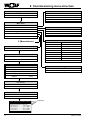
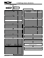
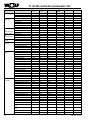
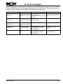
9. Settings menu structure
F (Manufacturer)
Contractor
Parameter
Password
1234
Configuration
Num.of circuit
Num.of compressor
Num.of capacity
Setting
2
2
1
Compressor time set
Range
1/2
1-4
1/2
Range
Min. ON time
Min. OFF time
Start delay
Max. work time
0 min
6 min
2 min
30000 h
Press. level set HP
Exp.board present?
HP
No
0 - 99
0 - 99
0 - 99
100099000
HP - LP
No/Yes
Press. level set high pressure
Comp.block
20.0 bar
Comp.deactive
23.0 bar
Stop delay
10 s
Range
0 - 99
0 - 99
0 - 99
Press. level set low pressure
Comp.block
4.0 bar
Comp.deactive
3.0 bar
Stop delay
10 s
Range
0 - 99
0 - 99
0 - 99
Low press. alarm
Startup delay
90 s
Part-winding time
500 ms
I/O configuration
Range
0 - 9999
0 - 9999
Range
Analog input
HP transducer circuit1
Position:
Min./max. limit:
Offset:
4-20 mA
V. signals
30 bar
0.0 bar
00.0 - 99.9
-9.9 - 9.9
Range
Analog input
3063613_201307
Range
LP transducer circuit1
Position:
Min./max. limit:
Offset:
06
4 - 20 mA
V. signals
10 bar
0.0 bar
00.0 - 10.0
-9.9 - 9.9
I/O configuration
Range
Analog input
LP transducer circuit2
Position:
Min./max. limit:
Offset:
07
4 - 20 mA
V. signals
10 bar
0.0 bar
00.0 - 10.0
-9.9 - 9.9
I/O configuration
Range
Analog input
External
0 - 10 V
Capacity regulation 01
0 - 10 V
Min./max. limit:
Offset:
100 %
0.0 %
V. signals
00.0 - 999.9
-9.9 - 9.9
Information
Software information
Information
Hardware information
Initialization
Insert new manufacturer
Password (PW2) 1 2 3 4
I/O configuration
Digital input and output settings
only through factory service after entry of password
HP transducer circuit2
Min./max. limit:
Offset:
Setting
02
I/O configuration
Position:
I/O configuration
Analog input
03
4-20 mA
V. signals
30 bar
0.0 bar
00.0 - 99.9
-9.9 - 9.9
11