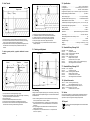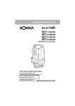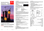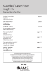
1
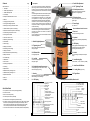
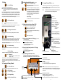
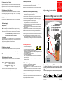
21. Automatic Laser Cut-Out
27. Setting the Direction
The kick guard can be activated if wanted via the menu. It is active, as soon as a T
appears in the status display. This means the laser is switched off automatically as
a precautionary measure in the event of a jerky movement (bump). The T then
begins to blink. The laser beam must then be switched on again by briefly pressing
the On button and the positioning checked and corrected if necessary.
When the inclination has been set, align the laser roughly on the target point
with the mounting device and then finely with the buttons.
The direction can also be set with the remote control VF-80. To avoid unwanted
adjustment, the lock and respective arrow button must be pressed simultaneously to set the direction.
22. Monitoring of Self-Levelling
The self-levelling function corrects even the smallest deviation. At a deviation of
approx. 0.01 % the laser beam and laser beam symbol begin to blink. Depending
on the setting, blinking can start earlier at approx. 0.005 % or later at approx.
0.015 %.
23. Flicker Mode
Flickering makes the laser beam significantly easier to see in unfavourable light
conditions.
24. Power Supply
220 V Operation
Connect the drifting laser to the power supply type NE-12/2A.
Note: The laser may not be connected directly to the battery of a running
engine or to a charging device. Also make sure that the housing of the laser
does not come into direct contact with the poles of the battery or with the body
work of a motor vehicle.
In the case of welding work care must be taken to ensure that
the current cannot flow through the laser:
Disconnect all cable connections to the laser!
12 V Operation
Connect the laser to a 12 V rechargeable battery or energy box type EB-12/24
(48.01) with the battery connector (47.00). Make sure that the red terminal is
connected to the plus pole and the black terminal to the minus pole. Incorrect
polarity will not damage the laser, but the laser will not work.
Operating Instructions
28. Automatic Direction Adjustment/Locking
1. Install the drifting laser VL-80 in standing or suspended position using the
positioning device. Level the box level (see 7.).
2. Connect the power supply to the laser and remote control.
3. Centre the device on middle position by pressing the arrow up and arrow
down buttons at the same time.
4. Set the inclination of the target beam. Set the direction axis roughly by
turning the laser and finely with the direction arrow buttons.
5. Set the locking laser beam on the required height.
6. Install the receiver with the switch setting "Manual Side" so that the
locking laser beam falls on the centre of the solar cell cover.
7. Connect the locking receiver and VL-80 with the connection cable (74.25)
and then open the solar cell cover.
8. Switch the drifting laser VL-80 off and then back on again to activate the
locking receiver.
9. Adjust the direction of the solar cell unit with the knurled knob by hand until
the green LED indicates middle position.
10. Switch the switch to "Auto On", thus activating the automatic direction
function.
11. Check the direction of the target beam and correct with the knurled knob on
the locking receiver if necessary.
12. The status "No Reception" and "Automatic Off" are shown in the LCD
display of the laser (see 9.1) and on the remote control VF-80 by an LED
and additionally by an acoustic signal. The volume can be adjusted with the
keyboard.
Note:
Automatic-Drifting Laser VL-70/-80
Fixing the line - locked on target!
1
2
3
4
1
FE PHVL VF -
80
80
80
80
2
Loc
k
ing
bea
m
Proceed in the above order!
3
29. Safety Instructions
25. Setting the Inclination
The laser beam is set at a defined inclination with the arrow up / down buttons.
Note:
The gradient/inclination is shown in %, not in degrees or gon.
The defined inclined directional beam refers to the automatic levelling of the
laser.
26. Calculating the Percentage
If the percentage value that is to be set is not known, it can be calculated as
follows:
Example: Height difference between 2 points = 0.2 m
Length
between 2 points = 50 m
Height difference x 100
0.2 x 100
-------------------------------- = -------------- = 0.4 %
Length
50
Convert % to ‰ - move the decimal point one place to the right.
Convert ‰ to % - move the decimal point one place to the left.
•
•
•
•
•
•
•
•
System components
Locking receiver
Positioning device
Drifting Laser
Remote control
Pay attention to the accident prevention regulations.
Do not set up the laser at eye level.
Do not look into the beam.
Do not remove the warning signs on the laser.
Check the laser before every use (control measurement).
The manufacturer and its dealers accept no liability for damage caused by faults
and consequential damages.
Only use the battery charger in dry rooms.
Do not open the laser yourself.
Note: The laser power values in the device are far higher than prescribed for
laser class 2 or 3B.
Repairs requiring the device to be opened may only be carried out by
authorized persons.
!
Ta r
g
et b
eam
4
30. Troubleshooting
1. No laser beam - check power supply; low battery?
2. Low range - clean laser beam exit window.
3. Laser beam blinks slowly - move device into the levelling range by tilting
forwards.
If the error is not corrected within 2.5 minutes, the device is switched off
automatically.
4. Laser switched off automatically (kick guard) - switch on the device again.
Congratulations on your new GEO laser
In addition to information on how to use the laser, these
operating instructions also contain important safety instructions.
Read the operating instructions carefully before using the laser.
31. Maintenance
The laser requires no special maintenance. Keep the electrical connections clean.
Do not clean with water spray. Clean glass parts with a soft, clean cloth. Store dry.
Always transport the laser in its original case.
Solinger Straße 8 • D-45481 Mülheim • Tel.: 02 08 / 9 93 57-0 • Email: [email protected]
Edition 04/2006
7
8
Subject to change
Contents
Page
Quick Start Guide . . . . . . . . . . . . . . . . . . . . . . . . . . . . . . . . . . . . . . . . . . . . . . . 1
1. Description . . . . . . . . . . . . . . . . . . . . . . . . . . . . . . . . . . . . . . . . . . . . . . . . . 2
2. Parallel Height Adjustment . . . . . . . . . . . . . . . . . . . . . . . . . . . . . . . . . . . . . 2
4. Parallel Side Adjustment . . . . . . . . . . . . . . . . . . . . . . . . . . . . . . . . . . . . . . 3
9.1 LCD Display . . . . . . . . . . . . . . . . . . . . . . . . . . . . . . . . . . . . . . . . . . . . . . . . 2
9.2 Adjustment Possibilities, Menu Level 2 . . . . . . . . . . . . . . . . . . . . . . . . . . . 3
13. Buttons . . . . . . . . . . . . . . . . . . . . . . . . . . . . . . . . . . . . . . . . . . . . . . . . . . . . 4
14. Changing the Factory Defaults . . . . . . . . . . . . . . . . . . . . . . . . . . . . . . . . . . 4
15. Locking Beam Height Adjustment . . . . . . . . . . . . . . . . . . . . . . . . . . . . . . . 5
16. Switching the Locking Laser Beam On/Off. . . . . . . . . . . . . . . . . . . . . . . . . 5
17. Receiver Status Symbols in LCD Display. . . . . . . . . . . . . . . . . . . . . . . . . . 5
18. Remote Control Status Symbols in LCD Display . . . . . . . . . . . . . . . . . . . . 5
19. VF-80 Drifting Laser Remote Control . . . . . . . . . . . . . . . . . . . . . . . . . . . . . 5
20. Locking Receiver FE-80 . . . . . . . . . . . . . . . . . . . . . . . . . . . . . . . . . . . . . . . 6
21. Automatic Laser Cut-Out . . . . . . . . . . . . . . . . . . . . . . . . . . . . . . . . . . . . . . 7
1.
4. Parallel Side Adjustment
Description
The VL-80 is a special laser especially developed for
pipe driving, but which can also be used for many other
purposes. It emits an automatically levelled or defined
inclined target beam and a second beam for direction
locking.
The advantageous diode laser beam features low power
consumption with immense target beam laser power.
It can be adjusted in five steps from 1 to < 5 mW for different requirements. The clearly visible locking beam is
equipped with automatic laser output power optimisation.
The laser has control indicators with blinking warning
system for levelling, direction locking, low battery and
end positions as well as a shift guard for the inclination
and direction setting.
The values that have been set remain stored in the laser
even after switching off or in the case of a low battery.
The name of the owner can be saved in the device to
protect against theft.
The VL-70 differs from the VL-80 in that it does not have a
direction locking feature.
4.2 Side Adjustment Screw
Note: Loosen the fastening srew before
adjustment, then tighten again.
4.3 Fastening Screw
Note: Loosen before side adjustment, then
tighten again.
5. Power Supply
12 V DC/ 0.4 A
6. Receiver/Remote Control Connector
7. Box Level
Set up aid, for viewing from above.
8. Keyboard
Clear layout, big, user-friendly, self-explanatory
keys.
22. Monitoring of Self-Levelling . . . . . . . . . . . . . . . . . . . . . . . . . . . . . . . . . . . . 7
23. Flicker Mode . . . . . . . . . . . . . . . . . . . . . . . . . . . . . . . . . . . . . . . . . . . . . . . . 7
4.1 5/8" Tightening Thread
2. Parallel Height Adjustment
9. LCD-Display
24. Power Supply . . . . . . . . . . . . . . . . . . . . . . . . . . . . . . . . . . . . . . . . . . . . . . . 7
2.1 Tightening Screw
Note: Loosen before height adjustment,
then tighten again.
Clearly legible, illuminated display for on/off,
company data, device data, inclination,
operating status and battery level.
28. Automatic Direction Adjustment/Locking . . . . . . . . . . . . . . . . . . . . . . . . . . . 8
2.2 Millimetre Rule
10. Handle
29. Safety Instructions . . . . . . . . . . . . . . . . . . . . . . . . . . . . . . . . . . . . . . . . . . . . 8
For height adjustment.
25. Setting the Inclination . . . . . . . . . . . . . . . . . . . . . . . . . . . . . . . . . . . . . . . . . 7
26. Calculating the Percentage . . . . . . . . . . . . . . . . . . . . . . . . . . . . . . . . . . . . . 7
27. Setting the Direction . . . . . . . . . . . . . . . . . . . . . . . . . . . . . . . . . . . . . . . . . . 8
30. Troubleshooting. . . . . . . . . . . . . . . . . . . . . . . . . . . . . . . . . . . . . . . . . . . . . . 8
31. Maintenance . . . . . . . . . . . . . . . . . . . . . . . . . . . . . . . . . . . . . . . . . . . . . . . . 8
32. Axis Transfer . . . . . . . . . . . . . . . . . . . . . . . . . . . . . . . . . . . . . . . . . . . . . . . . 9
for easy handling, safe transport and simple
set-up.
2.3 Lock Nut
11. Laser Warning Sign
Loosen before height adjustment,
then tighten again.
Laser class 3R, £ 5 mW, ³ 25 W/m² (see 29.)
33. Checking and Adjustment . . . . . . . . . . . . . . . . . . . . . . . . . . . . . . . . . . . . . 10
34. Checking . . . . . . . . . . . . . . . . . . . . . . . . . . . . . . . . . . . . . . . . . . . . . . . . . . 10
2.4 Height Adjustment Screw
12. Laser Beam Exit Window
35. Specifications. . . . . . . . . . . . . . . . . . . . . . . . . . . . . . . . . . . . . . . . . . . . . . . 11
Loosen tightening screw 2.1 and lock nut 2.3,
then set the height by turning.
12.1 Locking Beam (only VL-80)
3. Housing
12.2 Target Beam
36. Standard Delivery Package VL-80. . . . . . . . . . . . . . . . . . . . . . . . . . . . . . . 11
37. Standard Delivery Package VL-70. . . . . . . . . . . . . . . . . . . . . . . . . . . . . . . 11
38. Optional Accessories . . . . . . . . . . . . . . . . . . . . . . . . . . . . . . . . . . . . . . . . . 11
39. Service. . . . . . . . . . . . . . . . . . . . . . . . . . . . . . . . . . . . . . . . . . . . . . . . . . . . 11
Robust light-metal housing, plastic-coated, swept and
filled with nitrogen, 100 % watertight.
40. Disposal . . . . . . . . . . . . . . . . . . . . . . . . . . . . . . . . . . . . . . . . . . . . . . . . . . . 11
9.1 LCD Display
Quick Start Guide
1 Set up the laser on line at the required height (see 32.).
2. Connect the cables.
3. Switch on the laser (see 13.1).
4. Set the required inclination (see 13.2).
5. Set the direction of the target beam (see 13.4 and 27.).
6. If necessary, switch on the locking laser beam (only VL-80). Press the button
Menu/OK. The pointer appears in the display. Press Arrow Up / Down to
switch on the locking laser beam and to set the height (see 15. und 16.)
Then, for example, lock the beam with the receiver FE-80 (see 20.).
7. The remote control VF-80 can be connected for operation if wanted (see 19.).
1
9.2 Adjustment Possibilities, Menu Level 2
Lock symbol open / closed
Algebraic sign
Inclination value
Percent sign
Status symbols
Initialising
Adjusting inclination
Inclination adjustment finished
Power saving mode
Kick guard active
Blinks after jerky movement.
laser beam off
E = Sensitivity (see 23.)
T = Kick guard (see 21.)
(siehe 21.)
P = Percent/ Per mil
V = Lock
(see 13.7)
(siehe 13.7.)
F = Flicker
(see 23.)
(siehe 22.)
L = Laser power
W = Factory defaults
S = Service / Workshop information
Factory defaults
On
1 = Laser class 2
1 - 5:
2 - 5 = Laser class 3R
off
| Inclination or
+ Inclination and direction
% or ‰
Power supply indicator
Receiver status symbol (see
17.)
(siehe
17.)
Direction limitation
Centring indicator
Direction arrow
Centre indicator
Laser beam symbol
Remote control status symbol(siehe
(see 18.)
2
Off
1 -3 approx. 5 - 15 mm/100m
3
13. Buttons
15. Locking Beam Height Adjustment (only VL-80)
Menu
OK
= 13.1 On/Off Button
The device is switched on by pressing this button.
Note: If the laser is to be used with direction locking, the device must be
connected to the locking receiver and remote control before being
swiched on.
The device and company data are then shown, followed by the operating display
with the last settings without button lock. The device is then levelled and
referenced on the zero point automatically. After the levelling phase the laser
beam and laser beam symbol stop blinking. If this does not happen, the device
must be moved into the levelling range by tilting it forwards. To switch off the
device, press the On/Off button until "Auf Wiedersehen!" appears.
A direction arrow appears in the display. Long pressing
changes the locking beam height with increasing speed
until the direction arrow begins to blink. The height then
changes without the button having to be pressed until
the locking beam hits the receiver, a direction arrow is
pressed or end position is reached (blinking direction
arrow changes to a square).
or
Automatik-Kanalbau-Laser
KL-80/-81
= 13.2 Inclination Setting
or
The gradient/inclination is shown in % or ‰ , not in degrees
or gon.
Pressing the arrow button changes the inclination value by 0.001 %. The value is
changed with increasing speed if the button is kept pressed.
Press 1 x until the "Pointer" appears.
The external remote control and automatic direction
setting function do not work!
20. Locking Receiver FE-80 (only VL-80)
The FE-80 locking receiver makes monitoring and automatic locking of the
target beam possible. The integrated LED indicators are used for set-up and
status control. Installation see 27.
Note:
The FE-80 is not intended for calibration of the direction axis.
This must be done directly with the target beam!
Quick Setting
Spirit Level
for upright assembly
In addition to the respective arrow button also press the
Menu
OK
Back to operating display.
LED Position Indicator
green LED: centre posititon,
direction locking OK
red LED:
off-centre position
running light: no reception
2 LEDs constantly on:
measuring range
exceeded
Note:
16. Switching the Locking Laser Beam On/Off
(only VL-80) (only when working without locking receiver)
Menu
OK
+
= 13.3 Setting Inclination on Zero
The inclination value is set on 0.000 % by pressing the two arrow buttons at
the same time.
= 13.4 Direction Setting
or
After setting one of the two arrow buttons the laser beam symbol changes to an
arrow. It indicates the direction of movement and the current position. When
end position is reached, the laser beam and limitation symbol begin to blink.
The setting must then be moved back within 2.5 minutes. If this is not done, the
laser is switched off automatically.
= 13.5 Direction Centring
+
After pressing the two arrow buttons the device is automatically centred in
middle position.
13.6 Quick Setting
Press 1 x until the "pointer" appears.
The remote control does not work!
The locking laser beam can be switched on/off by long
pressing of the button.
Menu
OK
Back to operating display.
= 13.7 Button Lock
(alternatively inclination or inclination + direction
see 9.2; V = Lock)
ü = direction locking OK
E = no connection (check cable connections)
= not run in (refraction or oscillations)
? = no reception (obstacle in beam path)
| = direction locking switched off on receiver
= operation without receiver
ü = remote control OK
E = no connection (check cable connection)
= when button is pressed.
Keep the button pressed until the adjustment possibilities shown in 9.2
or
Solar Cell Cover
with target marking for set-up
Socket
for connection to the VL-80.
19. VF-80 Drifting Laser Remote Control
For direction setting of the target beam and locking beam, for
height setting of the locking beam, for visual and auditory status.
Laser Control LED
blinks in time with the target beam
Error LED
off: system working properly
on: direction locking faulty (see 17.) Kick guard actuated
14. Changing the Factory Defaults
= 14.1. Select Menu Level
Solar Cell Square
receives the locking laser beam from
the VL-80.
18. Remote Control Status Symbols in LCD Display
Press the button 2 x: the lock symbol begins to blink, press arrow up or arrow
down button. The buttons are protected against accidential adjustment.
Press the Menu button 2 x again, press the arrow up or arrow down button. The
lock is lifted.
Menu
OK
Knob
To move the solar cells for transfer of
the direction axis to the centre of the
solar cells.
Note: When automatic direction
setting is on, the direction axis
of the main beam is changed!
17. Receiver Status Symbols in LCD Display (only VL-80)
In addition to the respective arrow buttons also press the On/Off button.
Menu
OK
Direction Locking Toggle Switch
up: automatic direction setting off
down: automatic direction setting on
Socket
for connection
to the VL-80.
= 14.2 Select Letter
Alarm
An intermittent alarm is emitted 5 sec. after the error LED lights up. This
changes to a continuous alarm after 2 min. The intermittent alarm stops when
the error is corrected. The continuous alarm must be stopped by pressing the
volume button.
The selected letter begins to blink.
or
Alarm Volume / Clear Alarm
Adjustable in 4 steps: off, quiet, middle, loud
= 14.3 Change Settings
= 14.4 Back to Operating Display
4
Direction Setting for Target and Locking Beaml
To avoid operating errors, press the arrow and lock
button at the same time.
5
Locking Beam Height Adjustment (only VL-70)
Long pressing changes the locking beam height with increasing speed.
6
32. Axis Transfer
35. Specifications
7
Ausgangspunkt
Datum
Locking beam: . . . . . . . . . . . . . . . . . . . . . . . . . . . . class 2, < 1mW, red 635 nm
Locking beam Ø: . . . . . . . . . . . . . . . . . . . 5 mm at laser, approx. 13 mm at 15 m
Target beam (only VL-80):. . . . . . . . . . . . . . . . . . class 3R, < 5 mW, red 658 nm
Target beam core Ø (only VL-70): 13 mm at laser, + approx. 5.5 mm per 100 m
Range depending on ambient conditions: . . . . . . . . . . . . . . . . . . . . up to 500 m
Zielpunkt
Aim
point
Alignment
line
Fluchtschnur
nd
2. Lotung
1st plump
1. Lotung2 plump
M
8
Direction setting range: . . . . . . . . . . . . . . . . . . . . . . . . ± 5 % (10 m over 100 m)
Automatic direction function (only VL-70): . . . . . . . . . in combination with FE-80
Distance between VL-80 and FE-80: . . . . . . . . . . . . . . . . . . . . . . . . . 2 to 15 m
Inclination adjustment range locking beam (only VL-70):. - 2.5 % to 110 % (48°)
9
10
Inclination adjustment range target beam: . . . . . . . . . . . . . . . . - 10 % to + 40 %
Reading accuracy: . . . . . . . . . . . . . . . . . . . . . . . . . . . . . . . . . . . . . . . . . 0.001 %
Permissible deviation: . . . . . . . . . . . . . . . . . . . . . . . . . . . . . . . . . . . . . ± 0.005 %
Adjustment: . . . . . . . . . . . . . . . . . . . possible without having to open the device
1. To find the driving axis, connect the datum and the aim point with a line.
2. Transfer the axis downwards into the construction ditch at two points along
this line. The two points should be as far apart as possible.
3. Adjust the laser beam on the first plumb by parallel traversing directly at the
laser beam and on the second plumb by a rotational movement in the
direction.
To achieve greater precision, a geodesic calibration is recommended.
Aim
rod
Zielstab
2
33. Checking and Adjustment
0001.500
0077.26
0062.01
0065.06
0026.06
0047.00
0031.00
0074.25
0094.00.1
36. Standard Delivery Package VL-80
Lattenstandpunkt
Rod location 1 1
3
Lattenstandpunkt
Rod location 2 2
A
B
Dreifuß base
Levelling
Levelling
Dreifuß base
5
Power supply: . . . . . . . . . . . . . . . . . . . . . . . . . . . . . . . . . 10 to 13.8 V DC/ 0.4 A
Reverse voltage protection and low battery cut-out: . . . . . . . . . . . . . . . . . . . yes
Watertight: . . . . . . . . . . . . . . . . . . . . . . . . . . . . . . . . . . . . . . . . . . . . . . 0.35 bar
Temperature range:. . . . . . . . . . . . . . . . . . . . . . . . . . . . . . . . . - 20° C to + 50° C
Weight: . . . . . . . . . . . . . . . . . . . . . . . . . . . VL-80 3.1 kg + PH-80 2.2 kg = 5.3 kg
Guarantee: . . . . . . . . . . . . . . . . . . . . . . . . . . . . . . . . . . . . . . . . . . . . . 12 months
Zielpunkt
Aim
point
Theodolit
Theodolite
4
7. Swap the aim rod for the theodolite and aim at the aim point.
8. The theodolite's plumb axis must correspond with the laser beam.
9. Transfer the axis into the construction ditch with the theodolite.
10. Set the laser beam in the axis using the directional adjustment.
11. Check point 8 again, correct errors, repeat points 9 and 10.
12. To increase accuracy, carry out measurement in the first and second
telescope positions.
Stativ
Tripod
a
b
M
6
VL-80
PH-80
FE-80
VF-80
Drifting laser
Transport case VL-80
Positioning device, suspended
Locking receiver
Drifting laser remote control
Battery connector, 2-pole C
Connection cable, 2.5 m, 2-pole C
Cable, 20 m, 3-pole C, VL-80 <> FE-80/VF-80 (2 pcs.)
5/8" hexagon bolt with nut and washer
37. Standard Delivery Package VL-70
0001.900 VL-70
0077.26
0062.01
PH-80
0047.00
0031.00
0094.00.1
Drifting laser
Transport case VL-80
Positioning device, suspended
Battery connector, 2-pole C
Connection cable, 2.5 m, 2-pole C
5/8" hexagon bolt with nut and washer
1
38. Optional Accessories
Target
beam
Zielstrahl
20 m
20 m
Richtige adjustment:
Justierung: AA--aa==BB- b
Correct
-b
34. Checking
1. Set up the laser at the correct height and align roughly.
2. Centre and level the theodolite over the measuring point (M). The measuring
point may also be behind the construction ditch.
3. Align on the aim point.
4. Transit the theodolite telescope and aim at the aim rod.
5. Push and fix the aim rod levelled with the levelling base into the axis.
6. Transfer the axis into the construction ditch using the theodolite and place
the laser beam in the axis by parallel traversing of the laser.
9
Although the laser is adjusted precisely by the manufacturer, jolts and strong
vibrations can lead to this adjustment being lost. The laser should therefore be
checked before use.
1. Select a measuring area that is as level as possible and around 40 m long
and set up the laser with the counter on "000.00".
2. Set up two measurement points - one directly in front of the laser and the
other around 40 m from it - and measure the distance on the centre of the
laser beam.
3. Set up a levelling instrument between the two measurement points and
measure both rod locations.
4. The adjustment is correct when the rod section A - a is equal to the rod
section B - b (sketch 1).
10
0071.01
PS-80 Positioning device, standing
0095.00.1
5/8" threaded spindle with 3 x hex nuts
0037.09
NE-12/2A Power supply with connection cable, 2 m
0048.01
EB-12/24 Energy box, 12 V/ 24 Ah
0031.36
Connection cable, 10 m, 2-pole
39. Service
Our devices are covered by a 12-month guarantee. Unauthorized opening of
the devices invalidates the guarantee. Please always send the laser in for
inspection or repair in its original case. Always specify the faults.
40. Disposal
The device must not be disposed together with the houshold rubbish
(electric scrap).
11