1
32. Axis Transfer
35. Specifications
7
Ausgangspunkt
Datum
Locking beam: . . . . . . . . . . . . . . . . . . . . . . . . . . . . class 2, < 1mW, red 635 nm
Locking beam Ø: . . . . . . . . . . . . . . . . . . . 5 mm at laser, approx. 13 mm at 15 m
Target beam (only VL-80):. . . . . . . . . . . . . . . . . . class 3R, < 5 mW, red 658 nm
Target beam core Ø (only VL-70): 13 mm at laser, + approx. 5.5 mm per 100 m
Range depending on ambient conditions: . . . . . . . . . . . . . . . . . . . . up to 500 m
Zielpunkt
Aim
point
Alignment
line
Fluchtschnur
nd
2. Lotung
1st plump
1. Lotung2 plump
M
8
Direction setting range: . . . . . . . . . . . . . . . . . . . . . . . . ± 5 % (10 m over 100 m)
Automatic direction function (only VL-70): . . . . . . . . . in combination with FE-80
Distance between VL-80 and FE-80: . . . . . . . . . . . . . . . . . . . . . . . . . 2 to 15 m
Inclination adjustment range locking beam (only VL-70):. - 2.5 % to 110 % (48°)
9
10
Inclination adjustment range target beam: . . . . . . . . . . . . . . . . - 10 % to + 40 %
Reading accuracy: . . . . . . . . . . . . . . . . . . . . . . . . . . . . . . . . . . . . . . . . . 0.001 %
Permissible deviation: . . . . . . . . . . . . . . . . . . . . . . . . . . . . . . . . . . . . . ± 0.005 %
Adjustment: . . . . . . . . . . . . . . . . . . . possible without having to open the device
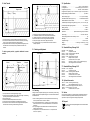
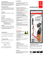
1. To find the driving axis, connect the datum and the aim point with a line.
2. Transfer the axis downwards into the construction ditch at two points along
this line. The two points should be as far apart as possible.
3. Adjust the laser beam on the first plumb by parallel traversing directly at the
laser beam and on the second plumb by a rotational movement in the
direction.
To achieve greater precision, a geodesic calibration is recommended.
Aim
rod
Zielstab
2
33. Checking and Adjustment
0001.500
0077.26
0062.01
0065.06
0026.06
0047.00
0031.00
0074.25
0094.00.1
36. Standard Delivery Package VL-80
Lattenstandpunkt
Rod location 1 1
3
Lattenstandpunkt
Rod location 2 2
A
B
Dreifuß base
Levelling
Levelling
Dreifuß base
5
Power supply: . . . . . . . . . . . . . . . . . . . . . . . . . . . . . . . . . 10 to 13.8 V DC/ 0.4 A
Reverse voltage protection and low battery cut-out: . . . . . . . . . . . . . . . . . . . yes
Watertight: . . . . . . . . . . . . . . . . . . . . . . . . . . . . . . . . . . . . . . . . . . . . . . 0.35 bar
Temperature range:. . . . . . . . . . . . . . . . . . . . . . . . . . . . . . . . . - 20° C to + 50° C
Weight: . . . . . . . . . . . . . . . . . . . . . . . . . . . VL-80 3.1 kg + PH-80 2.2 kg = 5.3 kg
Guarantee: . . . . . . . . . . . . . . . . . . . . . . . . . . . . . . . . . . . . . . . . . . . . . 12 months
Zielpunkt
Aim
point
Theodolit
Theodolite
4
7. Swap the aim rod for the theodolite and aim at the aim point.
8. The theodolite's plumb axis must correspond with the laser beam.
9. Transfer the axis into the construction ditch with the theodolite.
10. Set the laser beam in the axis using the directional adjustment.
11. Check point 8 again, correct errors, repeat points 9 and 10.
12. To increase accuracy, carry out measurement in the first and second
telescope positions.
Stativ
Tripod
a
b
M
6
VL-80
PH-80
FE-80
VF-80
Drifting laser
Transport case VL-80
Positioning device, suspended
Locking receiver
Drifting laser remote control
Battery connector, 2-pole C
Connection cable, 2.5 m, 2-pole C
Cable, 20 m, 3-pole C, VL-80 <> FE-80/VF-80 (2 pcs.)
5/8" hexagon bolt with nut and washer
37. Standard Delivery Package VL-70
0001.900 VL-70
0077.26
0062.01
PH-80
0047.00
0031.00
0094.00.1
Drifting laser
Transport case VL-80
Positioning device, suspended
Battery connector, 2-pole C
Connection cable, 2.5 m, 2-pole C
5/8" hexagon bolt with nut and washer
1
38. Optional Accessories
Target
beam
Zielstrahl
20 m
20 m
Richtige adjustment:
Justierung: AA--aa==BB- b
Correct
-b
34. Checking
1. Set up the laser at the correct height and align roughly.
2. Centre and level the theodolite over the measuring point (M). The measuring
point may also be behind the construction ditch.
3. Align on the aim point.
4. Transit the theodolite telescope and aim at the aim rod.
5. Push and fix the aim rod levelled with the levelling base into the axis.
6. Transfer the axis into the construction ditch using the theodolite and place
the laser beam in the axis by parallel traversing of the laser.
9
Although the laser is adjusted precisely by the manufacturer, jolts and strong
vibrations can lead to this adjustment being lost. The laser should therefore be
checked before use.
1. Select a measuring area that is as level as possible and around 40 m long
and set up the laser with the counter on "000.00".
2. Set up two measurement points - one directly in front of the laser and the
other around 40 m from it - and measure the distance on the centre of the
laser beam.
3. Set up a levelling instrument between the two measurement points and
measure both rod locations.
4. The adjustment is correct when the rod section A - a is equal to the rod
section B - b (sketch 1).
10
0071.01
PS-80 Positioning device, standing
0095.00.1
5/8" threaded spindle with 3 x hex nuts
0037.09
NE-12/2A Power supply with connection cable, 2 m
0048.01
EB-12/24 Energy box, 12 V/ 24 Ah
0031.36
Connection cable, 10 m, 2-pole
39. Service
Our devices are covered by a 12-month guarantee. Unauthorized opening of
the devices invalidates the guarantee. Please always send the laser in for
inspection or repair in its original case. Always specify the faults.
40. Disposal
The device must not be disposed together with the houshold rubbish
(electric scrap).
11