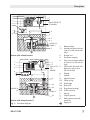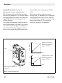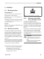
1
Electropneumatic Converters Type 6111 i/p Converter Type 6111 in standard version Type 6111 mounted on a supply air manifold Type 6111 in field enclosure Mounting and Operating Instructions EB 6111 EN Edition April 2015 Definition of signal words DANGER! Hazardous situations which, if not avoided, will result in death or serious injury WARNING! Hazardous situations which, if not avoided, could result in death or serious injury 2 NOTICE Property damage message or malfunction Note: Additional information Tip: Recommended action EB 6111 EN Contents 1 General safety instructions..............................................................................4 2 Description.....................................................................................................5 2.1 Application....................................................................................................5 2.2 Principle of operation......................................................................................5 2.3Versions.........................................................................................................6 3 Installation.....................................................................................................9 3.1 Mounting position...........................................................................................9 3.2 3.2.1 Electrical connection........................................................................................9 Mounting and installation in hazardous areas...................................................9 3.3 Pneumatic connection....................................................................................10 4 Operation....................................................................................................10 4.1 Checking zero and span................................................................................10 4.1.1Zero.............................................................................................................11 4.1.2Span............................................................................................................11 4.2 Zero adjustment for versions with an input signal of 0 to 20 mA.......................11 5 Maintenance................................................................................................12 6 Servicing explosion-protected devices...........................................................12 7 Supply air manifold for rail-mounting unit.....................................................13 7.1 Mounting the supply air manifold...................................................................13 7.2 7.2.1 7.2.2 7.2.3 Preparing the supply air manifold..................................................................13 Connectors...................................................................................................13 Fittings for pneumatic output signals...............................................................15 Connecting supply air manifolds....................................................................15 7.3 Mounting the Type 6111 Converter on the manifold........................................15 8 Troubleshooting...........................................................................................16 9 Technical data..............................................................................................17 10 Dimensions..................................................................................................19 11 Accessories..................................................................................................21 12 Article code..................................................................................................23 13 PTB certification............................................................................................25 EB 6111 EN 3 General safety instructions 1 General safety instructions −− The device must be mounted, started up or serviced by fully trained and qualified personnel only; the accepted industry codes and practices are to be observed. Make sure employees or third persons are not exposed to any danger. −− All safety instructions and warnings given in these mounting and operating instructions, particularly those concerning installation, start-up and maintenance, must be strictly observed. −− According to these mounting and operating instructions, trained personnel refers to individuals who are able to judge the work they are assigned to and recognize possible dangers due to their specialized training, their knowledge and experience as well as their knowledge of the applicable standards. −− The regulators comply with the requirements of the European Pressure Equipment Directive 2014/68/EU. Devices with a CE marking have a declaration of conformity, which includes information about the applied conformity assessment procedure. This declaration of conformity can be provided on request. −− To ensure appropriate use, only use the regulator in applications where the operating pressure and temperatures do not exceed the specifications used for sizing the regulator at the ordering stage. −− The manufacturer does not assume any responsibility for damage caused by external forces or any other external factors. −− Any hazards that could be caused in the valve by the process medium, operating pressure or by moving parts are to be prevented by taking appropriate precautions. −− Proper transport, storage, installation, operation and maintenance are assumed. 4 EB 6111 EN Description 2 Description 2.1 Application The device is used to convert a direct current input signal into a pneumatic output signal for measuring and control tasks. It is particularly suitable as an intermediate element between electric measuring devices and pneumatic controllers or between electric control devices and pneumatic control valves. The input is a load-independent direct current of 4 to 20 mA or 0 or 20 mA. The output is a pneumatic signal of 0.2 to 1 bar or other signal ranges up to max. 8 bar. 2.2 Principle of operation See Fig. 1 on page 7. The devices consist of an i/p converter module and a downstream volume booster. When operated, the supplied direct current i flows through the plunger coil (2) located in the field of a permanent magnet (3). At the balance beam (1), the force of the plunger coil, which is in proportion to the current, is balanced against the force of the dynamic backpressure pK, which is produced on the flapper (6) by the air jet leaving the nozzle (7). The supply air (9) flows to the bottom chamber of the volume booster (8) and a certain amount of air determined by the diaphragm position flows past the sleeve (8.5) and leaves through the output (OUTPUT 36). that the output signal is at least 100 mbar even at an input signal of 0 mA. As the input current and the forces acting on the plunger coil increase, the flapper (6) moves closer to the nozzle (7). This causes the backpressure pK upstream of the restriction (8.4) increase until it corresponds with the input current. The increasing backpressure pushes the diaphragm (8.3) and the plug sleeve (8.5) downwards. As a result, the supply air causes the output pressure pA to increase until a new state of equilibrium is reached in the diaphragm chambers. When the backpressure pK drops, the diaphragm moves upwards, releasing the plug sleeve. The output pressure pA can escape through the sleeve until the forces are equal again. Volume booster See Fig. 1 on page 7. Booster I (top diagram) II (bottom diagram) Output signal 0.1 bar or higher 0.0 bar or higher i/p converter module Type 6109 or Type 6112 Type 6112 only Note: A relatively stable supply air network is required for the version with volume booster II. The output signal pA is used also to supply the nozzle (7). The offset spring (8.2) ensures EB 6111 EN 5 Description Sample applications −− Booster I It can be used in all applications allowing a zero point of min. 0.1 bar. Jumps in the supply air network can be compensated for, without affecting the output signal. For example, to control pneumatic control valves. −− Booster II It can be used in applications requiring a zero point of 0 bar. For example, to control pneumatic cylinders or rollers used in the paper industry. 2.3 Versions See section 12 on page 23. 6 EB 6111 EN Description 1.1 1 6 7 2 Type 6109/6112 i/p Module 3 4 ZERO + – SPAN i pK 5 8.4 8 pA 8.2 8.3 OUTPUT 36 SUPPLY 9 8.5 Version with volume booster I 1 Balance beam 1.1 Mechanical zero point adjuster (0 to 20 mA version only) 2 Plunger coil 3 Permanent magnet 4 Zero point and span adjusters (not in 0 to 20 mA version) 5 Slide switch for switch-off electronics (not in 0 to 20 mA version) 6 Flapper 7 Nozzle 8 Volume booster 8.2 Offset spring 8.3 Diaphragm 8.4 Restriction 8.5 Plug sleeve (venting) 8.6 Fixed restriction 9 Springs pA Output pressure 6 2 7 Type 6112 i/p Module 3 4 i 1 ZERO + – SPAN pK 8 8.3 OUTPUT 36 pA 8.6 SUPPLY 8 8.5 Version with volume booster II Fig. 1: Functional diagram EB 6111 EN pK Backpressure (cascade pressure) Supply air 7 Description Switch-off electronics (see Fig. 2) Devices with an input range from 4 to 20 mA have a slide switch which activates the switch-off electronics. This function allows the input signal to be set to 0 mA when the signal falls below the switching point of 4.08 ± tolerance. This causes the pneumatic output to be vented to approximately 100 mbar. This guarantees, for example, the tight shut-off function of a valve. This function requires a characteristic which passes through the zero point, for example, at an output signal of 0.2 to 1 bar. If the characteristic line does not pass through zero, for example, for an allocated output signal from 0.8 to 2.7 bar, then the pneumatic output is vented to a remaining pressure of approx. 0.3 bar when the switch-off electronics are activated. 1.0 0.8 bar Output 0.2 to 1 bar Remaining pressure approx. 0.1 bar 0.6 Vent 0.4 0.2 4 3 8 12 16 20 bar mA Output 0.8 to 2.7 bar Remaining pressure approx. 0.3 bar 2.7 2 1 0.8 0.3 Slide switch for switch-off electronics 4 8 12 16 20 mA Fig. 2: Switch-off electronics 8 EB 6111 EN Installation 3 Installation 3.1 Mounting position Rail-mounting unit Snap the device onto the top-hat rail (see Rail-mounting unit on page 19). Optionally, mount it to a wall using the two Ø 5.5 mm holes. The devices can also be mounted to a supply air manifold using the corresponding accessories (see section 11). Field unit Mount it using the bracket (1400-7432). See Field unit on page 20. 3.2 Electrical connection For electrical installation, observe the relevant electrotechnical regulations and the accident prevention regulations that apply in the country of use. In Germany, these are the VDE regulations and the accident prevention regulations of the employers’ liability insurance. Adhere to the terminal assignment specified in the certificate. Switching the assignment of the electrical terminals may cause the explosion protection to become ineffective. +_ ZERO + _ SPAN 0/4 to 20 mA Fig. 3: Terminal connection · Input signal 3.2.1 Mounting and installation in hazardous areas The following regulations apply: EN 60079‑14 (VDE 0165‑1) Electrical Apparatus for Explosive Gas Atmospheres and EN 50281-1-2 (VDE 0165-2) Electrical Apparatus for Use in the Presence of Combustible Dust. The maximum permissible values specified in the EC type examination certificates apply when interconnecting intrinsically safe electrical equipment (Ui or U0, li or I0, Pi or P0, Ci or C0 and Li or L0). WARNING! Incorrect electrical connection will render the explosion protection unsafe. Adhere to the terminal assignment specified in the certificate. ÎÎ Connect the wires for the input signal to the (+) and (–) terminals. The terminals are designed for wires with 0.2 to 2.5 mm² (see section 9). No additional voltage supply is required. EB 6111 EN 9 Operation 3.3 Pneumatic connection 4 Operation Rail-mounting unit See Fig. 5 on page 19. The standard connections for supply air (SUPPLY 9) and output (OUTPUT 36) are designed as hose connections suitable for hose with 4 mm inside diameter and 6 mm outside diameter (see Rail-mounting unit on page 19). The hose connection are also available with 1/ 8 NPT, G 1/8 or M5 female thread. Field unit See Field unit on page 20. The pneumatic connections (supply air and output) are designed as a bore with ¼-18 NPT thread. Supply air (see section 9) −− Min. + 0.4 bar above the upper signal pressure range value −− Max. 10 bar Optional for rail-mounting unit: −− Supply over manifold (see section 7). 10 4.1 Checking zero and span The device converts the input signal proportionally into the output signal. The signal ranges are specified on the nameplate. The specified range is fixed and can only be changed by approx. 10 % using the potentiometers. If the device does not work properly for any reason, check the zero and span. The ZERO and SPAN potentiometers are accessible through the holes in the front cover after opening the clear plastic cover (see Fig. 1 and section 10). Note: The zero point of devices with booster I cannot be adjusted lower than 0.1 bar. Do not adjust the characteristic in devices with booster II at all as the setting is much more complicated than in the version with booster I. EB 6111 EN Operation 4.1.1 Zero 1. Connect a pressure gauge (minimum accuracy class 1) to the converter output. 2. Set the supply air to 0.4 bar above the upper output signal range value and apply it to the device. 3. Deactivate the switch-off electronics at the slide switch (5) (push the switch accessible through the oblong hole at the bottom of the converter away the ACTIVE arrow). 4. Set the input signal to the lower range value using a suitable ammeter (e.g. set it to 4 mA for 4 to 20 mA range = 0.2 to 1 bar). The output signal of the pressure gauge should now indicate 0.2 bar. If this is not the case, readjust the zero point accordingly with the ZERO potentiometer. 4.1.2 Span 2. If this is not the case, readjust the span accordingly with the SPAN potentiometer. 3. Change the input signal abruptly from 20 to 0 mA and check whether the output signal assumes the upper range value of 1.0 bar. As the adjustment of zero and span influence each other, recheck both values and correct them, if necessary. 4.2 Zero adjustment for versions with an input signal of 0 to 20 mA These versions do not have potentiometers to adjust zero or span nor switch-off electronics. The zero point can only be adjusted mechanically at the zero screw (1.1). To proceed, remove the front cover and insert a screwdriver through the hole in the cover of the Type 6112 i/p Module (see Fig. 1 and section 10). 1. Set the input signal to 20 mA (upper range value) using a suitable ammeter. For example, the output signal at the pressure gauge should now indicate 1.0 bar for a 4 to 20 mA range = 0.2 to 1.0 bar. EB 6111 EN 11 Maintenance 5 Maintenance No specific maintenance measures need to be carried out. To guarantee trouble-free operation of the converter, make sure that the supply air is always clean (see section 9 for air quality). Therefore, check the air filter and separator installed in the upstream air reducing station regularly. 6 Servicing explosion-protected devices If a part of the device on which the explosion protection is based needs to be serviced, the device must not be put back into operation until a qualified inspector has assessed it according to explosion protection requirements, has issued an inspection certificate or given the device a mark of conformity. Inspection by a qualified inspector is not required if SAMSON performs a routine test on the device before putting it back into operation. Document the passing of the routine test by attaching a mark of conformity to the device. Replace explosion-protected components only with original, routine-tested components from the manufacturer. Devices that have already been used outside hazardous areas and are intended for future use inside hazardous areas must comply with the safety requirements placed on serviced devices. Before being operated inside hazardous areas, test the devices according to the specifications for servicing explosion-protected devices. 12 EB 6111 EN Supply air manifold for rail-mounting unit 7 Supply air manifold for rail-mounting unit See Fig. 4 on page 14. Supply air manifolds and the corresponding accessories are listed in section 11. The manifold (Fig. 4) is available as an accessory and provides a common air supply for several Type 6111 i/p Converters. The manifold can be made to be as long as required by combining two or more connecting rails of the manifolds for 3, 4, 5 and 6 converters. Individual connecting rails are connected by a coupling (5, order no. 14007294) with seals (4). Optionally, the manifold can be fitted with a shut-off valve, pressure gauge as well as hose connections (screw or push-on fittings) for the output signals. 7.1 Mounting the supply air manifold To fix the manifold to a wall or to a panel in a control cabinet, drill holes for M5 screws in the groove of the connecting rail. Make sure you keep 18 mm distance between the holes and the left and right edge of the rail to allow you to mount the i/p converters properly. EB 6111 EN 7.2 Preparing the supply air manifold 7.2.1 Connectors Mount connectors (3 and 4) at the ends of the manifold rail and secure them in place with the grub screws (6). Supply air Connect the supply air either over the connector (3) or over a hose screw fitting or push-on fitting (10a or 10b). Firmly screw the hose screw fitting (10a) or push-on fitting (10b) with its seal (10.1) into one of the two connectors (3). If the accessories include a shut-off valve (11), mount it between the connector and supply air port screw fitting. End connection Screw screw plug (2) into the connector using sealing tape. If a pressure gauge (1) is fitted, seal it in place of the screw plug. Insert seals (4) on both connectors and push them on the left or right side into the connecting rail. Align connectors and secure them in place with the grub screws (6). 13 Supply air manifold for rail-mounting unit 1 Pressure gauge 2 Screw plugs 3 1) Connector G ¼ 4 1) Seals 5 Coupling 10 15 11 Connecting plate (hose connection) 16 1) Connecting plate (supply air manifold) with 3x10 mm screws Shut-off valve 11.1 Seal Connection for output signal a: Hose screw connection b: Hose push-on connection 7 7.1 Washer 8 1) Cap screw M4x16 9 1) O-ring 3x2.7 mm 1) 12 1) M3x6 screw with seal 10.1 Seal M4x6 grub screw 6 1) Connection for supply air (G ¼) a: Hose screw connection b: Hose push-on connection Included in the scope of delivery of the basic version 15 16 Holes for mounting 11 1 18 16 15 11.1 12 9 10a 3 4 10.1 10b 3 2 6 4 6 8 7a 5 4 7.1 4 7b Height of supply air manifold: 75 mm Fig. 4: Exchanging the connecting plate in the converter (top) · Assembling the supply air manifold (below) 14 EB 6111 EN Supply air manifold for rail-mounting unit 7.2.2 Fittings for pneumatic output signals Attach the output signal connection (7a or 7b) to the holes on the bottom of the connecting rail (G 1/8 thread). Fasten the hose screw fitting connection (7a) together with a washer (7.1). The hose push-on fitting connection (7b) has an integrated seal and is fastened without the washer (7.1). 7.2.3 Connecting supply air manifolds A coupling (5) with seals (4) is used to connect the individual connecting rails together: ÎÎ Place seals (4) on the outer grooves of the coupling (5). plate (16) using the two 3x10 mm screws included in the accessories (Fig. 4, top). ÎÎ Slightly tilt the converter upwards and place it on the manifold already mounted (7.1). Press the converter down and secure it with the fastening screw (8). Qty. Type 6111 ÎÎ Press the coupling into the manifold hole and push on the connecting rail as far as it will go. ÎÎ Screw in grub screws (6) to fasten the parts together. 7.3 Mounting the Type 6111 Converter on the manifold ÎÎ Attach fastening screws for Type 6111: Insert cap screws (8) from below into the holes in the connecting rail and push on O-rings (9) from the top to prevent the screws from falling out. 1) Note: If fewer Type 6111 Converters are mounted on the manifold than it is intended for, seal any unused holes in the supply air duct with the M3x6 cap screws (12) and seals included in the accessories. Combination with coupling Units per manifold rail 3 4 5 6 Manifold rail 1) length [mm] Height: 75 mm 3 1 – – – 108 4 – 1 – – 144 5 – – 1 – 180 6 – – – 1 216 7 1 1 – – 252 8 – 2 – – 288 9 – 1 1 – 324 10 – – 2 – 360 11 – – 1 1 369 12 – – – 2 432 13 1 – 2 – 468 14 – 1 2 – 504 15 – – 3 – 540 Plus length of accessories ÎÎ Unscrew the original connecting plate (15) from the bottom of the converter and replace it with the black connecting EB 6111 EN 15 Troubleshooting 8 Troubleshooting Problem Possible reasons Corrective action to be taken Comments Supply air not connect- Check supply air conneced tion. See section 3.3. No output signal deIncorrect terminal asspite changing the signment input signal Connect + and – terminals correctly. See section 3.2. NOTICE i/p converter does not need any extra voltage! Do not connect 24 V DC! Incorrect input signal Connect correct signal. Read nameplate: 0 to 20 mA or 4 to 20 mA. i/p converter constantly vents off air loudly i/p converter does not reach 100 % output e.g. 20 mA input: Output only 70 % instead of 100 % 16 Connections for supply Check pneumatic conair and output at the nections. See section i/p converter mixed up 3.3. Supply pressure too low. Supply air must be Read nameplate: 0.4 bar higher than the Output 0.2 to 1 bar → Supmax. output signal (supply air at least 1.4 bar ply air = 0.4 bar) Input signal faulty Check whether the input signal at the terminals reaches 100 % (100 % is e.g. 20 mA in standard version and 12 mA for split-range operation) NOTICE i/p converter has a load of: – max. 6 V (standard version) – max. 7 V (Ex ia version) Check specification concerning permissible load at the source of the input signal. EB 6111 EN Technical data 9 Technical data Type 6111 Explosion protection Input Load Standard Explosion-protected version without switch-off electronics with Type 6112 i/p Module Module A Module B Module C Module D Module E Module F Module G Module H Output Max. air output capacity 3) Supply air Air quality acc. to ISO 8573-1: 2001 Power consumption Characteristic Hysteresis Deviation from terminal-based conformity Effect in % of the upper range value Dynamic response Limiting frequency Phase shift Variable position 1) 2) 3) Rail-mounting unit Field unit II 2 G Ex ia IIC T6 II 3 G Ex nA IIC T6 4 to 20 mA (0 to 20 mA on request), for split-range: 4 to 12 mA or 12 to 20 mA, other signals on request ≤ 6 V (corresponding to 300 Ω at 20 mA) 7 V (corresponding to 350 Ω at 20 mA) ≤ 4 V (corresponding to 200 Ω at 20 mA) 0.2 to 1 bar (3 to 15 psi) (standard range) 0.4 to 2 bar (6 to 30 psi) (standard range) Special ranges adjustable at the factory to meet customer specifications Span ∆p Initial value 2) 0.1 to 0.4 bar 0.75 to 1.0 bar 0.1 to 0.4 bar 1.0 to 1.35 bar 0.1 to 0.4 bar 1.35 to 1.81 bar 0.1 to 0.8 bar 1.81 to 2.44 bar 0.1 to 0.8 bar 2.44 to 3.28 bar 0.1 to 0.8 bar 3.28 to 4.42 bar 0.1 to 1.2 bar 4.42 to 5.94 bar 0.1 to 1.2 bar 5.94 to 8.0 bar 1) 2.0 m³/h at an output of 0.6 bar (0.2 to 1.0 bar) 2.5 m³/h at an output of 1.2 bar (0.4 to 2.0 bar) 8.5 m³/h at an output of 5.0 bar (0.1 to 8.0 bar) At least 0.4 bar above the upper signal pressure range value, max. 10 bar without supply pressure regulator Max. particle size and density: Class 4 · Oil content: Class 3 · Pressure dew point: Class 3 or at least 10 K below the lowest ambient temperature to be expected 0.08 mn³/h at 1.4 bar · 0.1 mn³/h at 2.4 bar · Max. 0.26 mn³/h at 10 bar Characteristic: Output linear to input ≤0.3 % of final value ≤1 % of upper range value (for upper range values up to 5 bar); more exact values on request ≤1.5 % of upper range value (for upper range values above 5 bar) Supply air: <0.1 %/0.1 bar Alternating load, supply air failure, interruption of the input current: <0.3 % Ambient temperature: lower range value <0.03 %/K, span <0.03 %/K At an output of of 0.2 to 1 bar 5.3 Hz –130° Max. 3.5 % depending on mounting position: e.g. ± 1 % when mounted horizontally Initial value raised up to 3.0 bar (special version) The max. possible output pressure is 8 bar. Measured with 2 m hose with 4 mm inside diameter. EB 6111 EN 17 Technical data Technical data (continued) Ambient conditions, degree of protection, weight Storage temperature –40 to 70 °C Ambient temperature –20 to 70 °C Degree of protection Weight, approx. IP 20 IP 65 0.35 kg 1.9 kg Glass-fiber-reinforced polyamide Stainless steel 1.4581 Materials Housing 18 EB 6111 EN Dimensions 10Dimensions −− Rail-mounting unit Zero Adjuster Span Plastic cover Electric terminals 113 + _ 12 Top-hat rails ZERO SPAN 83 118 Label OUTPUT 36 SUPPLY 9 35 20 Pneumatic connections for hose with 4 mm inside diameter and 6 mm outside diameter Ø 5.5 mm holes for wall mounting 12 113 10 83 80 Version with connecting plate G 1/8 or 1/8 NPT thread 12.5 32.5 Fig. 5: Rail-mounting unit · Dimensions in mm EB 6111 EN Connecting plate 19 Dimensions −− Field unit Holes for attaching the bracket Cover 126 M6x1 Enclosure NPT 1/4 R 1/4 136 M20x1.5 76 69.5 Ø 30 Ø9 120 Bracket 1400-7432 Fig. 6: Field unit · Dimensions in mm 20 EB 6111 EN Accessories 11Accessories Item number in parentheses (x). See Fig. 4 on page 14. Accessories/spare parts · Connecting plate or adapter plate Order no. Connecting plate with hose connection (without coupling nut) (15) 0360-2950 M10x1 coupling nut for hose connection (15) 0250-1831 Connecting plate NPT (15) 0360-3251 1/8 Connecting plate G1/8 (15) 0360-3250 Adapter plate for supply air manifold (16) 0360-3096 3x12 mm screw for connecting plate with hose connection 8336-0728 3x16 mm screw for connecting plate (NPT and G) 8336-0730 3x10 mm screw for adapter plate for supply air manifold 8336-0727 Male screw fitting G 1/8 on hose with 4 mm inside diameter and 6 mm outside diameter, brass 8582-1450 Male screw fitting ¼ NPT on hose, 4 mm inside diameter and 6 mm outside diameter, brass 8582-1523 Accessories for field unit Order no. Mounting bracket (stainless steel) including two M6x12 hexagon head screws and washers to mount the field unit to the bracket Supply air manifold for converter units 3 1400-7432 4 5 6 Order no. Supply air manifold (basic version) including two G ¼ connectors 1400-... With one screw plug 7266 7273 7280 7287 With pressure gauge (0 to 6 bar) 7269 7276 7283 7290 With pressure gauge (0 to 6 bar) and shut-off valve 7270 7277 7284 7291 EB 6111 EN 21 Accessories Supply air manifold with hose screw fittings for outputs (hose with 4 mm inside diameter and 6 mm outside diameter) and supply air (hose with 8 mm inside diameter and 10 mm outside diameter) 1400-... With one screw plug 7267 7274 7281 7288 With pressure gauge (0 to 6 bar) and shut-off valve 7271 7278 7285 7292 Supply air manifold with hose screw fittings for outputs (hose with 4 mm inside diameter and 6 mm outside diameter) and supply air (hose with 8 mm inside diameter and 10 mm outside diameter) 1400-... With one screw plug 7268 7275 7282 7289 With pressure gauge (0 to 6 bar) and shut-off valve 7272 7279 7286 7293 Coupling (5) to connect supply air manifolds including two NBR seals (4) 1400-7294 Item number in parentheses (x). See Fig. 4. Accessories/spare parts · Supply air manifold Thread Pressure gauge, 0 to 6 bar (1) Connection for hose D/d Length [mm] mounted Order no. G ¼ A 27 8520-0019 Shut-off valve (11) G ¼ 30 8502-0044 Connector (3) G ¼ – 20 Connector G ¼ (3) – 0230-2581 Seal for connector (14x2.5 mm), NBR (4) 8421-0347 Hose screw fitting, output (7a) G 1/8 A D/d = 6/4 19 8582-1450 Hose push-on fitting, output (7b) G 1/8 A D/d = 6/4 13 8582-1563 G ¼ A D/d = 10/8 21 8582-1735 Washer (7.1) Hose screw fitting, supply air (10a) 8414-0136 Seal (10.1), hose connection Hose push-on fitting, supply air (10b) Connecting plate, standard (15) Connecting plate, supply air manifold (16) 8414-0140 G ¼ A D/d = 10/8 D 6 hose Attached to supply air manifold 23 8582-1564 0360-2950 0360-3096 Screw plug (2) 8323-0005 M4x6 grub screw (6) 8324-0605 M4x6 cap screw (8) 8333-0495 3x2.7 mm O-ring, NBR (9) 8421-0235 D = Outside diameter d = Inside diameter 22 EB 6111 EN Article code 12Article code Order no. Type 6111- x Without 0 1 II 2G Ex ia IIC T6 acc. to ATEX 8 II 3G Ex nA II T6 acc. to ATEX 4) Housing For rail mounting, 35 mm top-hat rail (DIN EN 60715) Field housing in stainless steel 1.4581 i/p module Type 6109 Type 6112 Input 4 to 20 mA with switch-off electronics 0 to 20 mA without switch-off electronics 1) 4 to 12 mA with switch-off electronics 12 to 20 mA with switch-off electronics Volume I (output from 0.1 bar/3 psi) II (output from 0 bar/0 psi) 2) booster Output 0.2 to 1.0 bar 3 to 15 psi 0.4 to 2.0 bar 6 to 30 psi Special Initial value 5) Span ∆p 0.1 to 0.4 bar 0.75 to 1.00 bar ranges 3) 0.1 to 0.4 bar 1.00 to 1.35 bar 0.1 to 0.4 bar 1.35 to 1.81 bar 0.1 to 0.8 bar 1.81 to 2.44 bar 0.1 to 0.8 bar 2.44 to 3.28 bar 0.1 to 0.8 bar 3.28 to 4.42 bar 0.1 to 1.2 bar 4.42 to 5.94 bar 0.1 to 1.2 bar 5.94 to 8.00 bar Operating Increasing/increasing Increasing/decreasing direction Pneumatic For hose with 4 mm inside and 6 mm connection outside diameter (screwed hose M10 x 1) 1/8 -27 NPT female thread ISO-228/G 1/8 female thread M5 female thread ¼-18 NPT Electrical For 0.5 to 2.5 mm² terminals connection Angle connector (DIN EN 175301-803) M20 x 1.5 Degree of IP 20 IP 65 protection Temperature Tmin ≥ –20 °C Spec. version Without x x x x 0 0 0 0 1 2 3 4 x x x 1 2 1 1 1 1 0 0 0 0 1 2 3 4 1 1 1 1 1 1 1 1 1 2 3 4 5 6 7 8 x x x x x x x x 0 0 0 Explosion protection 1) 2) 3) 4) 5) 0 1 1 2 2 2 2 2 2 2 2 2 2 2 2 2 2 2 2 1 2 0 0 0 0 0 1 0 0 1 0 1 1 2 3 4 1 2 3 1 2 0 Without switch-off electronics and without potentiometer for zero point and span correction A relatively stable supply air network is required for the version with volume booster II Specify setting range, e.g. set to 0.1 to 4 bar; output pressure max. 8 bar, supply air 10 bar For Ex nA version: rail-mounting unit in an enclosure with min. IP 54 (see statement of conformity, p. 26) Initial value raised up to 3.0 bar (special version 300 and 301) EB 6111 EN 23 24 EB 6111 EN Ptb14.doc Ptb14.doc EB 6111 EN Ptb14.doc Ptb14.doc 13PTB certification 25 26 EB 6111 EN Ptb 14 Ex n.doc Ptb 14 Ex n.doc EB 6111 EN 27 Ptb 14 Ex n.doc Physikalisch-Technische Bundesanstalt Weismüllerstraße 3 · 60314 Frankfurt am Main, Germany Phone: +49 69 4009-0 · Fax: +49 69 4009-1507 [email protected] · www.samson.de EB 6111 EN 2015-06-16 · English SAMSON AG · MESS- UND REGELTECHNIK