1
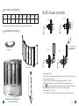
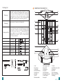
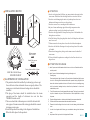
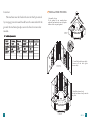
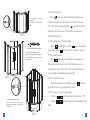
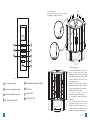
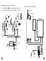
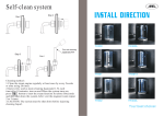
STEAM BATHROOM
MODEL : WS-701
Your best choice!
No advanced advice will be submit before we change our design and size.
The pictures may be a little different from the real products.
Our company keep the final explanation right.
TECHNIQUE PARAMETER
Vol tage
Ac 110 V( ±10%)
Water
Volatge
Freque ncy
60H Z
0.1~0 .2M pa
Power of
steam
generator
2.65K W
Power of
water pump
1.2H P
Power of
heat pump
1.0K W
Power of
air pump
Storage
capacity
Storage
capacity
0.2K W
66g al lon
0.3m
3
Self-clean system
Step 2
Step 1
CAUTIONS: Heat pump and air bubble pump is required by customers.
CONSTRUCTION SKETCH
Pour into cleaning
liquid from here
Handrail
Step 3
Step 4
Shower moveable rail
Glass door
01
SIZE1660x1660x2250 mm
65.4″x65.4″x88.6″
Cleaning method:
1.Clean the steam engine regularly at least once by every 2weeks
or after using 20 times.
2.Inject citric acid as main cleaning liquid,add 1.5L each
time.after 10 minutes, turn on and When the system turns on,
press
button to start the steam function for about 30seconds
and then shut down the system.After vent the stagnant
water,repeat 2 or 3 times.
3.CAUTION: The system must be shut down before injecting
WS-701 14
Packing list
Packing 1
Packing 2
Spare parts list
13
CONSTRUCTION SKETCH
four pieces of glass shower body, four pieces of fixed
glass door , two pieces of sliding glass door ,one piece of
post,two pieces of decorating post,two pieces of magnetic
strip,four pieces of water resist strip,six pieces of single
side plastic seal, two pieces of up and down bended
aluminum column,two pieces of decorating board.茎
one tray,one roof, two pieces of long handle.
two set of shower,one set of towel shelf,one piece of herb
box,one piece of soap box, one piece of drainage cover
,wheel with cover,two pieces of “T” shaped pillow,M6*25
screw(1),M6*35 screw(2),ST4*20 screw(3),ST4*25
screw(4),ST4*20 screw(5), ST4*12 screw(6),M4*25
screw(7),one instruction.
SCREW (1)
M6x25
10pcs
SCREW (2)
M6x35
10pcs
SCREW (3)
St4x20
4pcs
SCREW (4)
4pcs
SCREW (5)
St4x25
St4x20
SCREW (6)
St4x12
8pcs
SCREW (7)
M4x20
4pcs
1
2
11
12
3
13
4
5
6
14
15
16
17
18
7
19
8
16pcs
20
21
9
10
1.roof
2.top shower
3.room body
4.moveable shower
5.movable arm
6.handrail
7.nozzle
8.bottom bathtub
22
23
9.water pump switch
10.waterfall
11.exhaust fan
12.top light
13.decorated light
14.temperature needle
15.control panel
16.soap box
17.switch
18.cold/hot water switch
19.steam out
20.water in
21.air conditioning
22.big nozzle(6 PCS)
23.drainage
WS-701
02
ATTENTION
150 ″)
(5.9
The socket
of power and
the socket
of telephone
Cold water pipe
Hot water pipe
620(24.4″)
2250(88.6″)
INSTALLATION SKETCH
1800
(70.8″)
1250
(49.2″)
53
4″
)
29
″)
″)
0 (1
Other screws
5.
M4x16 M4x25
)
4″
1.
(6
29
1
0(
″)
60
60
.4
1 .4
0.9
16
16
5
(6
0(2
Install the screw
M6x25
1.In order to be tripped and fell down, pay more attention when get into the
steam room. Please don't shut the finger in the door in order to be hurt.
2.In order to avoid damaging the surface of products please do not use
hardness and sharpness tool to curve the products.
3.In order to course fire, no smoking inside the bathroom.
4.the jets of steam and drainage pipe both are high temperature when
products working, in order to be hurt please be careful.
5.In order to be tripped and fell down please keep clear of the bathtub after
taking shower each time.
6.It will be leaking if the glass glue plastic sheet be off then please add some
more for recover.
7.If there are marks of water please clear with soft cloth and toothpaste.
8.In order to be blocked of drainage device please keep clean of the surface
of bathtub.
9.Please do not hang up heavy things on the steam room or the handle of
steam room.
10.Please deal with the products according to the local laws when it is no
longer be use.
53
0(
ATTENTION FOR USAGE
20
.9
″)
Active chain wheel of glass
SIZE:1660×1660×2250mm
65.4″x65.4″x88.6″
ILLUSTRATION OF INSTALLATION
1.The products should be installed by technical guy who are got
the certificate or those technical who are assign by dealers. The
main power switch and electronic leakage device should be
installed.
2.The plug of electronic should be installed above the steam
generator and the length of electronic wire not less then
1800MM from the earth.
3.There are should be with main power switch for hot and cold
water pipe of steam room and the water pipe should be connect
to drainage water pipe.
4.Install the products according to the diagram of installation
When fixed the place for the products.
03
1、check if power and cold/hot water switch be turn on or be turn off each time before
use this product.
2、check if power of electronic leakage device be get through or not.
Checking way:
Press testing button, light of power be off, press button of restart then light of power
be on.It is not being what mentioned above after operated step by step,then that
shows the electronic protection device out off control or there is something wrong
with the electronic leakage device,so should ask professional to check and
maintain the product.
3、 Turn off the main power of control panel after stop usage. The plug of power should
be pull out because only turn off all the functions of control panel that is not stop
the power.
4、 People with hypertension or drunk are not allowed to have sauna steam bath.
5、 Children should have sauna steam bath under adult's instruction.
6、 Please don't shut the finger in the door in order to be hurt when get into the steam
room.
7、 In order to be tripped and fell down, pay more attention when get into the steam
room.
8、 keep clean of the tray in order to be tripped and fell down.
WS-701
12
Attention:
The machine must be fixed in the circuit which protected
by creepage protectionand should be well-connected with the
ground. Nontechnical people can not be fixed or removed at
random.
INSTALLATION PROCESS
1.Assembly of tray
If the ground is not smooth,please
adjust the nail under the tray to keep the
balance of the tray and ground.
STEP1
6、Technical parameter
Voltage
Current
KL-824
110V
Top light
20W
Sidelight
5W
25A
Fan
3.5W
AC12V
AC12V
DC12V
Power
2650W
protecting electrifying
I
Waterproof Grade
Gl
as
s
Ip4
Plastic
pad
Model
Water inlet valve Water drain valve
6W
DC12V
A
bo lumi
ard niu
m
7W
DC12V
S TEP2
2 Install the back shower body
Connect all the back glass
shower body.
3. Install the shower body
Put the back shower body onto the
tray,fix it.
11
S T E P3
WS-701 04
M4x1 2
4. Assembly of fixed
glass door
Connect the fixed glass
door.
STEP4
Active chain wheel of glass
5. Assembly of sliding door
put the sliding door into the up and
down aluminum track to keep it
balance,fix it.
STEP 5
M4x20
6. Install the shower body
Put the glass door on the tray,
together with the back shower
body,fix it.
(2) The application of the back lamp
Press
,the sidelight is on. Press
again, the ceiling
lamp is out, press
a third press, the sidelight is out too.
3) The steam function
Press
,startup the steam function, the water case
will pump water automati-cally. After 60minutes or so, it
will generate steam. (When the water case is lack ofwater,
the controller will replenish automatically)
(4) The air draft function
Under the condition of turnning on, press
can start
up air draft function, pressagain will colse it.
(5) The setting of time or temperature
1. Press
pitch can adjust the time from 1-99.
2. Press
pitch can adjust the temperature from
30-60 .
C
05
(1) The electrical pitch
Press
pitch can open the machine, the temperature
is the room temperature.The time will show 30m. At the same
time, it will open the ceiling lamp.Press again will close all the
functions. (After the closure of the machine, the water case
will drainfor 2 minutes)
C
STEP6
WS-701 10
7. Install the roof
Put the roof onto the top of shower
body,then fix tightly with bolts.
1
4
2
5
3
6
M4x20
7
8
C
STEP7
8. Install spare parts
A. Finish assembling the whole set,in
order to aviod water and steam
leaking,except the position of sliding
glass door do not use the silicone, the
silicone should be used on all else
connecting position .
B. While connecting the cold water
pipe and drain pipe ,wipe the silicone
on the connecting mouth to make it
will be connected very well.
C. Sketch map of pipe
connection(show as the picture).
D. Assembly of spare parts(shower
and so on)
A f e r a ll s p a r e p a r ts h a v e b e e n
installed well,put on the power
supply and cold/ hot water switch to
check whether all functions work
normally. If not,please install again.
C
1
Time adjustment pitch+
5
Temperature adjustment pitch-
2
Temperature adjustment pitch+
6
Fan Pitch
3
CeilingLamp/Back Lamp pitch
Steam Pitch
4
Time adjustment pitch-
7
8
M6x25
Main Cock Pitch
STEP8
09
WS-701
06
DRAWING OF WATER CONNECTION
As the“ ”
“ ”from the picture,please make the
connection according to the serial number v1,v2,etc.
ELECTRIC CIRCUIT SKETCH
clean system
Movable
shower head
steam outlet
Top shower
water inlet
Power
Switch
valve
Switch
valve
Waterfall
Movable
shower head
cold/hot
water
switch
Nozzle
cold/hot
water
switch
Hot water
connection
(red pipe)
Cold water
connection
(red pipe)
Steam
generator
clean system
Drainage
Steam out
water outlet
Nozzle
Control
panel
Light
(AC12V)
07
Fan
(DC12V)
WS-701
08