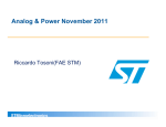
1
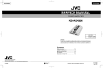
UM0933
User manual
STEVAL-ISW001V1 2.5 kW/135 A MMA welding machine
Introduction
The STEVAL- ISW001V1 is a 2.5 kW welding machine capable of 135 A of welding current.
It is designed for small industrial applications and domestic use in many DIY applications.
The machine is ready-to-use and designed to implement the Manual Metal Arc (MMA)
welding process and to weld iron and steel following MMA process recommendations.
The board is intended for demonstration purposes in order to evaluate the potential of silicon
devices on high power/current applications where the robustness/efficiency of the silicon
part is the key point for a reliable system.
The whole system is made up of two boards. A power board, where all the power devices
involved in the power conversion are fitted, and a small control board, which includes a
PWM generator and an analog control circuitry necessary to manage the MMA welding
process.
The design is:
Note:
■
Quick to set up and install
■
Re-usable (the Gerber files are available free)
■
Ready to downsize if required
Please read the safety and operating instructions section before attempting any operation
with this manual. Further technical and theoretical information on this board can be found in
the application note AN3200; 2.5 kW MMA welding machine.
Figure 1.
September 2010
Typical low-end welding machine topology
Doc ID 17386 Rev 1
1/16
www.st.com
www.BDTIC.com/ST
Contents
UM0933
Contents
1
Board description . . . . . . . . . . . . . . . . . . . . . . . . . . . . . . . . . . . . . . . . . . . 4
2
Safety and operating instructions . . . . . . . . . . . . . . . . . . . . . . . . . . . . . . 5
2.1
General . . . . . . . . . . . . . . . . . . . . . . . . . . . . . . . . . . . . . . . . . . . . . . . . . . . . 5
2.1.1
2.2
2.5 kW/135 A welding machine use . . . . . . . . . . . . . . . . . . . . . . . . . . . . . 5
2.5 kW/135 A welding machine installation . . . . . . . . . . . . . . . . . . . . . . . . 5
2.2.1
Electronic connection . . . . . . . . . . . . . . . . . . . . . . . . . . . . . . . . . . . . . . . . 6
2.2.2
2.5 kW/135 A welding machine demonstration setup . . . . . . . . . . . . . . . 6
2.3
Hardware layout . . . . . . . . . . . . . . . . . . . . . . . . . . . . . . . . . . . . . . . . . . . . . 7
2.4
Environmental and equipment considerations . . . . . . . . . . . . . . . . . . . . . . 8
2.5
2.5 kW/135 A welding machine board connection . . . . . . . . . . . . . . . . . . . 8
2.6
STEVAL-ISW001V1 main description . . . . . . . . . . . . . . . . . . . . . . . . . . . . 9
2.7
STEVAL-ISW001V1 circuital description . . . . . . . . . . . . . . . . . . . . . . . . . 10
2.8
IGBT or power MOSFET compatibility . . . . . . . . . . . . . . . . . . . . . . . . . . . 12
3
Schematics . . . . . . . . . . . . . . . . . . . . . . . . . . . . . . . . . . . . . . . . . . . . . . . 13
4
Revision history . . . . . . . . . . . . . . . . . . . . . . . . . . . . . . . . . . . . . . . . . . . 15
2/16
Doc ID 17386 Rev 1
www.BDTIC.com/ST
UM0933
List of figures
List of figures
Figure 1.
Figure 2.
Figure 3.
Figure 4.
Typical low-end welding machine topology . . . . . . . . . . . . . . . . . . . . . . . . . . . . . . . . . . . . . 1
2.5 kW/135 A welding machine STEVAL-ISW001V1 top view . . . . . . . . . . . . . . . . . . . . . . . 7
Power board schematic diagram . . . . . . . . . . . . . . . . . . . . . . . . . . . . . . . . . . . . . . . . . . . . 13
Control board schematic diagram . . . . . . . . . . . . . . . . . . . . . . . . . . . . . . . . . . . . . . . . . . . . 14
Doc ID 17386 Rev 1
www.BDTIC.com/ST
3/16
Board description
1
UM0933
Board description
This demonstration board represents a good starting point and a ready platform for a more
complete and dedicated system, even though it cannot be considered an industrial standard
welding machine and therefore is not for professional use. A particular method of
implementing welding current sensing is present on the board and patented. Thanks to the
cooperation of Magnetica, some magnetic components have been designed and optimized
for this application. All these components are orderable through Magnetica.
The layout of the power board has been optimized to have a low level of interference,
considering the power delivered and the current level present on many parts of the board.
Also the rectangular shape of the board and the position of the magnetic/silicon devices
were considered in order to guarantee a sufficient air flux on the parts which are more
involved in heat dissipation. An air fan is necessary for safe and reliable system use at all
times.
The board includes:
4/16
●
An input stage composed of a 25 A power rectifier bridge
●
An input filter stage necessary for compliance with EMC emission levels
●
A small analog control daughter board (operational-amplifier TSM102 and SG3525
PWM generator)
●
A power stage made up of a power IGBT or MOSFET and power ultrafast diodes.
●
A ferrite power high frequency transformer designed and manufactured for this
application
●
An output free air inductor with an auxiliary winding needed to implement the patented
output current sensing.
Doc ID 17386 Rev 1
www.BDTIC.com/ST
UM0933
Safety and operating instructions
2
Safety and operating instructions
2.1
General
During assembly and operation the 2.5 kW/135 A welding machine demonstration board
poses several inherent hazards including bare wires and hot surfaces. If the board or its
components are improperly used or installed incorrectly there is a danger of serious
personal injury and damage to property.
All operations involving transportation, installation, and use, as well as maintenance, are to
be carried out by skilled technical personnel (national accident prevention rules must be
observed). For the purposes of these basic safety instructions, “skilled technical personnel”
are considered to be suitably qualified people who are familiar with the installation, use, and
maintenance of power electronic systems.
Warning:
2.1.1
Many sources of serious danger are present on this board.
The board works directly from the mains and the input power
stage is not galvanic insulated. The ground of the
control/power system is not insulated from the mains and
could be a cause of electric shock, burns, or death. Hot
surfaces, capable of causing serious burns, are present on
the board. This board must be used only in a power
laboratory and only by engineers and technicians who are
experienced in power electronics technology and under the
proper protection. STMicroelectronics is not responsible for
the safety of the user or for any damage caused.
2.5 kW/135 A welding machine use
The 2.5 kW/135 A welding system is designed for demonstration purposes only and is not
intended for professional use, industrial manufacturing, or to be used as part of industrial
machinery. It is neither in production nor an industrial project. Conformity to safety rules and
standards needs to be monitored. The technical data, as well as information concerning the
supply conditions, must be taken from the correct documentation and strictly observed.
2.2
2.5 kW/135 A welding machine installation
The installation and cooling of the 2.5 kW/135 A welding machine is in accordance with the
specifications and the targeted application (see Section 2.2.2: 2.5 kW/135 A welding
machine demonstration setup).
●
Excessive strain on the board should be avoided. In particular, no components are to
be bent, or isolating distances altered, during transportation or handling
●
No contact should be made with electronic components and contacts
●
Do not put the heatsinks together in electric contact
●
The heatsinks are not electrically insulated from high voltage potential. There is a
danger of electric shock present.
Doc ID 17386 Rev 1
www.BDTIC.com/ST
5/16
Safety and operating instructions
UM0933
Electrical components must not be mechanically damaged or destroyed (in order to avoid
potential health risks).
2.2.1
Electronic connection
National accident prevention rules must be followed when working on the main power
supply with the power supply or power board in general.
The electrical installation is completed in accordance with the appropriate requirements
(e.g., cross-sectional areas of conductors, fusing, or PE connections; for further information
see Section 2.2.2).
2.2.2
2.5 kW/135 A welding machine demonstration setup
Special attention must be paid when setting a bench test to show the operation of the
2.5 kW/135 A welding machine.
This is a complete welding machine design, equipped with an analog welding logic control,
so also a real and practical welding process may be demonstrated.
●
Two options are available to startup the board.
–
working on a resistive dummy load
–
welding of real pieces of iron/steel
The first option (a resistive dummy load) is suggested if the user is not skilled in the welding
process. A suitable load is needed. Generally the plasma arc, responsible for metal arc
welding (in the case of iron or steel welding), can be modeled as follows (from the standard
regulation for MMA welding):
Varc = 20 + 0.04 × Iarc (representative of the peak voltage across the arc)
From this, assuming a welding current of 100 A is imposed, the output of the system is
about 24 V. The calculation of the equivalent resistive dummy load is:
Equation 1
R arc =
Varc
24
=
= 0 .24 Ω
Iarc
100
A resistor, capable of dissipating the maximum power delivered by the machine (2.5 kW), in
a range of resistance between 0.2 and 0.3 Ω, can be used. In this case a valid cooling
system (fan or water) should be used to diffuse the heat dissipated by the resistor.
For the second option, it is sufficient to connect a suitable clamp (available in most
specialized outlets, though not included in the demonstration package) to the negative
output of the board, through a cable not longer then 2 mt and with a cross section not less
than 16 mm2. Connect a suitable welding torch to the positive output, also using, in this
case, a cable with the same characteristics as for the negative connection. Once the clamp
is fixed to the iron sample, it is possible to start welding. A dedicated environment should be
considered for the demonstration. The demonstration must be carried out by persons skilled
in the arc welding process. The demonstration of a welding process can be dangerous to
the work environment or cause fire, due to the numerous incandescent sparks created by
the plasma arc. The work environment needs sufficient ventilation to assure the dispersion
of smoke caused by rod and metal fusion. Any person involved in the operation must wear
protective clothing, compliant with relevant accident prevention rules.
6/16
Doc ID 17386 Rev 1
www.BDTIC.com/ST
UM0933
Safety and operating instructions
In any case, avoid contact with metallic parts during welding and for some minutes after.
The welding process creates high temperatures to fuse the metal and therefore there is a
risk of serious burns.
Do not leave the rod unattended just after the welding operation. The tip of the rod remains
incandescent for some minutes and can be a cause of fire, damage to the environment, or
personal harm.
The welding process starts by putting the rod in contact with the metal sample connected to
the negative output through the clamp, supplied by the positive output of the board. Do not
directly touch the rod or the metal piece, the output voltage, at open load, can cause electric
shock.
An AC which is insulated and protected against overload and short-circuit is preferable to be
used during the evaluation test of the 2.5 kW/135 A welding machine.
In case of a resistive and dissipative dummy load, attention should be paid to the
temperature that the load could reach. The required equipment must be provided in order to
avoid hot surfaces and fire risk during the tests (fan, water cooled load, etc.).
Note:
Do not touch the board and its components after disconnection from the voltage supply, as
several parts and power terminals, which may contain energized capacitors, need to be
allowed to discharge.
2.3
Hardware layout
Figure 2.
2.5 kW/135 A welding machine STEVAL-ISW001V1 top view
The main input connector can be seen on the left-hand side in the image, near the fuse
connector. Connect a sinusoidal supply voltage with an amplitude in the range of between
185 VACrms to 265 VACrms or a DC voltage between 310 Vdc and 375 Vdc. The power
source must be able to supply the power required by the system, according to the welding
current required on the output. The two output connectors are present on the right-hand side
(close to the output free air inductor). On the centre of the board the ferrite high frequency
power transformer, made up of the double switch forward converter, can be found. The two
big heatsinks on the left-hand side are sized to allow power dissipation of the four power
Doc ID 17386 Rev 1
www.BDTIC.com/ST
7/16
Safety and operating instructions
UM0933
switches. The heatsink on the right-hand side allocates the output fast power diodes. In the
bottom end of the image, the control board, fitted by a strip connector, is visible. An external
potentiometer is present to set the welding current according to the metal pieces to be
welded. On the control board two small trimmers are present. Read the circuital description
in Section 2.7 carefully for information about the function and how to trim them. A trimmer is
present on the power board near the output inductor. Read the circuital description in
Section 2.7 carefully for information about the function and how to trim it.
Warning:
Note:
The STEVAL-ISW001V1 has no insulation shield or any other
type of protection case. The demonstration board must be
handled very carefully, as high potential (energy) parts are
exposed and may be touched. The user MUST avoid
connecting or removing cables during operation of the board,
or touching any part of the system when it is connected to
the main power supply.
After turning the power supply off, if the load is disconnected, the DC-link capacitor may still
hold a voltage.
It is preferable to test the kit in an ambient temperature not higher than 45 °C.
2.4
Environmental and equipment considerations
Read the recommendations in Section 2.2.2 carefully for environmental considerations.
Also, in the case of testing on a resistive dissipative dummy load, the STEVAL-ISW001V1
must only be used in a power laboratory equipped with a ventilation system or smoke
extractor fan system. The high voltage involved in the system presents a serious danger of
shock. If your purposes consist in measurement or waveform acquisition, or any other
interaction between the board and laboratory equipment, an AC insulated power supply
must be used.
Note:
Any measurement equipment must be isolated from the main power supply before powering
up the system. If using an oscilloscope with the kit, it is safer to isolate the AC supply AND
the oscilloscope, or use insulated differential probes. This prevents shock occurring as a
result of touching any SINGLE point in the circuit but does NOT prevent shock when
touching TWO or MORE points in the circuit.
An isolated AC power supply can be constructed using an isolation transformer and a
variable transformer (isolating the application rather than the oscilloscope is highly
recommended in any case).
2.5
2.5 kW/135 A welding machine board connection
The welding machine demonstration board comes ready-to-use and is made up of two
boards. A power board and a control board. The control board is a small daughter board
connected to the power board trough a strip-line connector. A small insulated auxiliary
power supply based on the VIPer16L is allocated to the power board. The auxiliary power
supply is used to generate all the low voltage supplies needed by the control board and the
gate driving section on the power board. In particular a +5 V, +15 V, and an insulated +15 V
8/16
Doc ID 17386 Rev 1
www.BDTIC.com/ST
UM0933
Safety and operating instructions
are generated. On the board there is a jumper marked “aux_supply_selection” that allows
the supply, through a separated external source, of the auxiliary power supply on the board.
When setting the jumper in position 1, the DC supply must be provided by an external DC
source capable of a minimum of 45 V (lower voltages do not assure the functioning of the
VIPer16 section) and a minimum current of at least 50 mA. When setting the jumper
aux_supply_selection to position 2, the DC source to the VIPer16 is directly the high voltage
bus available on the power board.
The possibility to use an independent voltage source, allows the control part to be tested or
to see some waveforms without supplying the power part. It can also be useful to supply the
power part with a lower voltage than the nominal in order to work in safe conditions.
Connect the board to the AC power supply (see Section 2.4 and Section 2.2.2).
Use a suitable cable, in terms of insulation and cross section, to be able to conduct the
current from the AC power supply according to the maximum power of the application.
Note:
The control system has a sensing of the output voltage delivered to identify a shortcut
condition during hot start or the welding phase. Supplying the power source with a limited or
out of nominal range voltage value can trigger this protection limiting the duty cycle. See the
circuit description (Section 2.7) to have information on how to disable this function. Supply
the welding machine board with a sinusoidal supply voltage with amplitude in the range
between 185 Vrms to 265 Vrms, or with a DC voltage between 310 Vdc and 375 Vdc. The
power source must be able to supply the power required by the system, according to the
welding current set.
Note:
Do not supply the system with a voltage value higher than 265 Vrms, there is a risk of
serious damage to the board and to property in this case. Do not supply the system with a
voltage below the minimum allowed, 185 Vrms, the system may not operate properly in this
condition.
Note:
A low voltage supply and maximum output load is the worst working condition for the
system, in this condition good cooling is mandatory.
2.6
STEVAL-ISW001V1 main description
The STEVAL-ISW001V1 demonstration board, developed by STMicroelectronics, provides
a ready-to-use demonstration solution for the implementation of an MMA welding machine.
The board can be used for demonstration purposes but is not, however, optimized for
industrial use or production machinery.
STMicroelectronics has patented a solution to improve the out-current control of the
machine without the use of a shunt resistor on the output. A simple analog circuit
reconstructs the current on the output using the input peak current on the primary side of the
insulation transformer as the input parameter and the reflected welding voltage on the
output inductor.
The current control also implements certain basic functions for good welding performance.
A hot start function improves the heating phase of the rod, during the initial contact with the
metal piece, which allows an immediate arc firing and a short-circuit time to be obtained.
Short-circuit protection drastically reduces the output current after 2 seconds, in case the
arc extinguishes and the consequent sticking of the welding rod. Thermal protection is also
Doc ID 17386 Rev 1
www.BDTIC.com/ST
9/16
Safety and operating instructions
UM0933
implemented using two ceramic thermostats, one mounted on the power switches heatsink
and one on the output power diodes heatsinks.
●
2.7
Features
–
Welding machine based on asymmetric forward double switch converter
–
Power stage based on IGBT or MOSFET
–
185 VACrms < VINACrms <265 VACrms
–
Lout max 135, regulated from 50 A
–
Auxiliary flyback power supply based on the VIPer16
–
L6386E gate driver
–
Analog control based on the TSM102 op amps + comparators
–
Output short-circuit protection
–
Hot start function
STEVAL-ISW001V1 circuital description
In Figure 3 the electronic schematic of the power board is shown.
Starting from the main supply input, a common mode filter and a power diode bridge can be
found. After the bridge, a DC bus, filtered by the electrolytic capacitor C35 and C36, is
available.
The auxiliary power supply, based on the VIPer16, is based on a flyback topology and can
supply two galvanic insulated low voltage supplies. One of these two low voltage sources is
connected to the common ground and used to supply all the logic and analog circuit present
on the control board, plus the gate driver. The insulated output (+15 V) is used to supply the
bootstrap section of the L6386 driver. In this way, a safe high side supply is assured.
The gate driver section is based on the L6386 chip. Using the internal comparator of the
L6386, also a hardware current protection has been implemented. The current, on the
primary side of the insulation transformer, measured by the current transformer on the
power board, after a partition through R48 and R49, is connected to pin 6. Pin 6 (Cin) is the
input of the internal comparator. If the voltage level on this pin rises to 0.5 V, the comparator
triggers, pulling down the DIAG pin. This pin is connected to the pin shutdown of the driver,
so a valid and fast current protection is implemented. In order to have a good current
capability and noise immunity on the gate of the power switches, the two outputs of the
driver (Hvg and Lvg) are buffered by two push-pulls. Two STS01DTP06s are used for this
purpose. The expected maximum peak current on the primary side is about 45 A at 135 A at
welding current. In these conditions two paralleled power switches are required. Two ultra
fast power diodes D25 and D32 are used to freewheel the magnetization current of the
transformer during the TOFF of the PWM. For this reason the maximum duty cycle cannot
surpass 50 % on this topology.
The power rectifier can be found on the secondary side of the power transformer made up of
ultra fast power diodes. An insulated sensing of the output voltage is implemented to identify
a short-circuit condition. In fact, during a normal arc condition a voltage between 18 and 25
V should be present on the output. The optocoupler senses the output voltage and gives
information to the control board. The trimmer R60 is useful to set a proper voltage threshold
to the optocoupler according to length and cross section of the cable used to connect the
board to the torch and clamp.
10/16
Doc ID 17386 Rev 1
www.BDTIC.com/ST
UM0933
Safety and operating instructions
In Figure 4 the electronic schematic of the control board is depicted.
●
Three basic blocks can be identified in the schematic of the welding machine control
board:
–
Analog amplification and computation block based on the TSM102
–
PWM generator based on the SG3525
–
Welding current dynamic reference based on discrete components
The analog amplification and computation block are based on the TSM102. This chip has
two operation amplifiers, two voltage comparators, and a voltage reference inside. The
operational amplifiers are used to implement an analog current control made up of a PID
and an integrator. The working principle is well described and explained in the application
note dedicated to the welding machine system (see AN3200; 2.5 kW MMA welding
machine).
One of the two amplifiers is used to implement the error amplifier for the current control. A
voltage representative of the output welding current is subtracted to a voltage level
representative of the wanted target current level. The error signal is amplified and
represents the PWM level to be set as the control variable to the power converter.
This is a standard PID control.
The measurement of the output current is obtained by an indirect estimation. By measuring
only the peak current on the primary side of the power insulation transformer, information on
the peak current at the output is obtained, following the relation between the primary and
secondary turn number on the windings.
To obtain information regarding the mean current on the load, information regarding the
current ripple on the output inductor is required. This information can be obtained by
acquiring the voltage reflected to the output inductor and integrating this information. (For a
more detailed explanation and mathematical model see the AN3200 application note
dedicated to the MMA welding machine. The last block is dedicated to giving the right target
to the current control, according to the MMA process status. In particular, two trimmers can
be found on the control board. The welding current setup trimmer and the short-circuit
current setup trimmer. The trimmer dedicated to setting the welding current is also
replicated on the power board in order to be free to solder three wires, and to position the
trimmer on the front panel of the welding machine for easy setting during the work.
The second trimmer, is dedicated to setting the maximum current wanted to force on the
output in case of a short-circuit condition.
Normally, in case of a short-circuit, the current is set to a higher value in order to fuse, as
soon as possible, the cause of the short-circuit, therefore avoiding the rod sticking to the
metal piece being welded. This behavior is totally automatic and dynamic, thanks to the
signal from the optocoupler previously mentioned. In the case of a short-circuit lasting for
more than 2 seconds, the circuit limits the current on the output to a small value, allowing
the operator to remove the rod and restart the plasma operation welding. This function can
be disabled if some laboratory tests must be carried out without taking into account the right
output voltage generated by the system. Connecting pins 15 or 16 of connector J12 to
ground the SC_Detection signal is also fixed to ground. In this condition it is simulating that
the voltage at the output of the welding machine is at the right level.
Warning:
In this case no kind of short-circuit protection or duty cycle
limitation is present.
Doc ID 17386 Rev 1
www.BDTIC.com/ST
11/16
Safety and operating instructions
2.8
UM0933
IGBT or power MOSFET compatibility
From laboratory tests and performance estimates on this application, the switches used on
the power section of the asymmetric forward converter can be IGBT or power MOSFET.
Only some small modifications to the value of the gate resistor must be carried out when
moving from IGBT to power MOSFET use. The demonstration board comes with an IGBT
STGW35HF60WD MDMeshTM II family device, and for this reason, on the electric
schematic, the graphic symbol is related to this kind of switch.
In terms of power MOSFET, the suggested part to be fitted to the application is the new
STW77N65M5 device.
12/16
Doc ID 17386 Rev 1
www.BDTIC.com/ST
Doc ID 17386 Rev 1
www.BDTIC.com/ST
!#IN
#/.
*
!
2
48
#OMMONMODECHOKEXM(
6
24
04#
24
04#
07-?).
3$
'.$
#URRENT?FEEDBACK
"53-ONITOR
6
#
U&8
*
&
#URRENT?FEEDBACK
07-?).
#
U&8
#
N&9
#
N&9
#
P&6
K
2
#
P&
*
%ARTH
24
.4#OHM
K
2
3$
K
2
6
#
#
N&6 .-
N&6
#
$
!6AC
2
2
'.$
#).
$)!'
6##
().
3$
,).
)#
'.$
,6'
.#
.#
/54
(6'
6"//4
,%$
V?)NSULATED
U&
6
#
#
U&
6
$
344(2
2
#
U&
6
#/-0
6DD
K
2
N&
2 N #
2 N #
1
# %
# "
# %
# "
# %
# "
# %
# "
343$40
#
U&0OLIESTERE
1
,)#
N&
2
K
KBREAK
'.$
2 2 2 2
2 2 $
3403
$
344(2
+ATODE?$
).
'.$
#
N6
2
OHMW
#
NV
2
OHMW
/54
5
,, !#:
*
0ROBLE?#URRENT
#
N&
#OLLECTOR?1
#
N&60OLIPROPILEN
$
344(,'
+ATODE?$
#
#
N&
U&6
#0#9,$,3
$
344(,'
1
34'7(&7$
N&60OLIPROPILEN
#
$
344(2
1
34'7(&7$
V?)NSULATED
#
U&6
#0#9,$,3
34'7(&7$
1
-AGNETICA
1
34'7(&7$
42!.3&/2-%2
#OLLECTOR?1
'.$
2
2 2
K
$2!).
6)0ER,
#/.42/,
&"
#
U&0OLIESTERE
343$40
6
#
N&
#
U&
#0#9,$,3
$
.
$
3403
$
48
#
Y
Y
Y
X
X
X
5
3&(
$ 3403#7
$
3403#7
#URRENT?FEEDBACK
$
344(
2
+7
"53-ONITOR
2
+7
2
+7
2
N&
!UX$#
344(
MAGNETICA
4!MAGNETICA
4
#
U&6
#0#9,$,3
6
6
#/.
2
!UX$#
2
K
#
+
2
V
$
27
27
#
N&6
2
27
2
K7
U(-AGNETICA
,
2
*
#
N&
344(
$
#
N&9
#
N&9
6?REFLECTEDFEEDBACK
2
$
27
3403#7
2
*
+7
+7
/UT?
*
/UT?
*
%!24(
*
Figure 3.
3
!UX?SUPPLY?SELECTION
UM0933
Schematics
Schematics
Power board schematic diagram
!-V
13/16
#
N&
$ $. 2
/54?7INDING?SENSE
4!?#URRENT
43
K
2
K
2
N&
#
6
K
2
K
2
2
K
# N&
K
2
K
2
K
2
43-
K
2
#
N&
2
K
K
2
OUT?COMP
INV?COMP
NONINV?COMP
6CC
NONINV?OP
INV?OP
OUT?OP
#ATHODE
3HUT?DOWN
OUT?COMP
INV?COMP
NONINV?COMP
6CC
NONINV?OP
INV?OP
OUT?OP
6REF
*
$ $.
2
-EG
2
K
6REF
#
6REF
6REF
K
2
U&6
2
K
6
Doc ID 17386 Rev 1
www.BDTIC.com/ST
2
K
+
2
K
N&
#
2
K
2
K
#
P&
2
K
2
K
"#
3'
K
2
6
K
2
6REF
6CC
SYNC
OUTB
OSC?OUT
6C
#4
'.$
OUT!
24
$)3
3HUT?DOWN
3OFT?START
COMP
*
K
2
$
ZENERV
6
1
"#
1
2 K
3%4
$
$.
2
K
2
#
N
2
$ $.
6
2 -EG
2
K
$
$.
# N&
2 K
14/16
#
N&
2
K
3$
2
K
$
$.
6
#
N&
07-?/54
#
P&
2
K
K
2
2
K
43
2
3$
3HUT?DOWN
6
6
3#?$ETECTION
07-?/54
/54?7INDING?SENSE
6
4!?#URRENT
"53-ONITOR
#
P
#/.
*
Figure 4.
3#?DETECTION
Schematics
UM0933
Control board schematic diagram
!-V
UM0933
4
Revision history
Revision history
Table 1.
Document revision history
Date
Revision
07-Sep-2010
1
Changes
Initial release.
Doc ID 17386 Rev 1
www.BDTIC.com/ST
15/16
UM0933
Please Read Carefully:
Information in this document is provided solely in connection with ST products. STMicroelectronics NV and its subsidiaries (“ST”) reserve the
right to make changes, corrections, modifications or improvements, to this document, and the products and services described herein at any
time, without notice.
All ST products are sold pursuant to ST’s terms and conditions of sale.
Purchasers are solely responsible for the choice, selection and use of the ST products and services described herein, and ST assumes no
liability whatsoever relating to the choice, selection or use of the ST products and services described herein.
No license, express or implied, by estoppel or otherwise, to any intellectual property rights is granted under this document. If any part of this
document refers to any third party products or services it shall not be deemed a license grant by ST for the use of such third party products
or services, or any intellectual property contained therein or considered as a warranty covering the use in any manner whatsoever of such
third party products or services or any intellectual property contained therein.
UNLESS OTHERWISE SET FORTH IN ST’S TERMS AND CONDITIONS OF SALE ST DISCLAIMS ANY EXPRESS OR IMPLIED
WARRANTY WITH RESPECT TO THE USE AND/OR SALE OF ST PRODUCTS INCLUDING WITHOUT LIMITATION IMPLIED
WARRANTIES OF MERCHANTABILITY, FITNESS FOR A PARTICULAR PURPOSE (AND THEIR EQUIVALENTS UNDER THE LAWS
OF ANY JURISDICTION), OR INFRINGEMENT OF ANY PATENT, COPYRIGHT OR OTHER INTELLECTUAL PROPERTY RIGHT.
UNLESS EXPRESSLY APPROVED IN WRITING BY AN AUTHORIZED ST REPRESENTATIVE, ST PRODUCTS ARE NOT
RECOMMENDED, AUTHORIZED OR WARRANTED FOR USE IN MILITARY, AIR CRAFT, SPACE, LIFE SAVING, OR LIFE SUSTAINING
APPLICATIONS, NOR IN PRODUCTS OR SYSTEMS WHERE FAILURE OR MALFUNCTION MAY RESULT IN PERSONAL INJURY,
DEATH, OR SEVERE PROPERTY OR ENVIRONMENTAL DAMAGE. ST PRODUCTS WHICH ARE NOT SPECIFIED AS "AUTOMOTIVE
GRADE" MAY ONLY BE USED IN AUTOMOTIVE APPLICATIONS AT USER’S OWN RISK.
Resale of ST products with provisions different from the statements and/or technical features set forth in this document shall immediately void
any warranty granted by ST for the ST product or service described herein and shall not create or extend in any manner whatsoever, any
liability of ST.
ST and the ST logo are trademarks or registered trademarks of ST in various countries.
Information in this document supersedes and replaces all information previously supplied.
The ST logo is a registered trademark of STMicroelectronics. All other names are the property of their respective owners.
© 2010 STMicroelectronics - All rights reserved
STMicroelectronics group of companies
Australia - Belgium - Brazil - Canada - China - Czech Republic - Finland - France - Germany - Hong Kong - India - Israel - Italy - Japan Malaysia - Malta - Morocco - Philippines - Singapore - Spain - Sweden - Switzerland - United Kingdom - United States of America
www.st.com
16/16
Doc ID 17386 Rev 1
www.BDTIC.com/ST