1
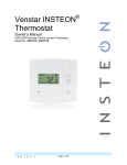
FanLinc™
INSTEON® Remote Control Light & Fan Controller
(Dual-Band)
Owners Manual (#2475F)
Page 1 of 12
2475F - Rev: 2/20/2014 8:33 AM
About FanLinc ............................................................................................................................................. 3
Features & Benefits .................................................................................................................................... 3
What’s in the Box? ..................................................................................................................................... 3
Installation ................................................................................................................................................... 4
Identifying the Electrical Wires in your Home ............................................................................................ 4
INSTEON Scenes ......................................................................................................................................... 5
Make Fan an INSTEON Responder .......................................................................................................... 5
Make Light an INSTEON Responder ........................................................................................................ 5
Remove FanLinc from a Scene as a Responder ...................................................................................... 6
LED and Beeper Behavior .......................................................................................................................... 6
LEDs .......................................................................................................................................................... 6
Beeper ....................................................................................................................................................... 7
Advanced Features ..................................................................................................................................... 7
Software Only Settings .............................................................................................................................. 7
Using FanLinc as a Phase Bridge ............................................................................................................. 7
Add an X10 Address .................................................................................................................................. 8
Factory Reset ............................................................................................................................................ 8
Specifications .............................................................................................................................................. 8
Troubleshooting ........................................................................................................................................ 10
Certification and Warranty ....................................................................................................................... 11
Certification .............................................................................................................................................. 11
FCC & Industry Canada Compliance Statement ..................................................................................... 11
Limited Warranty ..................................................................................................................................... 11
Limitations................................................................................................................................................ 12
Page 2 of 12
2475F - Rev: 2/20/2014 8:33 AM
About FanLinc
FanLinc is designed to easily incorporate both fan speed and light control within your INSTEON network.
It is a dual-load responder simultaneously acting as a light fixture dimmer plus a 4 speed fan controller
(off, low, medium & high).
Control from any INSTEON controller such as KeypadLinc, Mini Remote / RemoteLinc 2 and software.
Lights (blue)
Fan (red)
Line (black)
Fan
status
LED
Neutral (white)
Set button Set button Light
(lights)
(fan)
status
LED
Features & Benefits
•
•
•
•
•
•
•
•
4 Speed fan controller (off, low, medium & high)
300 Watt Incandescent Dimmer
X10 Compatible (1 address for light, 1 address for fan)
Dual-band repeater and access point
Designed to fit inside most ceiling fan cowlings
Dual set buttons & LEDs and a beeper for simple setup
All settings retained through power outages
2 year Warranty
What’s in the Box?
•
•
•
•
FanLinc
Wire nuts
1 cable tie
Quick-Start Guide
Page 3 of 12
2475F - Rev: 2/20/2014 8:33 AM
Installation
CAUTIONS AND WARNINGS
Read and understand these instructions before installing and retain them for future reference.
FOR CEILING FANS ONLY
FanLinc is intended for installation in accordance with the National Electric Code and local regulations in the United States or the
Canadian Electrical Code and local regulations in Canada. Use indoors only. FanLinc is not designed nor approved for use on
power lines other than 120VAC, 50Hz / 60Hz, single phase. Attempting to use FanLinc on non-approved power lines may have
hazardous consequences.
Recommended installation practices:
•
Use only indoors or in an outdoor rated box
•
Be sure that you have turned off the circuit breaker or removed the fuse for the circuit you are installing FanLinc in.
Installing FanLinc with the power on will expose you to dangerous voltages.
•
Connect only copper or copper-clad wire to FanLinc
•
FanLinc may feel warm during operation. The amount of heat generated is within approved limits and poses no
hazards. To minimize heat buildup, ensure that the area surrounding the FanLinc air vents is as clear of clutter as
possible.
•
To reduce the risk of overheating and possible damage to other equipment, use FanLinc load output to control no more
than 300 watts of 120VAC incandescent lamps plus no more than 1 Amp of Fan load. Dimming an inductive load (by
connecting to the light load wire), such as a fan or transformer, could cause damage to the dimmer, the load bearing
device, or both. If the manufacturer of the load device does not recommend dimming, use a non-dimming INSTEON
on/off switch. USER ASSUMES ALL RISKS ASSOCIATED WITH DIMMING AN INDUCTIVE LOAD.
•
You will need a flathead screwdriver, a Phillips head screwdriver and a voltage meter to install FanLinc
Identifying the Electrical Wires in your Home
To install FanLinc, you will need to identify the following four wires:
•
Line - usually black, may also be called HOT or LIVE, carries 120VAC electricity into the electrical box
•
Neutral - usually white commonly daisy chained from box to box usually appearing as a white wire bundle
•
Load – usually black, blue or red
•
Ground - Bare copper wire or metal fixture (if grounded)
If you are having difficulties identifying wires, consult an electrician to help you.
IMPORTANT!
•
If you have any difficulties or questions, consult an electrician. If you are not knowledgeable about, and
comfortable with electrical circuitry, you should have a qualified electrician install the product for you.
1) Write down the INSTEON ID (e.g., 12.34.56) for reference
2) Using your ceiling fan pull chains, set fan to highest speed and
turn light on (note: once installed, FanLinc will control all fan and
light functions)
3) Turn off the breaker (remove fuse) supplying power to the fan
4) Remove the ceiling fan from the electrical box
5) Identify line, neutral and load lines for fan and light separately
6) Disconnect wires from the ceiling fan (and light if applicable)
7) Connect FanLinc white wire and the fixture neutral wire to the
house neutral with wire nut
8) Connect FanLinc red wire to the fixture fan wire with a wire nut
9) Connect FanLinc blue wire to the fixture light wire (if fixture does
not have a light, cap the blue wire)
10) Connect FanLinc black wire to line with a wire nut
11) Ensure all connections are secure with no exposed copper
12) Turn breaker back on
FanLinc light LED turns green
FanLinc fan LED turns red
Page 4 of 12
2475F - Rev: 2/20/2014 8:33 AM
i. Optional: test by tapping set button a few times
Light will toggle between green (on) and red (off)
ii. Optional: cover LEDs with black electrical tape to avoid unwanted LED glow at night
which may be visible with some fan cowlings
13) While software is highly recommended to manage this hidden device, if you wish to set up any
scenes in FanLinc using the set buttons, it is critical that you do so now. See “INSTEON scenes”
14) Carefully remount cowling with FanLinc inside (or in electrical box). Use cable tie (included) to secure
FanLinc to fan bracket. Align cable tie with the notch on the FanLinc case ensuring that cable tie and
wires will not interfere with any moving parts.
INSTEON Setup
INSTEON remote control is done using scenes. Scenes allow you to instantly “recall” favorite lighting and
appliance settings at the touch of a button (or in response to central control or even a sensor). Each
scene has at least one controller and at least one responder. Simple scenes can be setup using the
instructions below.
Make Fan an INSTEON Responder
Follow the steps below to add your ceiling fan to an INSTEON scene.
1) Tap FanLinc Fan set button until FanLinc beeper & LED indicate the desired fan speed
FanLinc fan LED will be in the desired state (see table below)
Tap
Fan Speed
Beeper
LED
st
low
Single beep
Blinks Green Slow
nd
medium
Double beep
Blinks Green medium
rd
high
Fast Double beep
Blinks Green Fast
th
off
None
red
1
2
3
4
1
2) Press & hold the scene controller set button until it beeps
Controller LED will start blinking
3) Press & hold FanLinc fan set button until FanLinc double-beeps
FanLinc will (beep)-(beep) and the LED will return to previous state
1
Controller will (beep)-(beep) and its LED will stop blinking
4) If you wish to add your fan to more scenes, simply repeat these steps
5) Temporarily hang the fan from the mounting ring so the fan can spin safely and without obstruction.
Then while safely clear of the fan blades confirm the scene addition was successful by pressing on /
off on your scene controller
FanLinc fan LED will toggle between green and red
Make Light an INSTEON Responder
Follow the steps below to add your ceiling fan light to an INSTEON scene
2
1) Press & hold the scene controller button until it beeps
Controller LED will blink
2) Tap FanLinc light set button until the ceiling fan light is on
FanLinc light LED will be green
3) Press & hold FanLinc light set button until FanLinc double-beeps
1
2
Most models
If the controller does not have a beeper, wait until its LED begins blinking
Page 5 of 12
2475F - Rev: 2/20/2014 8:33 AM
FanLinc light LED will flash once & return to green
Controller will (beep)-(beep) and its LED will stop blinking
4) Confirm the scene addition was successful by tapping on / off on your scene controller
Ceiling fan light will toggle between on and off
5) If you wish to adjust the light’s scene on-level and/or ramp rate:
Adjusting on-Level:
a. Using your scene controller, adjust the ceiling fan light brightness to the desired
brightness for your scene
b. Repeat Steps #1 and #3 above
Adjusting Ramp Rate:
a. Using your scene controller, adjust the light brightness to correspond with the Ramp Rate
desired (Brighter = Faster, Dimmer = Slower)
b. Double-tap FanLinc light set button
c. Repeat Steps #1 and #3 above
6) If you wish to add FanLinc light to more scenes, simply repeat these steps
Remove FanLinc from a Scene as a Responder
Software is recommended.
Note: If you choose to remove FanLinc from use, it is important that you remove scene memberships
from all controllers. Otherwise, controllers will retry commands repetitively, creating network delays.
Follow the instructions below for each scene controller that FanLinc is a member of.
If you have both fan and light links, removing one will also remove the other. If you’d like to continue using
the other link, you’ll need to re-create it.
For simplicity sake, the steps below do not cover the removal or re-installation of the ceiling fan.
1) Use pull chain to turn fan motor off
2) Tap controller scene button
1
3) Press & hold controller set button until it beeps
Controller LED will start blinking
1
4) Press & hold controller set button until it beeps again
Controller LED will continue blinking
5) Press & hold fan (or light) set button until it double-beeps
Controller LED will stop blinking
6) Temporarily hang the fan from the mounting ring so the fan can spin safely and without obstruction
i. Move safely clear of the fan blades
7) Test by turning scene on and off from controller
LED and Beeper Behavior
LEDs
Fan LED
1
Green blink slow
Setup: set scene speed to slow
Green blink medium
Setup: set scene speed to medium
Green blink fast
Setup: set scene speed to fast
For devices without beepers hold until its LED begins blinking (this may take 10+ seconds)
Page 6 of 12
2475F - Rev: 2/20/2014 8:33 AM
Red on
Setup: set scene speed to off
Green on
Fan is on
Red on
Fan is off
Light LED
Blinking green
Setup: Awaiting X10 address
Blinking red
Setup: Awaiting X10 address removal
Green
Light is on
Red
Light is off
Beeper
Beeper
Single beep
Enter setup Mode (or transition to next setup Mode)
Double-beep
Setup successful, return to Ready Mode
3 Second beep
Fast beeps
Return to Ready Mode (either after setup time-out or userinitiated set button Tap)
on transition to next fan speed
Advanced Features
Software Only Settings
The following settings are available for programming only via compatible software (i.e. HouseLinc):
• Enable/Disable LEDs
• LED Blink on traffic
• Programming Lock
Using FanLinc as a Phase Bridge
FanLinc automatically bridges the electrical phases in your home (via communications with other dualband devices on the “other phase”). This is only important if you have powerline only INSTEON products
in your home. If you are relying on FanLinc to bridge the electrical phases, use the following procedure to
confirm bridging:
1) Tap FanLinc light set button four times quickly
FanLinc will start (beeping) once per second
FanLinc light LED will turn green
2) Check the LED behavior of other dual-band devices
•
If the “other” dual-band device is blinking green, it is on the other phase
Device provides a phase bridge to FanLinc
•
If the “other” dual-band device is blinking red, it is on the same phase
Device does not provide a phase bridge to FanLinc
Relocate if necessary (and practical)
•
If the “other” dual-band device is not blinking
Device not within RF range of FanLinc
Page 7 of 12
2475F - Rev: 2/20/2014 8:33 AM
3)
Does not provide a phase bridge to FanLinc
Relocate if necessary (and practical)
•
If the “other” dual-band device is exhibiting any other behavior or color, refer to its owners
manual
Tap FanLinc light set button
FanLinc will stop beeping
FanLinc light LED will turn red if light is off
Other device LEDs will stop blinking
Add an X10 Address
For the fan
1) Press & hold FanLinc fan set button until it beeps
FanLinc LED will start blinking green
2) Send the desired X10 address, plus on, 3 times (e.g. send B5, BON, B5, BON, B5, BON)
FanLinc will double-beep and the LED will stop blinking
3) Test by sending the X10 address on/off
FanLinc fan will turn on/off
For the light
1) Press & hold FanLinc light set button until it beeps
FanLinc LED will start blinking green
2) Send the desired X10 address, plus on, 3 times (e.g. send B5, BON, B5, BON, B5, BON)
FanLinc will double-beep and the LED will stop blinking
3) Test by sending the X10 address on/off
FanLinc light will turn on/off
For other X10 setup instructions visit http://www.smarthome.com/insteon-x10-programming.html
Factory Reset
NOTE: All settings and scenes will be erased
1) If possible, remove all links
2) Press & hold FanLinc light set button until it beeps
LED will start blinking green
3) Press & hold the FanLinc light set button until it beeps again
LED will start blinking red
4) The following three steps must be done quickly to the FanLinc light set button
a. Double-tap
b. Release
c. Press & hold
FanLinc will (beep), LEDs and light will turn off
FanLinc will ((((((beep)))))) for 5 seconds
5) Release after beeping stops
Light LED will turn green
Light LED will turn off
FanLinc will (beep)-(beep)
Light LED will turn green
Fan’s light will turn on
Specifications
General
Page 8 of 12
2475F - Rev: 2/20/2014 8:33 AM
Product Name
FanLinc – INSTEON In-line, Dual-load Module
Brand
Smarthome
Manufacturer Product Number
2475F
UPC
813922011548
FCC ID
SBP2475F
Warranty
2 Years, Limited
INSTEON
Maximum Links
400
Software Configurable
Yes, always a
RF Range
Up to 100’ Open Air
Beeper
Yes
X10
X10 Support
Yes
X10 Addresses
2 max, unassigned by default
Operation
Fan Controller
Light Dimmer
INSTEON
Group 2
INSTEON
Group 1
Fan speeds
4 (off, slow, medium &
fast)
Brightness levels
32
Fan responds to
on, off, fast on, fast off
and dim/brights + X10
commands
Dimmer responds to
on, off, fast on, fast off
and dim/brights + X10
commands
LED
Green = on
Red = off
Setup = varies
LED
Green = on
Red = off
Setup = varies
X10
1 Address, unassigned
by default
X10
1 Address, unassigned
by default
Brightness
Fan
Off
Off
1% - 49%
Slow
50% - 99% Medium
100%
Fast
Mechanical
Wires
Page 9 of 12
black – line
blue – light
red – fan
white – neutral
(all 16AWG)
2475F - Rev: 2/20/2014 8:33 AM
Case Color
White
Plastic
UV Stabilized ABS
Dimensions
114mm L x 50.8mm W x 22.2mm D
Weight
22g (0.05 lb)
Operating Environment
Indoors
Electrical
Retains all settings without power
Yes, all saved in Non-volatile EEPROM
Voltage
120VAC, Single Phase
Frequency
60Hz
Maximum Dimmer load
300 Watts
Maximum fan load
1 Amp
Safety Approved
ETL (Intertek Testing Services)
Certifications
FCC, IC Canada
Troubleshooting
Problem
FanLinc won’t add as a
Scene responder
Possible Cause
FanLinc may be out of range
Try moving an Access Point or installing other DualBand devices closer to FanLinc
The INSTEON signal may not be
getting to the “vicinity” of responder
Make sure phases are bridged, add additional
INSTEON devices and/or move around existing
INSTEON devices
Large appliances, such as refrigerators
or air conditioners, may be producing
electrical noise on the power line
Other electrical devices, such as
computers, televisions, or power strips,
may be absorbing the INSTEON signal
FanLinc will not turn on
light
FanLinc is taking a long
time to respond to scene
triggers
Page 10 of 12
Solution
Install a power line noise filter (e.g. #1626-10) to
filter electrical noise and minimize signal attenuation
Ramp Rate may be extremely slow
Add to scene again, with faster Ramp Rate
Pull chain on fan light is not in “ON”
position
Use pull chain to turn light on
Controller may be added to scene in off
Add to scene again, at desired brightness
state
Burned out bulbs
Change bulbs
Loose connection
Turn power off to fan assembly and recheck all
connections
Controller may be sending commands
to a another responder(s) that is no
longer in use
Remove all unused responders from the controller.
HINT: If you are using HouseLinc software, you can
easily check scene Membership and eliminate any
unnecessary
See Problem #1
If the above doesn’t work, perform a factory reset
on the controller
2475F - Rev: 2/20/2014 8:33 AM
Pull chain on fan is not set to HIGH
Use pull chain to set fan to highest speed setting
Scene speed was added on slow
Remove from scene and re-add at higher speed
The light dimming component inside
FanLinc “chops” the power line sine
wave to reduce the power.
The bulb filaments are vibrating. Use rough-service,
130 Volt, or appliance-grade bulbs to reduce the
noise.
Fan speed is too slow or
does not turn on
The light is buzzing when
on or dim.
Power cycle: Turn appropriate circuit breaker off,
wait 10 seconds and turn back on
FanLinc is no longer
responding.
Small electrical surge or voltage spike
Perform a factory reset on FanLinc and set up
scenes again
If you have tried these solutions, reviewed this Owner’s Manual, and still cannot resolve an issue you are
having with FanLinc, please call: 800-762-7845
Certification and Warranty
Certification
This product has been thoroughly tested by ITS ETL SEMKO, a nationally recognized independent third-party testing laboratory. The North American
ETL Listed mark signifies that the device has been tested to and has met the requirements of a widely recognized consensus of U.S. and Canadian
device safety standards, that the manufacturing site has been audited, and that the manufacturer has agreed to a program of quarterly factory followup inspections to verify continued conformance.
FCC & Industry Canada Compliance Statement
This device complies with FCC Rules Part 15 and Industry Canada RSS-210. Operation is subject to the following two conditions:
(1) This device may not cause harmful interference, and
(2) This device must accept any interference, including interference that may cause undesired operation of the device.
Le present appareil est conforme aux CNR d'Industrie Canada applicables aux appareils radio exempts de licence. L'exploitation est autorise aux deux
conditions suivantes:
(1) l'appareil ne doit pas produire de brouillage, et
(2) l'utilisateur de l'appareil doit accepter tout brouillage radiolectrique subi, mme si le brouillage est susceptible d'en compromettre le
fonctionnement.
The digital circuitry of this device has been tested and found to comply with the limits for a Class B digital device, pursuant to Part 15 of the FCC Rules.
These limits are designed to provide reasonable protection against harmful interference in residential installations. This equipment generates, uses,
and can radiate radio frequency energy and, if not installed and used in accordance with the instructions, may cause harmful interference to radio and
television reception. However, there is no guarantee that interference will not occur in a particular installation. If this device does cause such
interference, which can be verified by turning the device off and on, the user is encouraged to eliminate the interference by one or more of the following
measures:
- Re-orient or relocate the receiving antenna of the device experiencing the interference
- Increase the distance between this device and the receiver
- Connect the device to an AC outlet on a circuit different from the one that supplies power to the receiver
- Consult the dealer or an experienced radio/TV technician
WARNING: Changes or modifications to this device not expressly approved by the party responsible for compliance could void the user’s authority to
operate the equipment.
Limited Warranty
Seller warrants to the original consumer purchaser of this product that, for a period of two years from the date of purchase, this product will be free
from defects in material and workmanship and will perform in substantial conformity to the description of the product in this Owner’s Manual. This
warranty shall not apply to defects or errors caused by misuse or neglect. If the product is found to be defective in material or workmanship, or if the
product does not perform as warranted above during the warranty period, Seller will either repair it, replace it, or refund the purchase price, at its
option, upon receipt of the product at the address below, postage prepaid, with proof of the date of purchase and an explanation of the defect or error.
The repair, replacement, or refund that is provided for above shall be the full extent of Seller’s liability with respect to this product. For repair or
replacement during the warranty period, call support at 800-762-7845 with the Model # and Revision # of the device to receive an RMA# and send the
product, along with all other required materials to:
INSTEON
ATTN: Receiving
16542 Millikan Ave.
Irvine, CA 92606-5027
Page 11 of 12
2475F - Rev: 2/20/2014 8:33 AM
Limitations
The above warranty is in lieu of and Seller disclaims all other warranties, whether oral or written, express or implied, including any warranty or
merchantability or fitness for a particular purpose. Any implied warranty, including any warranty of merchantability or fitness for a particular purpose,
which may not be disclaimed or supplanted as provided above shall be limited to the two-year of the express warranty above. No other representation
or claim of any nature by any person shall be binding upon Seller or modify the terms of the above warranty and disclaimer.
Home automation devices have the risk of failure to operate, incorrect operation, or electrical or mechanical tampering. For optimal use, manually verify
the device state. Any home automation device should be viewed as a convenience, but not as a sole method for controlling your home.
In no event shall Seller be liable for special, incidental, consequential, or other damages resulting from possession or use of this device, including
without limitation damage to property and, to the extent permitted by law, personal injury, even if Seller knew or should have known of the possibility of
such damages. Some states do not allow limitations on how long an implied warranty lasts and/or the exclusion or limitation of damages, in which case
the above limitations and/or exclusions may not apply to you. You may also have other legal rights that may vary from state to state.
Protected under US and Foreign Patents (see www.insteon.com)
© Copyright 2012 Smarthome, 16542 Millikan Ave., Irvine, CA 92606, 800-762-7845, www.smarthome.com
Page 12 of 12
2475F - Rev: 2/20/2014 8:33 AM