1
Enterprise Fabric Suite 2007
User Guide
Sun Storage Fibre Channel Switch 5802
Firmware Version 7.4
Sun Microsystems, Inc.
www.sun.com
Part No. 820-4966-10
September 2008, Revision A
Submit comments about this document at: http://www.sun.com/hwdocs/feedback
Copyright 2008 Sun Microsystems, Inc., 4150 Network Circle, Santa Clara, California 95054, U.S.A. All rights reserved.
Sun Microsystems, Inc. has intellectual property rights relating to technology that is described in this document. In particular, and without
limitation, these intellectual property rights may include one or more of the U.S. patents listed at http://www.sun.com/patents and one or
more additional patents or pending patent applications in the U.S. and in other countries.
This document and the product to which it pertains are distributed under licenses restricting their use, copying, distribution, and
decompilation. No part of the product or of this document may be reproduced in any form by any means without prior written authorization of
Sun and its licensors, if any.
Third-party software, including font technology, is copyrighted and licensed from Sun suppliers.
QLogic, Enterprise Fabric Suite, SANdoctor, and QuickTools are trademarks or registered trademarks of QLogic Corporation.
Parts of the product may be derived from Berkeley BSD systems, licensed from the University of California. UNIX is a registered trademark in
the U.S. and in other countries, exclusively licensed through X/Open Company, Ltd.
Sun, Sun Microsystems, the Sun logo, Java, AnswerBook2, docs.sun.com, StorageTek, and Solaris are trademarks or registered trademarks of
Sun Microsystems, Inc., or its subsidiaries, in the U.S. and in other countries.
All SPARC trademarks are used under license and are trademarks or registered trademarks of SPARC International, Inc. in the U.S. and in other
countries. Products bearing SPARC trademarks are based upon an architecture developed by Sun Microsystems, Inc.
The OPEN LOOK and Sun™ Graphical User Interface was developed by Sun Microsystems, Inc. for its users and licensees. Sun acknowledges
the pioneering efforts of Xerox in researching and developing the concept of visual or graphical user interfaces for the computer industry. Sun
holds a non-exclusive license from Xerox to the Xerox Graphical User Interface, which license also covers Sun’s licensees who implement OPEN
LOOK GUIs and otherwise comply with Sun’s written license agreements.
U.S. Government Rights—Commercial use. Government users are subject to the Sun Microsystems, Inc. standard license agreement and
applicable provisions of the FAR and its supplements.
DOCUMENTATION IS PROVIDED "AS IS" AND ALL EXPRESS OR IMPLIED CONDITIONS, REPRESENTATIONS AND WARRANTIES,
INCLUDING ANY IMPLIED WARRANTY OF MERCHANTABILITY, FITNESS FOR A PARTICULAR PURPOSE OR NON-INFRINGEMENT,
ARE DISCLAIMED, EXCEPT TO THE EXTENT THAT SUCH DISCLAIMERS ARE HELD TO BE LEGALLY INVALID.
Copyright 2008 Sun Microsystems, Inc., 4150 Network Circle, Santa Clara, Californie 95054, États-Unis. Tous droits réservés.
Sun Microsystems, Inc. possède les droits de propriété intellectuels relatifs à la technologie décrite dans ce document. En particulier, et sans
limitation, ces droits de propriété intellectuels peuvent inclure un ou plusieurs des brevets américains listés sur le site
http://www.sun.com/patents, un ou les plusieurs brevets supplémentaires ainsi que les demandes de brevet en attente aux les États-Unis et
dans d’autres pays.
Ce document et le produit auquel il se rapporte sont protégés par un copyright et distribués sous licences, celles-ci en restreignent l’utilisation,
la copie, la distribution, et la décompilation. Aucune partie de ce produit ou document ne peut être reproduite sous aucune forme, par quelque
moyen que ce soit, sans l’autorisation préalable et écrite de Sun et de ses bailleurs de licence, s’il y en a.
Tout logiciel tiers, sa technologie relative aux polices de caractères, comprise, est protégé par un copyright et licencié par des fournisseurs de
Sun.
QLogic, Enterprise Fabric Suite, SANdoctor, et QuickTools sont des marques de fabrique ou des marques déposées de QLogic Corporation.
Des parties de ce produit peuvent dériver des systèmes Berkeley BSD licenciés par l’Université de Californie. UNIX est une marque déposée aux
États-Unis et dans d’autres pays, licenciée exclusivement par X/Open Company, Ltd.
Sun, Sun Microsystems, le logo Sun, Java, AnswerBook2, docs.sun.com, StorageTek, et Solaris sont des marques de fabrique ou des marques
déposées de Sun Microsystems, Inc., ou ses filiales, aux États-Unis et dans d’autres pays.
Toutes les marques SPARC sont utilisées sous licence et sont des marques de fabrique ou des marques déposées de SPARC International, Inc.
aux États-Unis et dans d’autres pays. Les produits portant les marques SPARC sont basés sur une architecture développée par Sun
Microsystems, Inc.
L’interface utilisateur graphique OPEN LOOK et Sun™ a été développée par Sun Microsystems, Inc. pour ses utilisateurs et licenciés. Sun
reconnaît les efforts de pionniers de Xerox dans la recherche et le développement du concept des interfaces utilisateur visuelles ou graphiques
pour l’industrie informatique. Sun détient une license non exclusive de Xerox sur l’interface utilisateur graphique Xerox, cette licence couvrant
également les licenciés de Sun implémentant les interfaces utilisateur graphiques OPEN LOOK et se conforment en outre aux licences écrites de
Sun.
LA DOCUMENTATION EST FOURNIE "EN L’ÉTAT" ET TOUTES AUTRES CONDITIONS, DÉCLARATIONS ET GARANTIES EXPRESSES
OU TACITES SONT FORMELLEMENT EXCLUES DANS LA LIMITE DE LA LOI APPLICABLE, Y COMPRIS NOTAMMENT TOUTE
GARANTIE IMPLICITE RELATIVE À LA QUALITÉ MARCHANDE, À L’APTITUDE À UNE UTILISATION PARTICULIÈRE OU À
L’ABSENCE DE CONTREFAÇON.
Please
Recycle
Contents
Preface
1.
xix
Using Enterprise Fabric Suite 2007
Workstation Requirements
1
1
Installing Enterprise Fabric Suite 2007
Starting Enterprise Fabric Suite 2007
Exiting Enterprise Fabric Suite 2007
2
3
6
Uninstalling Enterprise Fabric Suite 2007
8
Changing the Encryption Key for the Default Fabric View File
Saving and Opening Fabric View Files
9
Setting Enterprise Fabric Suite 2007 Preferences
Using Online Help
9
11
Viewing Software Version and Copyright Information
Enterprise Fabric Suite 2007 User Interface
Fabric Tree
12
12
15
Graphic Window
16
Data Window and Tabs
Menus
8
16
17
Topology Display Menu
17
Faceplate Display Menu
18
iii
Menu Shortcut Keys
Popup Menus
Tool Bar
20
21
22
Using the Topology Display
23
Working with Switches and Links
Selecting Switches and Links
24
24
Arranging Switches in the Topology Display
Topology Data Windows
25
Using the Faceplate Display
Alerts Panel
26
27
Port Views and Status
Working with Ports
Selecting Ports
28
29
29
Faceplate Data Windows
2.
Managing Fabrics
29
31
Tracking Fabric Firmware and Software Versions
Saving a Version Snapshot
32
Viewing and Comparing Version Snapshots
Exporting Version Snapshots to a File
Managing the Fabric Database
Adding a Fabric
33
33
Removing a Fabric
35
Opening a Fabric View File
Saving a Fabric View File
Rediscovering a Fabric
35
36
36
Deleting Switches and Links
36
Adding a New Switch to a Fabric
Replacing a Failed Switch
iv
31
37
Enterprise Fabric Suite 2007 User Guide • September 2008
36
32
32
25
Displaying Fabric Information
38
Link and Stack Link Data Windows
Devices Data Window
39
40
Displaying Fabric Status
41
Displaying the Event Browser
42
Filtering the Event Browser
Sorting the Event Browser
44
45
Saving the Event Browser to a File
Verifying Fibre Channel Connections
FC Ping Dialog
46
46
46
FC TraceRoute Dialog
47
Working with Device Information and Nicknames
Displaying Detailed Device Information
Exporting Device Information to a File
Managing Nicknames for Fabric Devices
Creating a Nickname
Editing a Nickname
Deleting a Nickname
52
Enabling In-band Management
53
Zones
Aliases
51
52
53
Zoning Concepts
50
51
Enabling SNMP Configuration
Managing Fabric Zoning
50
51
Importing a Nicknames File
3.
49
50
Exporting Nicknames to a File
Enabling Fabric Services
49
55
55
55
56
Zone Sets
56
Contents
v
Zoning Database
57
Active Zoneset Data Window
58
Configured Zonesets Data Window
Zoning a Fabric
59
60
Using the Zoning Wizard
61
Managing the Zoning Database
61
Editing the Zoning Database
Resolving Zoning
61
65
Configuring the Zoning Database
65
Saving the Zoning Database to a File
67
Restoring the Zoning Database from a File
Restoring the Default Zoning Database
Removing All Zoning Definitions
Managing Zone Sets
67
68
68
Creating a Zone Set
68
Activating and Deactivating a Zone Set
Renaming a Zone Set
70
Removing a Zone Set
70
Managing Zones
70
Creating a Zone in a Zone Set
71
Copying a Zone to a Zone Set
72
Adding Zone Members
Renaming a Zone
72
73
Removing a Zone Member
73
Removing a Zone from a Zone Set
74
Removing a Zone from All Zone Sets
Managing Aliases
74
Creating an Alias
vi
69
75
Enterprise Fabric Suite 2007 User Guide • September 2008
74
67
Adding a Member to an Alias
75
Removing an Alias from All Zones
Merging Fabrics and Zoning
Zone Merge Failure
76
76
Zone Merge Failure Recovery
4.
Managing Fabric Security
User Account Security
Port Security
77
79
Security Consistency Checklist
Connection Security
76
79
80
80
81
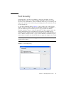
Configured Security Data Window
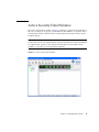
Active Security Data Window
Fabric Binding
Device Security
82
83
84
85
Managing Device Security
86
Using the Edit Security Dialog
Creating a Security Set
87
88
Create a Security Group Dialog
Creating a Security Group
89
89
Create a Security Group Member Dialog
90
Editing the Security Configuration on a Switch
92
Viewing Properties of a Security Set or Security Group
Using the Security Config Dialog
94
Archiving a Security Configuration to a File
Activating a Security Set
Deactivating a Security Set
Using RADIUS Servers
93
94
95
95
95
Adding a RADIUS Server
96
Contents
vii
Removing a RADIUS Server
99
Editing RADIUS Server Information
100
Modifying Authentication Order RADIUS Server Information
5.
Managing Switches
103
Managing User Accounts
104
Creating User Accounts
105
Removing a User Account
106
Changing a User Account Password
Modifying a User Account
108
Displaying Switch Information
108
Switch Data Window
109
Configuring Port Threshold Alarms
Paging a Switch
107
116
118
Setting the Date/Time and Enabling NTP Client
Resetting a Switch
120
Managing Switch Stacks
Configuring a Switch
121
122
Using the Configuration Wizard
Switch Properties
123
123
Domain ID and Domain ID Lock
Syslog
124
125
Symbolic Name
125
Switch Administrative States
Broadcast Support
125
126
In-band Management
126
Fabric Device Management Interface
Advanced Switch Properties
Timeout Values
viii
127
128
Enterprise Fabric Suite 2007 User Guide • September 2008
126
119
101
Managing System Services
Archiving a Switch
130
Restoring a Switch
131
Testing a Switch
128
133
Restoring the Factory Default Configuration
Configuring the Network
Network Properties
135
137
137
Network IP Configuration
138
Network DNS Configuration
Network IP Security
143
Security Policies
143
Security Associations
141
143
Create IP Security Association Dialog
Create IP Security Policy Dialog
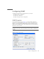
Configuring SNMP
147
149
SNMP Properties
149
SNMP Configuration
150
SNMP Trap Configuration
SNMP v3 Security
154
Installing Feature License Keys
Installing Firmware
150
151
Downloading a Support File
Using Call Home
145
154
155
157
Using the Call Home Profile Manager
Using the Call Home Profile Editor
160
161
Using the Call Home Profile Editor - Tech Support Center Profile Dialog
163
Applying All Profiles on a Switch to Other Switches
Using the Call Home Message Queue
165
166
Contents
ix
Testing Call Home Profiles
Change Over
6.
Managing Ports
166
167
169
Displaying Port Information
169
Port Statistics Data Window
169
Port Information Data Window
173
Digital Diagnostics Monitoring
176
Monitoring Port Status
179
Displaying Port Types
179
Displaying Port Operational States
Displaying Port Speeds
180
180
Displaying Transceiver Media Status
Configuring Ports
181
Changing Port Symbolic Name
182
Changing Port Administrative States
Changing Port Speeds
Changing Port Types
I/O Stream Guard
Device Scan
181
183
183
184
185
185
Auto Performance Tuning and AL Fairness
Using the Extended Credits Wizard
Resetting a Port
186
188
Moving a Licensed Port
Testing Ports
189
189
Graphing Port Performance
191
Starting Performance View
Exiting Performance View
192
193
Saving and Opening Performance View Files
x
185
Enterprise Fabric Suite 2007 User Guide • September 2008
194
Changing the Default Performance View File Encryption Key
Setting Performance View Preferences
Setting the Polling Frequency
Displaying Graphs
194
195
195
196
Arranging Graphs in the Display
Customizing Graphs
197
197
Setting Global Graph Type
199
Rescaling a Selected Graph
199
Saving Graph Statistics to a File
200
Contents
xi
xii
Enterprise Fabric Suite 2007 User Guide • September 2008
Figures
FIGURE 1-1
Enter CD Serial Number and License Key Dialog 4
FIGURE 1-2
Password Change Required Dialog 5
FIGURE 1-3
Initial Start Dialog 5
FIGURE 1-4
Enterprise Fabric Suite 2007 Window 6
FIGURE 1-5
Save Default Fabric View File Dialog 7
FIGURE 1-6
Load Default Fabric File Dialog 7
FIGURE 1-7
Preferences Dialog – Enterprise Fabric Suite 2007 11
FIGURE 1-8
Topology Display Elements 13
FIGURE 1-9
Faceplate Display
14
FIGURE 1-10
Backplate Display
14
FIGURE 1-11
Fabric Tree 15
FIGURE 1-12
Topology Display 24
FIGURE 1-13
Faceplate Display
FIGURE 1-14
Alerts Panel 28
FIGURE 2-1
Fabric Version Snapshot Analysis Dialog 33
FIGURE 2-2
Add a New Fabric Dialog 34
FIGURE 2-3
Link Data Window 39
FIGURE 2-4
Devices Data Window 40
FIGURE 2-5
Events Browser
FIGURE 2-6
Filter Events Dialog 45
27
43
xiii
FIGURE 2-7
FC Ping Dialog 47
FIGURE 2-8
FC TraceRoute Dialog 48
FIGURE 2-9
Detailed Devices Display Dialog 49
FIGURE 3-1
Active Zoneset Data Window 59
FIGURE 3-2
Configured Zonesets Data Window 60
FIGURE 3-3
Edit Zoning Dialog 62
FIGURE 3-4
Zoning Config Dialog 66
FIGURE 4-1
Port Binding Dialog 81
FIGURE 4-2
Configured Security Data Window 82
FIGURE 4-3
Active Security Data Window 83
FIGURE 4-4
Edit Security Dialog 87
FIGURE 4-5
Create Security Set Dialog
FIGURE 4-6
Create Security Group Dialog 89
FIGURE 4-7
Create a Security Group Member Dialog 90
FIGURE 4-8
Security Config Dialog 94
FIGURE 4-9
Add Server
FIGURE 4-10
Remove Server
FIGURE 4-11
Edit Radius Server Information 100
FIGURE 4-12
Modify Authentication Order - Radius Server Information 101
FIGURE 5-1
User Account Administration Dialog – Add Account 105
FIGURE 5-2
User Account Administration Dialog – Remove Account
FIGURE 5-3
User Account Administration Dialog – Change Password 107
FIGURE 5-4
User Account Administration Dialog – Modify Account 108
FIGURE 5-5
Switch Data Window 110
FIGURE 5-6
Switch Data Window Buttons
FIGURE 5-7
Port Threshold Alarm Configuration Dialog 117
FIGURE 5-8
Port Threshold Alarm Example 118
FIGURE 5-9
Switch Stacks
FIGURE 5-10
Switch Properties Dialog 124
FIGURE 5-11
Advanced Switch Properties Dialog 128
xiv
88
97
99
111
121
Enterprise Fabric Suite 2007 User Guide • September 2008
106
FIGURE 5-12
System Services Dialog 129
FIGURE 5-13
Restore Dialogs – Full and Selective 132
FIGURE 5-14
Switch Diagnostics Dialog 134
FIGURE 5-15
Network Properties Dialogs 138
FIGURE 5-16
IPsec Configuration Dialog 144
FIGURE 5-17
Create IP Security Association Dialog 145
FIGURE 5-18
Create IP Security Policy Dialog 147
FIGURE 5-19
SNMP Properties Dialog 149
FIGURE 5-20
SNMP v3 Manager Dialog 152
FIGURE 5-21
SNMP v3 User Editor Dialog 153
FIGURE 5-22
Features License Key Dialog 155
FIGURE 5-23
Add License Key Dialog 155
FIGURE 5-24
Load Firmware Dialog 157
FIGURE 5-25
Call Home Setup Dialog 158
FIGURE 5-26
Call Home Profile Manager Dialog 161
FIGURE 5-27
Call Home Profile Editor Dialog 162
FIGURE 5-28
Call Home Profile Editor - Tech Support Center Profile Dialog 163
FIGURE 5-29
Call Home Profile Multiple Switch Apply Dialog 165
FIGURE 5-30
Call Home Message Queue Dialog 166
FIGURE 5-31
Call Home Profile Manager Dialog 166
FIGURE 6-1
Faceplate Display — Port Statistics
FIGURE 6-2
Faceplate Display — Port Information 173
FIGURE 6-3
Port Information Data Window Buttons 174
FIGURE 6-4
DDM Entries and Information Button 177
FIGURE 6-5
Detailed Media Display Dialog 178
FIGURE 6-6
Port Properties Dialog 182
FIGURE 6-7
Advanced Port Properties Dialog 186
FIGURE 6-8
Designate Donor Ports
FIGURE 6-9
Move Port Dialog 189
FIGURE 6-10
Port Diagnostics Dialog 190
170
188
Figures
xv
FIGURE 6-11
Fabric View Graphs
FIGURE 6-12
Save Default Performance View File Dialog 193
FIGURE 6-13
Load Default Performance File Dialog 194
FIGURE 6-14
Preferences – Performance View 195
FIGURE 6-15
Set Graph Polling Frequency Dialog 196
FIGURE 6-16
Default Graph Options Dialog 198
xvi
192
Enterprise Fabric Suite 2007 User Guide • September 2008
Tables
TABLE 1-1
Workstation Requirements 2
TABLE 1-2
Topology Menu Options
17
TABLE 1-3
Faceplate Menu Options
18
TABLE 1-4
Tool Bar Buttons 22
TABLE 2-1
Devices Data Window Entries 41
TABLE 2-2
Topology Display Switch and Status Icons
TABLE 2-3
Severity Levels 44
TABLE 3-1
Edit Zoning Dialog Tool Bar Buttons and Icons
TABLE 5-1
Factory User Accounts 104
TABLE 5-2
Switch Data Window Entries
TABLE 5-3
Switch Resets
TABLE 5-4
Switch Administrative States 126
TABLE 5-5
Factory Default Configuration Settings
TABLE 5-6
Network Properties- IP Configuration 139
TABLE 5-7
Network Properties - DNS Configuration 141
TABLE 5-8
IPsec Configuration Dialog Buttons
TABLE 5-9
Create IP Security Association Dialog Fields
TABLE 5-10
Create IP Security Policy Dialog Fields
TABLE 5-11
SNMP Configuration Parameters
TABLE 5-12
SNMP Trap Configuration Parameters 151
42
63
111
120
135
144
146
147
150
xvii
TABLE 5-13
SNMP v3 User Editor Dialog 153
TABLE 5-14
Call Home Setup Entries
TABLE 5-15
Call Home Editor - Tech Support Center Profile Entries
TABLE 6-1
Port Statistics Data Window Entries 170
TABLE 6-2
Port Information Data Window Entries 174
TABLE 6-3
Port Types
TABLE 6-4
Port Operational States
TABLE 6-5
Port Speeds
TABLE 6-6
Transceiver Media View 181
TABLE 6-7
Port Administrative States
TABLE 6-8
Port Speeds
TABLE 6-9
Port Types
xviii
158
179
180
180
183
184
185
Enterprise Fabric Suite 2007 User Guide • September 2008
164
Preface
This guide describes the Enterprise Fabric Suite™ 2007 application for Sun FC
switches and directors. This guide introduces the switch management products and
explains their installation and use. It is intended for users responsible for installing
and using switch management tools.
How This Document Is Organized
The Enterprise Fabric Suite 2007 switch management application is the primary
focus of this manual which is organized as follows:
■
Chapter 1 describes how to use Enterprise Fabric Suite 2007, its menus, and its
displays.
■
Chapter 2 describes fabric management tasks.
■
Chapter 3 describes fabric zoning management tasks.
■
Chapter 4 describes fabric security management tasks.
■
Chapter 5 describes switch management tasks.
■
Chapter 6 describes port and device management tasks.
A glossary of terms and an index are also provided.
xix
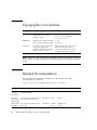
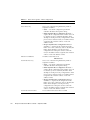
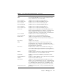
Typographic Conventions
Typeface
Meaning
Examples
AaBbCc123
The names of commands, files,
and directories; on-screen
computer output
Edit your.login file.
Use ls -a to list all files.
% You have mail.
AaBbCc123
What you type, when contrasted
with on-screen computer output
% su
Password:
AaBbCc123
Book titles, new words or terms,
words to be emphasized.
Replace command-line variables
with real names or values.
Read Chapter 6 in the User’s Guide.
These are called class options.
You must be superuser to do this.
To delete a file, type rm filename.
Note – Characters display differently depending on browser settings. If characters
do not display correctly, change the character encoding in your browser to Unicode
UTF-8.
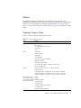
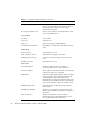
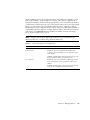
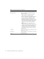
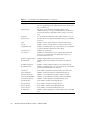
Related Documentation
The following table lists the documentation for this product. The online
documentation is available at:
http://docs.sun.com/app/docs/prod/switch.dir#hic
Application
Title
Part Number
Format
Location
Regulatory
and safety
information
Sun Storage Regulatory and Safety
Compliance Manual
820-5506-xx
PDF
Online
Hardware
and software
requirements
Sun Storage Fibre Channel Switch
5802 Hardware Release Notes
820-5539-xx
PDF
Online
Initial switch
installation
Sun Storage Fibre Channel Switch
5802 Setup
820-4950-xx
Printed
PDF
Shipping kit
Online
xx
Enterprise Fabric Suite 2007 User Guide • September 2008
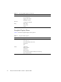
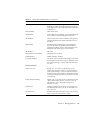
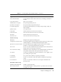
Application
Title
Part Number
Format
Location
Switch
installation
Sun Storage Fibre Channel Switch
5802 Installation Guide
820-4969-xx
PDF
Online
Manage the
switch
Sun Storage Fibre Channel Switch
5802 QuickTools User Guide
820-4972-xx
PDF
Online
Manage the
switch
Sun Storage Fibre Channel Switch
820-4960-xx
5802 Command Line Interface Guide
PDF
Online
Command
line interface
reference
Command Line Interface Quick
Reference Guide
820-4962-xx
PDF
Online
Event Message Guide
Look up
messages and
correct
problems
820-4971-xx
PDF
Online
Manage the
switch
Simple Network Management
Protocol Reference Guide
820-4974-xx
PDF
Online
Manage the
switch
CIM Agent Reference Guide
820-4959-xx
PDF
Online
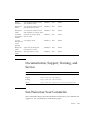
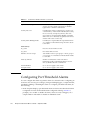
Documentation, Support, Training, and
Service
Sun Function
URL
Documentation
http://www.sun.com/documentation/
Support
http://www.sun.com/support/
Training
http://www.sun.com/training/
Service
http://www.sun.com/service/contacting/index.xml
Sun Welcomes Your Comments
Sun is interested in improving its documentation and welcomes your comments and
suggestions. You can submit your comments by going to:
Preface
xxi
http://www.sun.com/hwdocs/feedback
Please include the title and part number of your document with your feedback:
Enterprise Fabric Suite 2007 User Guide, part number 820-4966-10.
xxii
Enterprise Fabric Suite 2007 User Guide • September 2008
CHAPTER
1
Using Enterprise Fabric Suite 2007
This section describes how to use the Enterprise Fabric Suite 2007 application and its
menus. The following topics are covered:
■
Workstation Requirements
■
Installing Enterprise Fabric Suite 2007
■
Starting Enterprise Fabric Suite 2007
■
Exiting Enterprise Fabric Suite 2007
■
Uninstalling Enterprise Fabric Suite 2007
■
Changing the Encryption Key for the Default Fabric View File
■
Saving and Opening Fabric View Files
■
Setting Enterprise Fabric Suite 2007 Preferences
■
Using Online Help
■
Viewing Software Version and Copyright Information
■
Enterprise Fabric Suite 2007 User Interface
■
Using the Topology Display
■
Using the Faceplate Display
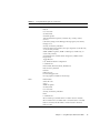
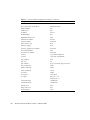
Workstation Requirements
The requirements for fabric management workstations running Enterprise Fabric
Suite 2007 are described in TABLE 1-1:
1
TABLE 1-1
Workstation Requirements
Operating System
•
•
•
•
Windows 2003, XP SP1/SP2
Solaris™ 9, 10, and 10 x86 Operating System (Solaris OS)
Red Hat Enterprise Linux 4, 5
SUSE Linux Enterprise Server 9, 10
Memory
512 MB or more (1GB recommended)
Disk Space
150 MB per installation
Processor
1 GHz or faster
Hardware
CD-ROM drive, RJ-45 Ethernet port, RS-232 serial port (optional)
Internet Browser
(to view online help)
• Microsoft Internet Explorer 6.0 and later
• Netscape Navigator 6.0 and later
• Firefox 1.5 and later
Installing Enterprise Fabric Suite 2007
You can install Enterprise Fabric Suite 2007 on a Windows, Linux, or Solaris OS
workstation using the Enterprise Fabric Suite 2007 Installation Disk.
Note – Contact your switch distributor or authorized reseller to purchase Enterprise
Fabric Suite 2007.
To install the Enterprise Fabric Suite 2007 application, do the following:
For a Windows platform:
1. Close all programs currently running, and insert the Enterprise Fabric Suite 2007
Installation Disk into the management workstation CD-ROM drive.
2. In the upper left corner of the product introduction screen, click Management
Software.
3. Locate your platform in the table and click Install.
If the product introduction screen does not open in step 2, open the CD with
Windows Explorer and run the installation program with the following path:
data\files\Management_Software\Windows\Windows_7.04.xx.xx.exe
For a Linux platform:
Open the CD and run the installation program with the following path:
2
Enterprise Fabric Suite 2007 User Guide • September 2008
data/files/Management_Software/Linux/Linux_7.04.xx.xx.bin
If there is no CD-ROM icon, do the following:
1. Open an xterm or other terminal window.
2. Mount the CD-ROM. From a shell prompt, enter the following:
mount /mnt/cdrom
3. Change directory to the location of the install program:
cd /mnt/cdrom/data/files/Management_Software/Linux
4. Execute the install program and follow the installation instructions.
Linux_7.04.xx.xx.bin
For a Solaris OS platform:
1. Open a terminal window. If the disk isn’t already mounted, enter the following
command:
volcheck
2. Enter following command to move to the directory on the CD that contains the
executable:
cd /cdrom/cdrom0/data/files/Management_Software/solaris
3. Execute the install program and follow the installation instructions:
Solaris_7.04.xx.xx.bin
Starting Enterprise Fabric Suite 2007
To start Enterprise Fabric Suite 2007 for the first time, do the following.
1. Start the Enterprise Fabric Suite 2007 application using one of the following
methods:
■
For Windows, double-click the Enterprise Fabric Suite 2007 shortcut, or
select Enterprise Fabric Suite 2007 from Start menu, depending on how you
installed the application. From a command line, enter the following
command:
<install_directory>\Enterprise_Fabric_Suite_2007.exe
■
For Linux or Solaris OS enter the Enterprise_Fabric_Suite_2007 command:
Chapter 1
Using Enterprise Fabric Suite 2007
3
<install_directory>./Enterprise_Fabric_Suite_2007
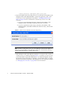
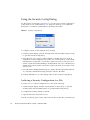
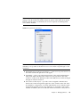
2. The serial number/license key dialog allows you to enter the serial number on the
Enterprise Fabric Suite 2007 CD ROM to activate the application, and to enter
license keys you have purchased, if any. Refer to “Installing Feature License
Keys” on page 154 for more information on license keys. Choose one of the
following:
■
If you have not purchased license keys, enter the serial number on the
Enterprise Fabric Suite 2007 CD ROM and click the Save button.
■
If you have purchased a license key(s), enter the serial number on the
Enterprise Fabric Suite 2007 CD ROM, enter the license keys, and click the
Save button.
FIGURE 1-1
Enter CD Serial Number and License Key Dialog
Note – If this is not the first session, you can update the current serial number or
license key. Open the Help menu and select License Info. On information dialog,
click the Enter Key button to openthe dialog below.
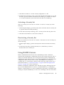
3. When Enterprise Fabric Suite 2007 first establishes a connection with a switch, for
security reasons, you will be prompted (FIGURE 1-2) to change your user account
password initially set up by the administrator. You will be prompted to change
the default password each time you attempt to open the fabric until you change
the password. Click the OK button, and change the user account password. Refer
to “Managing User Accounts” on page 104 for more information.
4
Enterprise Fabric Suite 2007 User Guide • September 2008
FIGURE 1-2
Password Change Required Dialog
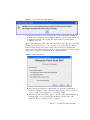
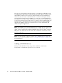
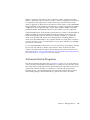
4. If this is the first time you are managing this switch, in the Initial Start dialog,
click the Open Configuration Wizard button. When you power-up the switch, the
Configuration Wizard will recognize the switch and lead you through the
configuration process.
When starting Enterprise Fabric Suite 2007 the first time, the application opens with
the Initial Start dialog (FIGURE 1-3). If you prefer not to see this dialog, select the
Don’t show this dialog again option. This has the same effect as disabling the
Display Initial Start Dialog preference. Refer to “Setting Enterprise Fabric Suite 2007
Preferences” on page 9 for information about setting preferences.
FIGURE 1-3
Initial Start Dialog
■
Select the Open Configuration Wizard option to open the Configuration
Wizard to configure a switch, add a new switch, replace/restore a switch, or
recover or edit an IP configuration of an existing switch.
■
Select the Open Existing Fabric option to open the Add a New Fabric dialog,
which prompts you for a fabric name, IP address, account name, and
password. Refer to “Adding a Fabric” on page 33.
Chapter 1
Using Enterprise Fabric Suite 2007
5
■
Select the Open Existing Fabric View File option to open the Open View dialog
which prompts you to specify a fabric view file that you saved earlier. Refer to
“Opening a Fabric View File” on page 35.
■
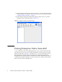
Select the Start Application Without Specifying a Fabric option to open the
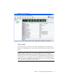
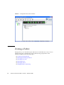
Enterprise Fabric Suite 2007 window (FIGURE 1-4).
FIGURE 1-4
Enterprise Fabric Suite 2007 Window
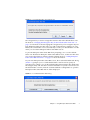
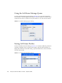
Exiting Enterprise Fabric Suite 2007
To exit a Enterprise Fabric Suite 2007 application session, open the File menu and
select Exit. If you have not yet saved the default fabric view file, the Save Default
Fabric View File dialog (FIGURE 1-5) prompts you to save the current fabric view as
the default fabric view file. Enter an encryption key in the Default Fabric File
Encryption Key field. Re-enter the encryption key in the Re-enter Encryption Key to
Confirm field. Click the OK button to save the current set of fabrics to the default
fabric view file in the working directory.
6
Enterprise Fabric Suite 2007 User Guide • September 2008
FIGURE 1-5
Save Default Fabric View File Dialog
The encryption key is used to encrypt the sensitive data in the default fabric view
file. Refer to “Changing the Encryption Key for the Default Fabric View File” on
page 8 for information about changing this encryption key. If an encryption key has
been defined and the View File Auto Save and Load preferences settings are set to
Enable, the current fabric view is automatically saved to your default fabric view file
when you close future Enterprise Fabric Suite 2007 sessions.
To prevent Enterprise Fabric Suite 2007 from prompting you to save the default
fabric view file between Enterprise Fabric Suite 2007 sessions, set the View File Auto
Save and Load preferences setting to Enable (default). Refer to “Setting Enterprise
Fabric Suite 2007 Preferences” on page 9 for more information.
In your next Enterprise Fabric Suite 2007 session, the Load Default Fabric File dialog
(FIGURE 1-6) prompts you to load the default fabric view file and to specify its
encryption key, if there is one. In the Default Fabric File Encryption Key field, enter
the encryption key and click the Load View File button. If you do not want to load
the default fabric view file, click the Continue Without Loading button to open the
Enterprise Fabric Suite 2007 with no fabric displayed.
FIGURE 1-6
Load Default Fabric File Dialog
Chapter 1
Using Enterprise Fabric Suite 2007
7
Uninstalling Enterprise Fabric Suite 2007
A program to uninstall Enterprise Fabric Suite 2007 was included as part of the
installation process. The UninstallerData folder in the Install directory contains the
uninstall program Uninstall_Enterprise Fabric Suite 2007. Also, a shortcut/link to
the uninstall program was installed in the installation directory during the
Enterprise Fabric Suite 2007 installation process.
The default installation directories are:
■
For Windows: C:\Program Files\Sun\Enterprise_Fabric_Suite_2007
■
For Linux: /opt/Sun/Enterprise_Fabric_Suite_2007
■
For Solaris OS: /usr/opt/Sun/Enterprise_Fabric_Suite_2007
To uninstall the Enterprise Fabric Suite 2007 application, do the following:
■
For Windows, browse for the uninstall program file or the shortcut/link that
points to the uninstall program file. The uninstall program shortcut is in the
same folder as the program shortcut (Start menu, program group, on desktop,
or user specified) that is used to start the Enterprise Fabric Suite 2007
application. Double-click the uninstall program file or shortcut/link, and
follow the instructions to uninstall the Enterprise Fabric Suite 2007 application.
■
For Linux or Solaris OS, execute the link to
Uninstall_Enterprise_Fabric_Suite_2007. If no links were created during the
installation, enter the Uninstall_Enterprise_Fabric_Suite_2007 command from
the following directory:
UninstallerData/Uninstall_Enterprise_Fabric_Suite_2007
Changing the Encryption Key for the
Default Fabric View File
To change the encryption key for the Enterprise Fabric Suite 2007 default fabric view
file, do the following:
1. Open the File menu and select Save Default Fabric View File to open the Save
Default Fabric View File dialog. Enter an encryption key in the Default Fabric File
Encryption Key field.
2. Re-enter the same encryption key in the Re-enter Encryption Key to Confirm
field.
8
Enterprise Fabric Suite 2007 User Guide • September 2008
3. Click the OK button to save the current set of fabrics to the default fabric view file
in the working directory.
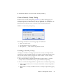
Saving and Opening Fabric View Files
A fabric view file is one or more fabrics saved to a file. In addition to the Enterprise
Fabric Suite 2007 default fabric view file, you can save and open your own fabric
view files. To save a set of fabrics to a file, do the following:
1. Open the File menu and select Save View As to open the Save View dialog.
2. Enter a name for the fabric view file or click the Browse button to select an
existing file. Files are saved in the working directory.
3. Enter a password. When you attempt to open this fabric view file, you will be
prompted for this password. If you leave the File Password field blank, no
password will be required when attempting to open this fabric view file.
4. Click the OK button to save the view.
To open a fabric view file, do the following:
1. Open the File menu and select Open View File to open the Open View dialog.
2. Enter a name for the fabric view file or click the Browse button to select an
existing file.
3. If the fabric view file was saved with a password, enter the password and click
the OK button.
4. Click the OK button to open the view.
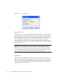
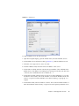
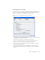
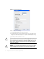
Setting Enterprise Fabric Suite 2007
Preferences
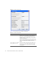
Using the Preferences dialog (FIGURE 1-7) you can:
■
Change the location of the working directory in which to save files.
■
Change the location of the browser used to view the online help.
Chapter 1
Using Enterprise Fabric Suite 2007
9
10
■
Enable (default) or disable the view file auto save and load feature. Refer to
“Exiting Enterprise Fabric Suite 2007” on page 6 for more information on the
default fabric view file.
■
Enable (default) or disable the use of the Initial Start Dialog at the beginning of
an Enterprise Fabric Suite 2007 session. Refer to “Starting Enterprise Fabric
Suite 2007” on page 3 for information about the Initial Start Dialog. After a
default fabric view file is created, this setting has no effect.
■
Enable (default) or disable the Non Secure Connections Check dialog that is
displayed when you attempt to open a non secure fabric. If Display Dialog
When Making Non-secure Connections is enabled, you can open a fabric with
a non-secure fabric. Otherwise, you must have a secure connection.
■
Enable (default) or disable the Event Browser. Refer to “Displaying the Event
Browser” on page 42. If the Event Browser is enabled using the Preferences
dialog (FIGURE 1-7), the next time Enterprise Fabric Suite 2007 is started, all
events will be displayed. If the Event Browser is disabled when Enterprise
Fabric Suite 2007 is started and later enabled, only those events from the time
the Event Browser was enabled and forward will be displayed.
■
Choose the default port view when opening the faceplate display. You can set
the faceplate to reflect the current port type (default), port speed, port
operational state, or port transceiver media. Regardless of the default port view
you choose, you can change the port view in the faceplate display by opening
the View menu and selecting a different port view option. Refer to the
corresponding subsection for more information:
■
“Displaying Port Types” on page 179
■
“Displaying Port Operational States” on page 180
■
“Displaying Port Speeds” on page 180
■
“Displaying Transceiver Media Status” on page 181
Enterprise Fabric Suite 2007 User Guide • September 2008
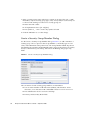
FIGURE 1-7
Preferences Dialog – Enterprise Fabric Suite 2007
To set preferences for your Enterprise Fabric Suite 2007 sessions, do the following:
1. Open the File menu, and select Preferences to open the Preferences dialog.
2. Enter or browse for the paths to the working directory and browser.
3. In the Application-wide Options area, choose the preferences you want.
4. Click the OK button to save the changes.
Using Online Help
The browser-based online help system can be accessed from the Enterprise Fabric
Suite 2007 application several ways. Online help is also context-sensitive, that is, the
online help opens to the topic that describes the dialog you have open.
To open the first topic in the help system, choose one of the following:
■
Open the Help menu and select Help Topics
■
Click the Help button in the tool bar
■
With no dialog displayed, press the F1 function key
To open the help system to the topic that describes the dialog you have open, choose
one of the following:
■
Click the Help button in the dialog
■
Press the F1 function key
Chapter 1
Using Enterprise Fabric Suite 2007
11
Viewing Software Version and
Copyright Information
To view Enterprise Fabric Suite 2007 software version and copyright information,
open the Help menu and select About.
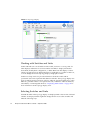
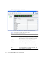
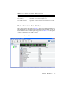
Enterprise Fabric Suite 2007 User
Interface
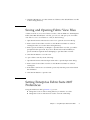
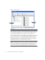
The Enterprise Fabric Suite 2007 application uses the topology display (FIGURE 1-8) to
manage the fabric. The topology display shows all switches in the fabric that are able
to communicate and all connections between switches. All display types share the
basic elements including fabric tree, menu bar, tool bar, graphic window, data
window, and data window tabs.
12
Enterprise Fabric Suite 2007 User Guide • September 2008
FIGURE 1-8
Topology Display Elements
1
2
3
4
7
5
6
Figure Legend
1
Menu Bar
5
Data Window
2
Tool Bar
6
Data Window Tabs
3
Switch/Fabric Name and Status
7
Fabric Tree
4
Graphic Window
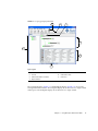
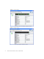
The faceplate display (FIGURE 1-9) and backplate display (FIGURE 1-10) are used to
manage individual switches. The faceplate display shows the front of a single switch
and its ports. The backplate display shows the back of a single switch.
Chapter 1
Using Enterprise Fabric Suite 2007
13
14
FIGURE 1-9
Faceplate Display
FIGURE 1-10
Backplate Display
Enterprise Fabric Suite 2007 User Guide • September 2008
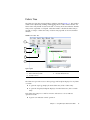
Fabric Tree
The fabric tree lists the managed fabrics and their switchesFIGURE 1-11. The window
width can be adjusted by clicking and dragging the moveable window border. An
fabric name entry handle located to the left of an entry in the tree indicates that the
entry can be expanded or collapsed. Click this handle or double-click the entry to
expand or collapse a fabric tree entry. A fabric entry expands to show its member
switches.
FIGURE 1-11
Fabric Tree
1
2
3
4
5
Figure Legend
1
Fabric Name Entry
4
Switch Entries
2
Fabric Name Entry Handle
5
Moveable Window Border
3
Security Lock Icon
The fabric tree provides access to the topology and faceplate displays for any fabric
or switch.
■
To open the topology display from the fabric tree, click a fabric entry.
■
To open the faceplate/backplate displays from the fabric tree, click a switch
entry.
Each fabric tree entry has a small icon next to it that uses color to indicate
operational status.
■
A green icon indicates normal operation.
Chapter 1
Using Enterprise Fabric Suite 2007
15
■
A yellow icon indicates the switch is operational, but may require attention to
maintain maximum performance.
■
A red icon indicates a potential failure or non-operational state as when the
switch is offline.
■
A blue icon indicates that a switch is unknown, unreachable, or unmanageable.
If the status of the fabric is not normal, the fabric icon in the fabric tree will indicate
the reason for the abnormal status. The same message is provided when you rest the
mouse over the fabric icon in the fabric tree.
Note – The small lock icon next to the fabric icon in the fabric tree indicates a secure
fabric connection (SSL — Secure Socket Layer). The Security menu is available only
on a secure fabric and on the entry switch (out of band switch). Open the Switch
menu and select Services to enable the SSL option for that switch. You must then
close the fabric and re-establish a connection to secure the fabric using SSL.
Graphic Window
The graphic window (FIGURE 1-8) presents graphic information about fabrics and
switches such as the fabric topology and the switch faceplate. The window height
can be adjusted by clicking and dragging the window border that it shares with the
data window.
The faceplate display (FIGURE 1-9) shows the front of a switch. To view the faceplate
display, open the View menu, and select View Faceplate.
The backplate display (FIGURE 1-10) shows the back of the switch. To view the
backplate display, open the View menu, and select View Backplate.
Data Window and Tabs
The data window (FIGURE 1-8) presents a table of data and statistics associated with
the selected tab. Use the scroll bar to browse through the data. The window length
can be adjusted by clicking and dragging the border that it shares with the graphic
window.
Adjust the column width by moving the pointer over the column heading border
shared by two columns until a right/left arrow graphic is displayed. Click and drag
the arrow to the desired width.
The data window tabs present options for the type of information to display in the
data window. These options vary depending on the display.
16
Enterprise Fabric Suite 2007 User Guide • September 2008
Menus
The Enterprise Fabric Suite 2007 menus and the tasks offered in them vary
depending on the display. For example, the Port menu and many of the Switch menu
selections are only available in the faceplate display. Refer to “Topology Display
Menu” on page 17 and “Faceplate Display Menu” on page 18 for information on the
menus.
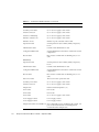
Topology Display Menu
TABLE 1-2 lists the topology display menu options.
TABLE 1-2
Topology Menu Options
Menu
Options
File
Open View File
Save View As
Save Default Fabric View File
Preferences
Exit
Fabric
Add Fabric
Remove Fabric
Nicknames
Fabric Tracker
Security Consistency Checklist
Rediscover Fabric
Start Performance View
FC TraceRoute (requires SANdoctor license key)
Show Event Browser
Switch
Delete (available only if one switch is selected)
Export Devices
Switch Properties (available only if one switch is selected)
Network Properties (available only if one switch is selected)
SNMP Properties (available only if one switch is selected)
Delete
Stack (these options
are available only if
Syslog
one stack is selected in SNMP Properties
the graphic window)
Set Date/Time
User Accounts
Security Consistency Checklist
Load Firmware
Edit Zoning Configuration
Chapter 1
Using Enterprise Fabric Suite 2007
17
TABLE 1-2
Topology Menu Options (Continued)
Menu
Options
View
Refresh
Layout Topology
Toggle Auto Layout
Remember Layout
Wizards
Configuration Wizard
Help
Help Topics
License Info
About
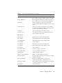
Faceplate Display Menu
TABLE 1-3 lists the faceplate display menu options.
TABLE 1-3
18
Faceplate Menu Options
Menu
Options
File
Open View File
Save View As
Save Default Fabric View File
Preferences
Exit
Fabric
Add Fabric
Remove Fabric
Nicknames
Fabric Tracker
FC TraceRoute (requires SANdoctor license key)
Show Event Browser
Enterprise Fabric Suite 2007 User Guide • September 2008
TABLE 1-3
Faceplate Menu Options (Continued)
Menu
Options
Switch
Archive
Restore
User Accounts
Set Date/Time
Switch Properties
Advanced Switch Properties (available only on entry switch)
Services
Call Home (Setup, Profile Manager, Message Queue, Test Profile,
Change Over)
Security Consistency Checklist
Network (Network Properties, IPv6 Ipsec Properties (available only
on secure entry switch))
SNMP (SNMP Properties, SNMP v3 Manager (available only on
secure entry switch))
Switch Diagnostics (Online Switch Diagnostics, Offline Switch
Diagnostics)
Toggle Beacons
Port Threshold Alarm Configuration
Load Firmware
Reset Switch (Hot Reset, Reset, Hard Reset)
Restore Factory Defaults
Features
Radius Servers
Download Support File
FC Ping (requires SANdoctor license key)
Stack
Refresh Stack
Select All Ports
Syslog
SNMP Properties
Set Date/Time
User Accounts
Security Consistency Checklist
Reset
Load Firmware
Move Switch Up (available when a switch in stack is selected)
Move Switch Down (available when a switch in stack is selected)
Remove Switch (available when a switch in stack is selected)
Remove Links
Chapter 1
Using Enterprise Fabric Suite 2007
19
TABLE 1-3
Faceplate Menu Options (Continued)
Menu
Options
Port
Port Properties
Advanced Port Properties
Reset Port
Port Binding
Port Diagnostics (requires SANdoctor license key)
Move Port
Zoning
Edit Zoning
Resolve Zoning (Capture Active Zoning, Restore Configured Zoning,
Capture Merged Zoning, View Merged/Configured Differences)
Edit Zoning Config
Activate Zone Set
Deactivate Zone Set
Restore Default Zoning
Security
Edit Security
Edit Security Config
Activate Security Set
Deactivate Security Set
View
Refresh
View Port Types
View Port States
View Port Speeds
View Port Media
View Faceplate
View Backplate
Wizards
Configuration Wizard
Extended Credit Wizard
Zoning Wizard
Help
Help Topics
License Info
About
Menu Shortcut Keys
Shortcut key combinations, available in both the topology and faceplate displays,
provide an alternative method of accessing menu options in the application. For
example, to exit the application, press Alt+F, then press X. The shortcut key
combinations are not case-sensitive.
20
Enterprise Fabric Suite 2007 User Guide • September 2008
Press the F1 function key to open the online help system. With no dialog displayed,
the online help system opens to the first topic. With a dialog displayed, the help
system opens to the topic describing that dialog.
Popup Menus
Popup (or shortcut) menus provide quick access to the menu options within the
current context of the application. They are displayed when you right-click on
certain areas of the topology or faceplate displays, such as inside the graphic
window of the topology display, or on a port on the faceplate display. The options
available in popup menus vary by display type (topology or faceplate) and where
you click.
Note – Additionally, mouse-over information is displayed when you rest the cursor
over key elements in the Enterprise Fabric Suite 2007 interface, such as ports, LEDs,
and fabric tree entries.
Opening the Topology Popup Menus
The topology display also offers a fabric, switch, and a link popup menu:
■
To open the fabric popup menu, right-click the graphic window background.
The fabric popup menu presents selections to refresh the fabric, select all
switches, select all links, or layout topology.
■
To open the switch popup menu, right-click the switch icon in the graphic
window. The switch popup menu presents selections to refresh the switch,
delete the switch from the display, open the Switch Properties dialog, or open
the Network Properties dialog.
■
To open the link popup menu, right-click the link. The Link popup menu
presents a selection to delete the link from the display.
Opening the Faceplate Popup Menus
To open the faceplate popup menu, right-click the faceplate image. The faceplate
popup menu presents selections to refresh the switch, select all ports, open the
Switch Properties dialog, open the Network Properties dialog, open the SNMP
Properties dialog, use the Extended Credits Wizard, open the Port Properties dialog,
run port diagnostic tests, configure RADIUS servers, open the Services dialog, and
view the Security Consistency Checklist dialog.
Chapter 1
Using Enterprise Fabric Suite 2007
21
If no ports are selected, the port-related tasks will be unavailable in the popup
menu. Right-click a port to open the corresponding popup menu. Press the Shift or
Control key to select more than one port. If multiple ports are selected, right-click
one of the selected ports.
Tool Bar
The tool bar consists of a row of graphical buttons that you can use to access
Enterprise Fabric Suite 2007 functions. The tool bar buttons are an alternative
method to using the menu bar. TABLE 1-4 describes the tool bar buttons.
TABLE 1-4
Button
Tool Bar Buttons
Description
Add Fabric — adds a new fabric to the fabric view.
Open View File — opens an existing fabric view file.
Save View As — saves the current fabric view to a file.
Refresh — updates the topology or faceplate display with current
information.
Event Browser — opens the events browser.
Edit Zoning — opens the Edit Zoning dialog (available only in
faceplate/backplate displays).
22
Enterprise Fabric Suite 2007 User Guide • September 2008
TABLE 1-4
Button
Tool Bar Buttons (Continued)
Description
Edit Security — opens the Edit Security dialog (faceplate/backplate
displays on entry switch that has a secure fabric connection (SSL
enabled).
Help Topics — opens the online help file.
The Sun Microsystems logo opens a browser to the Sun Microsystems
Web site.
Using the Topology Display
The topology display (FIGURE 1-12) receives information from the selected fabric and
displays its topology. Switches and inter-switch links (ISLs) appear in the graphic
window and use color to indicate status.
■
Working with Switches and Links
■
Selecting Switches and Links
■
Arranging Switches in the Topology Display
■
Topology Data Windows
Note – Mouse-over information is displayed when you rest the cursor over key
elements in the Enterprise Fabric Suite 2007 interface, such as ports LEDs, and fabric
tree entries.
Chapter 1
Using Enterprise Fabric Suite 2007
23
FIGURE 1-12
Topology Display
Working with Switches and Links
Switch and link icons are selectable and moveable, and serve as access points for
other displays and menus. You select switches and links to display information
about them, modify their configuration, or delete them from the display. Contextsensitive popup menus are displayed when you right-click on a switch or link icon,
or in the background of the topology display and graphic window.
Switch icon shape and color provide information about the switch and its
operational state. Lines represent links between switches. The topology display uses
green to indicate normal operation, yellow to indicate operational with errors, red to
indicate a potential failure or non-operational state, and blue to indicate unknown,
unreachable, or unmanageable. Refer to “Displaying Fabric Status” on page 41 for
more information about topology display icons.
Selecting Switches and Links
Selected ISL links in the topology display are displayed with a heavier line. Selected
switches are displayed with a light blue background. You can select switches and
links the following ways:
24
Enterprise Fabric Suite 2007 User Guide • September 2008
■
To select one switch or link, click the switch or link.
■
To select a group of switches or links, press the Shift or Control key while
clicking each switch or link.
■
To select all switches or links, right-click anywhere in the graphic window
background, and select Select All Links or Select All Switches from the popup
menu.
■
To cancel all selections, click in the background of the graphic window.
■
To un-select one switch or link in a group of selected switches and/or links,
press the Shift or Control key while clicking the switch or link.
■
To add a switch or link to a group of selected switches and/or links, press the
Shift or Control key while clicking the switch or link.
Arranging Switches in the Topology Display
You can arrange individual switch icons in the topology display or allow Enterprise
Fabric Suite 2007 to arrange all switch icons for you:
■
To move an individual switch icon, click and drag the icon to another location
in the graphic window. Links stretch or contract to remain connected.
■
To arrange all switch icons in the topology display automatically, open the
View menu and select Layout Topology.
By default, the Toggle Auto Layout box in the View menu is selected which causes
Enterprise Fabric Suite 2007 to arrange the icons when you select Layout Topology.
You can save a custom arrangement, or layout, and restore that layout during a
Enterprise Fabric Suite 2007 session. Begin by arranging the icons, then open the
View menu and select Remember Layout. To restore the saved layout, open the View
menu, unselect the Toggle Auto Layout option, and select Layout Topology.
Topology Data Windows
The topology display provides the following data windows corresponding to the
data window tabs:
■
Devices — displays all devices logged with the name server and their
addresses within the current fabric configuration, and displays information
from the fabric and allows devices to register certain information with the
fabric. Refer to “Devices Data Window” on page 40 for more information.
■
Active Zoneset — displays the active zone set for the fabric including zones
and their member ports. Refer to “Active Zoneset Data Window” on page 58
for more information about this data window. Refer to “Zoning a Fabric” on
page 60 for information about zone sets and zones.
Chapter 1
Using Enterprise Fabric Suite 2007
25
■
Switch — displays current network and switch configuration data for the
selected switches. Refer to “Switch Data Window” on page 109 for more
information.
■
Link — displays information about the inter-switch links. Refer to “Link and
Stack Link Data Windows” on page 39 for more information.
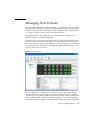
Using the Faceplate Display
The faceplate display (FIGURE 1-13) shows the front of a single switch, the switch
name, the switch operational state, the ports, and the port status. To open the
faceplate display when viewing the topology display, click the switch name/icon in
the fabric tree, or double-click the switch icon in the graphic window.
■
Alerts Panel
■
Port Views and Status
■
Working with Ports
■
Faceplate Data Windows
Note – Additionally, mouse-over information is displayed when you rest the cursor
over key elements in the Enterprise Fabric Suite 2007 interface, such as ports, LEDs,
and fabric tree entries.
26
Enterprise Fabric Suite 2007 User Guide • September 2008
FIGURE 1-13
Faceplate Display
Alerts Panel
The Alerts Panel shows all reasons for status, including faults. The Alerts Panel
entries are the highlighted rows between the faceplate image and the data window
entries.
Note – The up/down arrows on the divider bar (between the Alerts Panel entries
and data windows) enable you to move the divider bar up or down. With the
faceplate image and data windows displayed, click the up arrow (on left) to move
the divider up to the top of the window, thus completely hiding the faceplate image.
Click the down arrow (on right) to move the divider back to the middle; click the
down arrow again to completely hide the data window. You can also click-and-drag
the divider bar to manually move it up or down.
Chapter 1
Using Enterprise Fabric Suite 2007
27
FIGURE 1-14
Alerts Panel
1
2
Figure Legend
1
Alerts Panel Entries
2
Move Divider Arrows
Port Views and Status
Port color and text provide information about the port and its operational state.
Green indicates active; gray indicates inactive. The faceplate display provides the
following views of port status corresponding to the View menu options in the
faceplate display. Refer to “Monitoring Port Status” on page 179 for more
information about these displays.
28
■
Port type
■
Port state
■
Port speed
■
Port media
Enterprise Fabric Suite 2007 User Guide • September 2008
Working with Ports
Ports are selectable and serve as access points for other displays and menus. You
select ports to display information about them in their respective data windows or to
modify them. Context-sensitive popup menus and properties windows are accessible
through the port icons.
Selecting Ports
Selected ports in the faceplate display are outlined in light-blue.
Note – When using the Shift key to select a range of ports, the first port you click in
the range is the "anchor" selection. Subsequent ranges are based on this anchor
selection. For example, after clicking port 4 and port 9 respectively, port 4 becomes
the anchor selection. The next range includes all ports between port 4 and the next
port you select.
You can select ports the following ways.
■
To select a port, click the port.
■
To un-select a port, click outside that port.
■
To select all ports, right-click on the faceplate image and select Select All Ports
from the popup menu.
■
To select a range of consecutive ports, click a port, press the Shift key and click
another port. The application selects both end ports and all ports in between
the end ports.
■
To select several non-consecutive ports, press the Control key while clicking
each port.
■
To un-select ports in a group of selected ports, press the Control key while
clicking each port.
Faceplate Data Windows
The faceplate display provides the following data windows corresponding to the
data window tabs:
■
Devices — displays information about devices (hosts and storage targets)
connected to the switch. Refer to “Devices Data Window” on page 40 for more
information.
■
Switch — displays current switch configuration data. Refer to “Switch Data
Window” on page 109 for more information.
Chapter 1
Using Enterprise Fabric Suite 2007
29
30
■
Stack Links — displays information about the links between all switches in the
stack.
■
Port Statistics — displays performance data for the selected ports. Refer to
“Port Statistics Data Window” on page 169 for more information.
■
Port Information — displays information for the selected ports. Refer to “Port
Information Data Window” on page 173 for more information.
■
Configured Zonesets — displays all zone sets, zones, and zone membership in
the zoning database. Refer to “Configured Zonesets Data Window” on page 59
for more information.
■
Configured Security — displays all security definitions currently saved in the
database. Refer to “Configured Security Data Window” on page 82 for more
information.
■
Active Security — displays the active security set. Refer to “Active Security
Data Window” on page 83 for more information.
Enterprise Fabric Suite 2007 User Guide • September 2008
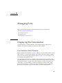
CHAPTER
2
Managing Fabrics
This section describes the following fabric management tasks:
■
Tracking Fabric Firmware and Software Versions
■
Managing the Fabric Database
■
Displaying Fabric Information
■
Verifying Fibre Channel Connections
■
Working with Device Information and Nicknames
■
Enabling Fabric Services
Tracking Fabric Firmware and Software
Versions
The Fabric Tracker option allows you to generate a snapshot or baseline of current
system version information, which can be viewed, analyzed and compared to other
snapshot files, and exported to a file. Information includes date and time, switch
active firmware version, device hardware, drivers, and firmware version from FDMI.
The Snapshot Analyzer option allows you to:
■
Compare two snapshots
■
Detect mismatches of firmware and driver versions
■
Detect devices that have been moved, added to or removed from the fabric.
31
Saving a Version Snapshot
To save the current snapshot to an XML file, do the following:
1. In the faceplate display, open the Fabric menu and select Fabric Tracker, and then
select Save Snapshot.
2. Enter a filename.
3. Click the Save button to save the snapshot as an XML file.
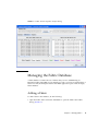
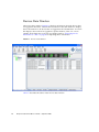
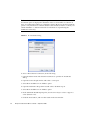
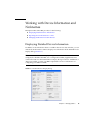
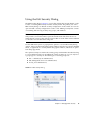
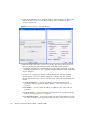
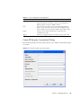
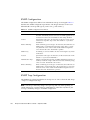
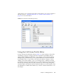
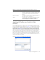
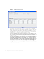
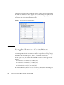
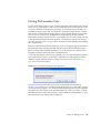
Viewing and Comparing Version Snapshots
To view and analyze system version information, open the Fabric menu, select
Fabric Tracker, and select Analyze Snapshots. The Fabric Version Snapshot Analysis
dialog (FIGURE 2-1) opens with the Summary, Differences and Reports tab pages.
Click the Browse buttons to open and view the snapshot files in the corresponding
tab pages. Click the Close button to exit the Fabric Version Snapshot Analysis dialog.
The color key below the scrollable area defines the meanings of the colors used. The
Summary tab page shows a brief description of the changes that have occurred
between the older snapshot and the newer one. Use the Summary tab page to
quickly view what has changed. The Differences tab page shows a side-by-side
comparison of two snapshots.
The timestamp of each snapshot is displayed above the scroll area showing that
snapshot. The background color of the older snapshot is darker than the background
of the newer snapshot. The arrow icon between the snapshot selectors always points
from the older snapshot to the newer one. If the two snapshots have the same
timestamp, the arrow will not be displayed. The scroll bars are synchronized to view
the same portion of each snapshot file simultaneously. Click and drag the separator
bar between the two panes to resize each pane. At the top of the separator bar
between the two panes, click the left/right arrows to close the corresponding pane.
The left/right arrows move to one side.
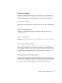
Exporting Version Snapshots to a File
The Reports tab page allows you to select one report to save to a text file. There are
two types of reports. The Summary report type shows the same format displayed on
the Summary tab page without the color highlighting. The Detail report type shows
a detailed breakdown of the differences. Use the Export button to save the selected
report to a text file.
32
Enterprise Fabric Suite 2007 User Guide • September 2008
FIGURE 2-1
Fabric Version Snapshot Analysis Dialog
Managing the Fabric Database
A fabric database contains the set of fabrics that you have added during an
Enterprise Fabric Suite 2007 session. Initially, if you do not open an existing fabric or
fabric view file, the Enterprise Fabric Suite 2007 application opens with an empty
fabric database.
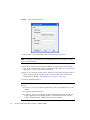
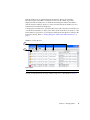
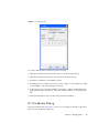
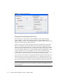
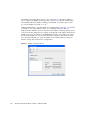
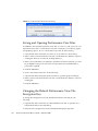
Adding a Fabric
To add a fabric to the database, do the following:
1. Open the Fabric menu and select Add Fabric to open the Add a New Fabric
dialog (FIGURE 2-2).
Chapter 2
Managing Fabrics
33
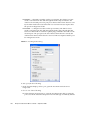
FIGURE 2-2
Add a New Fabric Dialog
2. Enter a fabric name in the Fabric Name field. This step is optional.
Note – Assigning a fabric name is recommended. However, if you enter a fabric
name, it must be unique.
3. In the Entry Switch field, enter the IP address or Domain Name Server (DNS)
name of the switch through which to manage the fabric. Refer to “IPv4 and IPv6
Addressing” on page 138 for more information.
4. Enter an account name and password. The factory login name and password are
"admin" and "password". The password is for the switch and is stored in the
switch firmware. Refer to “Managing User Accounts” on page 104.
5. Click the Add Fabric button.
Note – A switch supports a combined maximum of 19 logins or sessions reserved as
follows:
34
■
4 logins or sessions for internal applications such as management server and
SNMP
■
9 high priority Telnet sessions
■
6 logins or sessions for Enterprise Fabric Suite 2007 inband and out-of-band
logins, Application Programming Interface (API) inband and out-of-band
logins, and Telnet logins. Additional logins will be refused.
Enterprise Fabric Suite 2007 User Guide • September 2008
6. For security reasons, you will be prompted (FIGURE 1-2) to change your user
account password initially set up by the administrator. You will be prompted to
change the password each time you attempt to open the fabric until you change
the password. Click the OK button, and change the user account password. Refer
to “Managing User Accounts” on page 104 for more information.
Note – If the entry switch has SSL (Secure Socket Layer) enabled, the switch will
generate and display a Verify Certificate dialog that you must accept before gaining
access to the fabric. Refer to “Connection Security” on page 80 and for more
information on certificates and SSL.
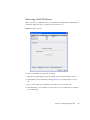
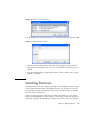
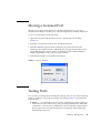
Removing a Fabric
To delete a fabric from the database, do the following:
1. Select a fabric in the fabric tree.
2. Open the Fabric menu and select Remove Fabric.
Note – The Closing Sessions dialog is then displayed with the status of closing the
fabric sessions. Click the OK button to close the dialog.
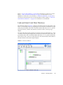
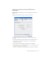
Opening a Fabric View File
A fabric view file is one or more fabrics saved to a file. To open an existing view file,
do the following:
1. Open the File menu and select Open View File, or click the Open button. If the
fabric you are currently viewing has changed, you will be prompted to save the
changes to the fabric view file with the Save View dialog before opening a
different view file.
2. In the Open View dialog, enter the name of the file to open, and enter a file
password, if a password was entered when this fabric view file was saved.
3. Click the OK button.
Note – To maximize system performance and reduce the fabric event logs, limit the
number of large fabrics open at one time.
Chapter 2
Managing Fabrics
35
Saving a Fabric View File
To save a fabric view file, do the following:
1. Open the File menu, and select Save View As.
2. In the Save View dialog, enter a new file name.
3. Enter a file password, if necessary.
4. Click the OK button.
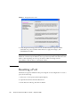
Rediscovering a Fabric
The rediscover fabric option clears out the current fabric information being
displayed, and rediscovers all switch information. To rediscover a fabric, open the
Fabric menu, and select Rediscover Fabric. The rediscover function is more
comprehensive than the refresh function.
Deleting Switches and Links
The Enterprise Fabric Suite 2007 application does not automatically delete switches
or links that have failed or have been physically removed from the fabric Fibre
Channel network. In these cases, you can delete switches and links to bring the
display up to date. If you delete a switch or a link that is still active, the Enterprise
Fabric Suite 2007 application will restore it automatically. You can also refresh the
display. To delete a switch from the topology display, do the following:
1. Select a switch in the topology display.
2. Open the Switch menu and select Delete.
To delete a link, do the following:
1. Select a link in the topology display.
2. Right-click the link and select Delete from the popup menu.
Adding a New Switch to a Fabric
If there are no special conditions to be configured for the new switch, simply plug in
the switch and the switch becomes functional with the default fabric configuration.
The default fabric configuration settings are:
36
Enterprise Fabric Suite 2007 User Guide • September 2008
■
Fabric zoning is sent to the switch from the fabric.
■
All ports will be GL_Ports.
■
The default IP address 10.0.0.1 is assigned to the switch without a gateway or
boot protocol configured (RARP, BOOTP, and DHCP).
If you are adding a switch to a fabric and do not want to accept the default fabric
configuration, do the following:
1. If the switch is not new from the factory, reset the switch to the factory
configuration before adding the switch to the fabric by selecting Restore Factory
Defaults in the Switch menu from the faceplate display.
2. If you want to manage the switch through the Ethernet port, you must first
configure the IP address using the Network Properties dialog or the
Configuration Wizard.
3. Configure any special switch settings. To open the Zoning Config dialog, open
the Zoning menu, and select Edit Zoning Config.
4. Plug in the inter-switch links (ISL), but do not connect the devices.
5. Configure the port types for the new switch using the Port Properties dialog. The
ports can be G_Port, GL_Port, F_Port, FL_Port, or Donor.
6. Connect the devices to the switch.
7. Make any necessary zoning changes using the Edit Zoning dialog. To open the
Edit Zoning dialog, open the Zoning menu, and select Edit Zoning. To open the
Zoning Config dialog, open the Zoning menu, and select Edit Zoning Config.
Replacing a Failed Switch
The archive/restore works for all switches. However, the Restore menu item is not
available for the in-band switches. You can only restore a switch out-of-band (the
fabric management switch). Enterprise Fabric Suite 2007 will archive and restore
only the settings that can be configured with Enterprise Fabric Suite 2007. Refer to
“Archiving a Switch” on page 130 and “Restoring a Switch” on page 131 for
information about archive and restore. Use the following procedure to replace a
failed switch for which an archive is available.
1. At the failed switch:
a. Turn off the power and disconnect the AC power cords.
b. Note port locations and remove the interconnection cables and SFPs.
c. Remove the failed switch.
Chapter 2
Managing Fabrics
37
2. At the replacement switch:
a. Mount the switch in the location where the failed switch was removed.
b. Install the SFPs using the same ports as were used on the failed switch.
Caution – Do not reconnect inter-switch links, target devices, and initiator devices
at this time. Doing so could invalidate the fabric zoning configuration.
c. Attach the AC power cords and power up the switch.
3. Select the failed switch in the topology display. Open the Switch menu and select
Delete.
4. Restore the configuration from the failed switch to the replacement switch:
a. Open a new fabric to the replacement switch.
b. Open the faceplate display for the replacement switch. Open the Switch menu
and select Restore.
c. In the Restore dialog, enter the archive file from the failed switch or browse for
the file.
d. Click the Restore button.
5. Reset the replacement switch to activate the configuration formerly possessed by
the failed switch including the domain ID and the zoning database. Open the
Switch menu and select Reset Switch.
6. Reconnect the inter-switch links, target devices, and initiator devices to the
replacement switch using the same ports as were used on the failed switch.
Displaying Fabric Information
The topology display is your primary tool for monitoring a fabric. The graphic
window of the topology display provides status information for switches, interswitch links, and the Ethernet connection to the management workstation. Refer to
Link data window (FIGURE 2-3) for more information.
The topology display data windows show device, active zone set, switch, and link
information.
38
Enterprise Fabric Suite 2007 User Guide • September 2008
Refer to “Devices Data Window” on page 40 for information on devices in a fabric.
Refer to “Active Zoneset Data Window” on page 58 for information on zone
definitions for the active zone set. Refer to “Switch Data Window” on page 109 for
information about the Name Server and Switch data windows. Refer to “Link and
Stack Link Data Windows” on page 39 for information on switch links.
Link and Stack Link Data Windows
The Link data window (FIGURE 2-3) displays information about all switch links in the
fabric or selected links in the topology display. This information includes the switch
name, the port number at the end of each link, and the link status icon. To open the
Link data window, click the Link tab below the data window in the topology
display.
The Stack Links data window displays information about all switch links for a stack
of switches in the faceplate display. This information includes the switch names, the
port number at the end of each link, and the link status icon. To open the Stack Links
data window, click a stack icon in the fabric tree, and click the Stack Links tab below
the data window in the stack faceplate display.
FIGURE 2-3
Link Data Window
Chapter 2
Managing Fabrics
39
Devices Data Window
The Devices data window (FIGURE 2-4) displays information about the devices that
are logged into the fabric. Click the Devices tab below the data window to display
device information for all devices that are logged into the selected fabric. To narrow
the display to devices that are logged into specific switches, select one or more
switches in the fabric tree or the topology display. Refer to “Exporting Device
Information to a File” on page 50 for exporting device information.
FIGURE 2-4
Devices Data Window
TABLE 2-1 describes the entries in the Devices data window.
40
Enterprise Fabric Suite 2007 User Guide • September 2008
TABLE 2-1
Devices Data Window Entries
Entry
Description
Port WWN
Port world wide name
Nickname
Device port nickname. To create a new nickname or edit an
existing nickname, double-click the cell and enter a nickname in
the Edit Nickname dialog. Refer to “Managing Nicknames for
Fabric Devices” on page 50 for more information.
Details
Click the (i) to display additional information about the device.
Refer to “Displaying Detailed Device Information” on page 49.
FC Address
Fibre Channel address
Switch
Switch name
Port
Switch port number
Target/Initiator
Device type: Target, Initiator, or Both
Vendor
Host Bus Adapter/Device Vendor
Active Zones
The active zone to which the device belongs
Row #
Row number reference for each listing in the Devices data
window table
Displaying Fabric Status
The fabric updates the topology and faceplate displays by forwarding changes in
status to the management workstation as they occur. You can allow the fabric to
update the display status, or you can refresh the display at any time. To refresh the
topology display, do one of the following:
■
Click the Refresh button.
■
Open the View menu and select Refresh.
■
Press the F5 key.
■
Right-click anywhere in the background of the topology display and select
Refresh Fabric from the popup menu.
The topology display uses switch and status icons to provide status information
about switches, inter-switch links, and the Ethernet connection. The switch status
icons, displayed on the left side of a switch, vary in shape and color. Switches
controlled by an Ethernet Internet Protocol have a colored Ethernet icon displayed
on the right side of the switch. A green Ethernet icon indicates normal operation,
yellow indicates a condition that may require attention to maintain maximum
performance, and red indicates a potential failure. TABLE 2-2 shows the different
switch icons and their meanings.
Chapter 2
Managing Fabrics
41
Note – Enterprise Fabric Suite 2007 may not support all firmware versions. If the
version of Enterprise Fabric Suite 2007 was not intended to support the firmware
version on the switch, a warning status of “FW/GUI mismatch” is displayed for the
switch. A switch with this status will still be manageable, but may preclude some
operations from being performed.
TABLE 2-2
Switch Icon
Topology Display Switch and Status Icons
Description
Switch status icons
• Normal operation (green)
• Warning–operational with errors (yellow)
• Critical–potential failure (red)
• Unknown–communication status unknown, unreachable,
or unmanageable (blue)
Fabric management switch Ethernet icons
• Ethernet connection normal (green)
• Ethernet connection warning (yellow)
• Ethernet connection critical (red)
Switch is not manageable with this version of Enterprise
Fabric Suite 2007. Use the management application that was
shipped with this switch.
Displaying the Event Browser
The Event Browser (FIGURE 2-5) displays a list of events generated by the switches in
the fabric and the Enterprise Fabric Suite 2007 application. Events that are generated
by the Enterprise Fabric Suite 2007 application are not saved on the switch, but can
be saved to a file during the Enterprise Fabric Suite 2007 session.
Entries in the Event Browser are formatted by severity, time stamp, source, type, and
description. The maximum number of entries allowed in the Event Browser is 10,000.
The maximum number of entries allowed on a switch is 1200. Once the maximum is
reached, the event list wraps and the oldest events are discarded and replaced with
the new events. Event entries from the switch, use the switch time stamp, while
event entries generated by the application have a workstation time stamp. You can
filter, sort, and export the contents of the Event Browser to a file. The Event Browser
begins recording when enabled and Enterprise Fabric Suite 2007 is running.
42
Enterprise Fabric Suite 2007 User Guide • September 2008
If the Event Browser is enabled using the Preferences dialog, the next time
Enterprise Fabric Suite 2007 is started all events from the switch log will be
displayed. If the Event Browser is disabled when Enterprise Fabric Suite 2007 is
started and later enabled, only those events from the time the Event Browser was
enabled and forward will be displayed.
To display the Event Browser, open the Fabric menu and select Show Event Browser,
or click the Events button on the tool bar. If the Show Event Browser selection or the
Events button is grayed-out, you must first enable the Events Browser setting in the
Preferences dialog. Refer to “Setting Enterprise Fabric Suite 2007 Preferences” on
page 9.
FIGURE 2-5
Events Browser
1
2
Figure Legend
1
Column Sorting Buttons
2
Severity Columns
Severity is indicated in the severity column using icons as described in TABLE 2-3.
Chapter 2
Managing Fabrics
43
TABLE 2-3
Severity Icon
Severity Levels
Description
Alarm — a "serviceable event". This means that attention by the user or
field service is required. Alarms are posted asynchronously to the screen
and cannot be turned off. If the alarm denotes that a system error has
occurred the customer and/or field representative will generally be directed
to provide a "show support" capture of the switch.
Critical event — an event that indicates a potential failure. Critical log
messages are events that warrant notice by the user. By default, these log
messages will be posted to the screen. Critical log messages do not have
alarm status as they require no immediate attention from a user or service
representative.
Warning event — an event that indicates errors or other conditions that may
require attention to maintain maximum performance. Warning messages
will not be posted to the screen unless the log is configured to do so.
Warning messages are not disruptive and, therefore, do not meet the criteria
of Critical. The user need not be informed asynchronously
No icon
Informative — an unclassified event that provides supporting information.
Note – Events (Alarms, Critical, Warning, and Informative) generated by the
application are not saved on the switch. They are permanently discarded when you
close a Enterprise Fabric Suite 2007 session, but you can save these events to a file on
the workstation before you close Enterprise Fabric Suite 2007 and read it later with a
text editor or browser.
Note – Events generated by the switch are stored on the switch, and will be
retrieved when the application is restarted. Some alarms are configurable. Refer to
“Configuring Port Threshold Alarms” on page 116.
Filtering the Event Browser
Filtering the Event Browser allows you to display only those events that are of
interest based on the event severity, timestamp, source, type, and description. To
filter the Event Browser, open the Filter menu and select Filter Entries. This opens
the Filter Events dialog (FIGURE 2-6). The Event Browser displays those events that
meet all of the criteria in the Filter Events dialog. If the filtering criteria is cleared or
changed, then all the events that were previously hidden that satisfy the new criteria
will be shown.
44
Enterprise Fabric Suite 2007 User Guide • September 2008
You can filter the event browser in the following ways:
■
Severity — select one or more of the corresponding options to display alarm
events, critical events, warning events, or informative events.
■
Date/Time — select one or both of the From: and To: options. Enter the
bounding timestamps (MM/DD/YY HH:MM AA) to display only those events
that fall within those times. ("AA" indicates AM or PM.) The current year (YY)
can be entered as either 2 or 4 digits. For example, 12/12/07 will be interpreted
December 12, 2007.
■
Text — select one or more of the corresponding options and enter a text string
(case sensitive) for event source, type, and description. The Event Browser
displays only those events that satisfy all of the search specifications for the
Source, Type, and Description text.
FIGURE 2-6
Filter Events Dialog
Sorting the Event Browser
Sorting the Event Browser allows you to display the events in alphanumeric order
based on the event severity, timestamp, source, type, or description. Initially, the
Event Browser is sorted in ascending order by timestamp. To sort the Event
Browser, click the Severity, Timestamp, Source, Type, or Description column
Chapter 2
Managing Fabrics
45
headings. You can also open the Sort menu and select By Severity, By Timestamp,
By Source, By Type, or By Description. Successive sort operations of the same type
alternate between ascending and descending order
Note – We recommend using unique fabric names and switch symbolic names to
better identify event log entries by source.
Saving the Event Browser to a File
You can save the displayed Event Browser entries to a file. Filtering affects the save
operation, because only displayed events are saved. To save the Event Browser to a
file, do the following:
1. Filter and sort the Event Browser to obtain the desired display.
2. Open the File menu and select Save As.
3. Select a folder and enter a file name in which to save the event log and click the
Save button. The file can be saved in XML, CSV, or text format. XML files can be
opened with an internet browser or text editor. CSV files can be opened with
most spreadsheet applications.
Verifying Fibre Channel Connections
Testing and tracing FC connections consists of utilizing the FC Ping and FC
TraceRoute dialogs to time and track frames from specified targets and destinations.
FC Ping Dialog
The FC Ping dialog (FIGURE 2-7) allows you to send an ECHO frame to a specified
target and verify the frame was returned.
Note – The SANdoctor™ license key for Sun Storage Fibre Channel Switch 5802 is
required to enable this feature. Contact your switch distributor or authorized reseller
for information on purchasing the SANdoctor license key.
46
Enterprise Fabric Suite 2007 User Guide • September 2008
FIGURE 2-7
FC Ping Dialog
To verify a Fibre Channel connection, do the following:
1. Open the Switch menu and select FC Ping to open the FC Ping dialog.
2. Open the Destination drop-down list and select a destination port.
3. Select the Port WWN or Port Address option.
4. In the Repeat area, use the arrow keys to select or type in a value (between 1-100)
for the number of FC ping attempts to perform.
5. In the Timeout area, select the number of seconds to continue attempting the FC
ping operation before timing out. Click and drag the slide bar to move the slide
bar.
6. Click the Ping button, and view the results in the text window.
FC TraceRoute Dialog
The FC TraceRoute dialog (FIGURE 2-8) allows you to map the route trip a frame takes
from source to destination and back.
Chapter 2
Managing Fabrics
47
Note – The SANdoctor license key is required to enable this feature. The FC
TraceRoute option is displayed in the Fabric menu on all switches in a fabric if at
least one switch in the fabric has a SANdoctor license. However, the FC TraceRoute
option is only functional on switches that have the SANdoctor license. Contact your
switch distributor or authorized reseller for information on purchasing the
SANdoctor license key.
FIGURE 2-8
FC TraceRoute Dialog
To trace a Fibre Channel connection, do the following:
1. Open the Fabric menu and select FC TraceRoute to open the FC TraceRoute
dialog.
2. Open the Source drop-down list and select a source port.
3. Select the Port WWN or Port Address option.
4. Open the Destination drop-down list and select a destination port.
5. Select the Port WWN or Port Address option.
6. In the Maximum Round-trip Hops list, use the arrow keys to select or type in a
value (between 1-32).
7. Click the Trace button, and view the results in the text window.
48
Enterprise Fabric Suite 2007 User Guide • September 2008
Working with Device Information and
Nicknames
Enterprise Fabric Suite 2007 provides for the following:
■
Displaying Detailed Device Information
■
Exporting Device Information to a File
■
Managing Nicknames for Fabric Devices
Displaying Detailed Device Information
In addition to the information that is available in the Devices data window, you can
click the (i) in the Details column to display more information in the Detailed Device
Display dialog (FIGURE 2-9).
Note – The Detailed Device Display dialog shows detailed information for HBAs
configured for FDMI. If the HBA is not configured for FDMI, supplemental and
vendor information in the Detailed Device Display dialog is listed as "Undefined" or
"Data Unavailable". Contact your HBA representative for more information on
configuring your HBA for FDMI.
FIGURE 2-9
Detailed Devices Display Dialog
Chapter 2
Managing Fabrics
49
Exporting Device Information to a File
To save device information to a file, open the topology display and do the following:
1. Select one or more switches in the graphic window. If no switches are selected,
Devices information is gathered for all switches.
2. Open the Switch menu and select Export Devices.
3. In the Save dialog, enter a file name. Select the extension for the type of output
file (CSV or text format) to be saved. CSV files can be opened with Microsoft
Excel or most spreadsheet applications.
4. Click the Save button.
Managing Nicknames for Fabric Devices
A nickname is a user-definable, meaningful name that can be used in place of the
world wide name. You can assign a nickname to a world wide name of a device.
Assigning a nickname makes it easier to recognize device ports when zoning your
fabric or when viewing the Devices data window. You can add, edit, delete, import
and export nicknames using the Nicknames dialog. A nickname must start with a
letter and can have up to 64 characters. Valid characters include alphanumeric
characters [aA-zZ][0-9] and special symbols [$ _ - ^ ].
Note – Nicknames are stored on switches with firmware 6.6 and later. However,
with 5.x firmware, nicknames are stored in an XML file on the workstation. To use
nicknames stored on a workstation with 5.x firmware, you must import the 5.x
nicknames XML file and save the changes. The maximum number of nicknames
allowed is 5000.
Creating a Nickname
To create a device port nickname, do the following:
1. Open the Fabric menu and select Nicknames to open the Nicknames dialog. The
device entries are listed in table format.
2. Choose one of the following methods to enter a nickname:
■
50
Double-click a cell in the Nicknames column, and enter a new nickname in
the text field. Click the Apply button to save the changes and open the Save
Nicknames dialog.
Enterprise Fabric Suite 2007 User Guide • September 2008
■
Click on a device in the table. Open the Edit menu and select Create
Nickname to open the Add Nickname dialog. In the Add Nickname dialog,
enter a nickname and WWN and click the OK button.
Editing a Nickname
A nickname must start with a letter and can have up to 64 characters. Valid
characters include alphanumeric characters [aA-zZ][0-9] and special symbols [$ _ ^].
In the topology or faceplate display, open the Fabric menu and select Nicknames to
open the Nicknames dialog. The device entries are listed in table format. Choose one
of the following methods to edit a nickname:
■
Double-click a cell in the Nicknames column, and edit the nickname in the text
field. In the Nicknames dialog, click the Apply button to open the Save
Nicknames dialog.
■
Click on a device entry in the table. Open the Edit menu and select Edit
Nickname to open the Edit Nicknames dialog. Edit the nickname in the text
field, and click the OK button. In the Nicknames dialog, click the Apply button
to save the changes.
Deleting a Nickname
To delete a device port nickname, do the following:
1. Open the Fabric menu and select Nicknames to open the Nicknames dialog.
2. Choose one of the following:
■
Click a device in the table. Open the Edit menu and select Delete Nickname.
■
Double-click a cell in the Nicknames column, and delete the nickname text.
3. Click the Apply button to open the Save Nicknames dialog.
Exporting Nicknames to a File
You can save nicknames to a file. This is useful for retaining nicknames of devices
moved to another fabric. To save nicknames to an XML file, do the following:
1. Open the Fabric menu and select Nicknames to open the Nicknames dialog.
2. Open the File menu in the Nicknames dialog, and select Export.
3. Enter a name for the XML nickname file in the Save dialog and click Save.
Chapter 2
Managing Fabrics
51
Importing a Nicknames File
Importing a nicknames file merges (adds) the contents to the existing nicknames file
used by Enterprise Fabric Suite 2007. This is useful for when retaining nicknames for
devices moved to another fabric. To import a nickname file, do the following:
1. Open the Fabric menu and select Nicknames to open the Nicknames dialog.
2. Open the File menu in the Nicknames dialog, and select Import.
3. Select a nickname file in the Open dialog and click Open. When prompted to
overwrite existing nicknames, click Yes.
4. Click the Apply button to open the Save Nicknames dialog.
5. Click the Save button to save the nicknames file to the switches in the fabric.
Enabling Fabric Services
Fabric services includes SNMP and in-band management. Simple Network
Management Protocol (SNMP) is the protocol governing network management and
monitoring of network devices. SNMP security consists of a read community string
and a write community string, that are basically the passwords that control read and
write access to the switch. The read community string ("public") and write
community string ("private") are set at the factory to these well-known defaults and
should be changed if SNMP is enabled using the System Services or SNMP
Properties dialogs. If SNMP is enabled (default) and the read and write community
strings have not been changed from their defaults, you risk unwanted access to the
switch. Refer to “Enabling SNMP Configuration” on page 53 for more information.
SNMP is enabled by default.
In-band management is the ability to manage switches across inter-switch links
using Enterprise Fabric Suite 2007, SNMP, management server, or the application
programming interface. The switch comes from the factory with in-band
management enabled. If you disable in-band management on a particular switch,
you can no longer communicate with that switch by means other than a direct
Ethernet or serial connection. Refer to “Enabling In-band Management” on page 53
for more information.
52
Enterprise Fabric Suite 2007 User Guide • September 2008
Enabling SNMP Configuration
To enable SNMP configuration, do the following:
1. Choose one of the following:
■
On the faceplate display, open the Switch menu and select SNMP Properties to
open the SNMP Properties dialog. In the SNMP Configuration area, select the
SNMP Enabled option.
■
On the faceplate display, open the Switch menu and select Services to open the
System Services dialog. Select the SNMP option.
2. Click the OK button to save the change.
Enabling In-band Management
To enable In-band Management, do the following:
1. On the faceplate display, open the Switch menu and select Switch Properties to
open the Switch Properties dialog.
2. Select the In-band Management Enable option.
3. Click the OK button to save the change to the switch.
Chapter 2
Managing Fabrics
53
54
Enterprise Fabric Suite 2007 User Guide • September 2008
CHAPTER
3
Managing Fabric Zoning
This section consists of zoning concepts and tasks.
Zoning Concepts
The following zoning concepts provide some context for the zoning tasks described
in this section:
■
Zones
■
Aliases
■
Zone Sets
■
Zoning Database
■
Active Zoneset Data Window
■
Configured Zonesets Data Window
Zones
Zoning divides the fabric for purposes of controlling discovery and inbound traffic.
A zone is a named group of ports or devices. Members of the same zone can
communicate with each other and transmit outside the zone, but cannot receive
inbound traffic from outside the zone. A port/device can be a member of up to eight
zones whose combined membership does not exceed 64.
Zoning is hardware enforced on a switch port if the sum of the logged-in devices
plus the devices zoned with devices on that port is 64 or less. If a port exceeds this
sum, that port behaves as a soft zone member. The port continues to behave as a soft
zone member until the sum of logged-in and zoned devices falls back to 64, and the
port is reset.
55
A zone can be a component of more than one zone set. Several zone sets can be
defined for a fabric, but only one zone set can be active at one time. The active zone
set determines the current fabric zoning.
Membership in a zone can be defined by switch domain ID and port number, device
Fibre Channel address (FCID), or device world wide name (WWN).
■
WWN entries define zone membership by the world wide name of the attached
device. With this membership method, you can move WWN member devices
to different switch ports in different zones without having to edit the member
entry as you would with a domain ID/port number member. Furthermore,
unlike FCID members, WWN zone members are not affected by changes in the
fabric that could change the Fibre Channel address of an attached device.
■
FCID entries define zone membership by the Fibre Channel address of the
attached device. With this membership method you can replace a device on the
same port without having to edit the member entry as you would with a WWN
member.
■
Domain ID/Port number entries define zone membership by switch domain ID
and port number. All devices attached to the specified port become members
of the zone. The specified port must be an F_Port or an FL_Port.
Aliases
To make it easier to add a group of ports or devices to one or more zones, you can
create an alias. An alias is a named set of ports or devices that are grouped together
for convenience. Unlike zones, aliases impose no communication restrictions
between its members. You can add an alias to one or more zones. However, you
cannot add a zone to an alias, nor can an alias be a member of another alias.
Zone Sets
A zone set is a named group of zones. A zone can be a member of more than one
zone set. Each switch in the fabric maintains its own zoning database containing one
or more zone sets. This zoning database resides in non-volatile (permanent) memory
and is therefore retained after a reset. Refer to “Configured Zonesets Data Window”
on page 59 for information about displaying the zoning database.
Note – Zones that are currently not in a zone set are considered to be part of the
“orphan zone set”. The orphan zone set is not an actual zone set, but rather a way of
displaying the zones that are not currently in a zone set.
56
Enterprise Fabric Suite 2007 User Guide • September 2008
To apply zoning to a fabric, choose a zone set and activate it. When you activate a
zone set, the switch distributes that zone set and its zones, excluding aliases, to
every switch in the fabric. (However, the contents of the aliases are distributed.) This
zone set is known as the active zone set. Only one zone set can be active at one time.
Refer to “Active Zoneset Data Window” on page 59 for information about displaying
the active zone set.
Zoning Database
Each switch has its own zoning database. The zoning database is made up of all
aliases, zones, and zone sets that have been created on the switch or received from
other switches. The switch maintains two copies of the inactive zoning database: one
copy is maintained in temporary memory for editing purposes; the second copy is
maintained in permanent memory. Zoning database edits are made on an individual
switch basis and are not propagated to other switches in the fabric when saved.
The Auto Save parameter determines whether changes to the active zone set that a
switch receives from another switch in the fabric will be saved to permanent
memory on that switch. Refer to “Configuring the Zoning Database” on page 65 for
information about zoning configuration.
Viewing Zoning Limits and Properties
The switch zoning limits are:
■
MaxZoneSets is 256. The maximum number of zone sets that can be
configured on the switch.
■
MaxZones is 2000. The maximum number of zones that can be configured on
the switch, including orphan zones.
■
MaxAliases is 2500. The maximum number of aliases that can be configured
on the switch.
■
MaxTotalMembers is 10,000. The maximum number of zone and alias
members that can be stored in the switch’s zoning database. Each instance of a
zone member or alias member counts toward this maximum.
■
MaxZonesInZoneSets is 2000. The maximum number of zone linkages to
zonesets that can be configured on the switch. Every time a zone is added to a
zoneset this constitutes a linkage.
■
MaxMembersPerZone is 2000. The maximum number of zone members that
can be added to any zone on the switch. Aliases are considered zone members
when added to a zone.
■
MaxMembersPerAlias is 2000. The maximum number of zone members that
can be added to any alias on the switch.
Chapter 3
Managing Fabric Zoning
57
To view zoning properties and limits on a switch, do the following:
1. On the faceplate display, open the Zoning menu and select Edit Zoning or click
the Zoning button to open the Edit Zoning dialog.
2. Choose one of the following:
■
The zoning properties/limits are displayed under the zoning toolbar
(FIGURE 3-3).
■
In the zone sets tree (left window pane), right-click the top zone sets entry,
a zone, or an alias. Open the Edit menu and select Properties.
■
In the zone set tree (left window pane), select the top zone sets entry, a
zone, or an alias. Open the Edit menu and select Properties.
3. View the zoning limits and properties information in the Properties dialog.
4. Click the OK button to close the Properties dialog.
Active Zoneset Data Window
The Active Zoneset data window (FIGURE 3-1) displays the zone membership for the
active zone set that resides on the fabric management switch. The active zone set is
the same on all switches in the fabric – you can confirm this by adding a fabric
through another switch and comparing Active Zone Set displays.
To open the Active Zoneset data window, click the Active Zoneset tab below the
data window in the topology display. Refer to “Zoning a Fabric” on page 60 for more
information about zone sets and zones.
The Active Zoneset data window (FIGURE 3-1) uses display conventions for
expanding and contracting entries that are similar to the fabric tree. An entry handle
located to the left of an entry in the tree indicates that the entry can be expanded.
Click this handle or double-click the following entries:
58
■
A zone set entry expands to show its member zones.
■
A zone entry expands to show its member ports/devices.
■
Ports/devices that are zoned by WWN or FC address, but no longer part of the
fabric, are grayed-out.
Enterprise Fabric Suite 2007 User Guide • September 2008
FIGURE 3-1
Active Zoneset Data Window
Active Zoneset
Data Window
Configured Zonesets Data Window
The Configured Zonesets data window (FIGURE 3-2) displays all zone sets, zones,
aliases, and zone membership in the zoning database. To open the Configured
Zonesets data window, click the Configured Zonesets tab below the data window in
the faceplate display.
The Configured Zonesets data window uses display conventions for expanding and
contracting entries that are similar to the fabric tree. An entry handle located to the
left of an entry in the tree indicates that the entry can be expanded. Click this handle
or double-click the following entries to expand or collapse them:
■
A zone set entry expands to show its member zones.
■
A zone entry expands to show its members by domain ID and port number,
device port world wide name, or device port Fibre Channel address.
■
The alias entry expands to show its entries.
Chapter 3
Managing Fabric Zoning
59
FIGURE 3-2
Configured Zonesets Data Window
Zoning a Fabric
Zoning allows you to divide the ports and devices of the fabric into zones for more
efficient and secure communication among functionally grouped nodes. This
subsection addresses the following topics:
60
■
Using the Zoning Wizard
■
Managing the Zoning Database
■
Managing Zone Sets
■
Managing Zones
■
Managing Aliases
■
Merging Fabrics and Zoning
Enterprise Fabric Suite 2007 User Guide • September 2008
Using the Zoning Wizard
The Zoning Wizard is a series of dialogs that leads you through the process of
zoning a fabric. To open the Zoning Wizard, open the Wizards menu in the faceplate
display, and select Zoning Wizard.
The Zoning Wizard helps you zone the two most typical reasons for zoning:
■
Zoning Windows servers storage
■
Assign storage to servers.
To solve these problems, there must be at least one target and at least one initiator in
the name server. Windows servers do not share devices well, but sometimes they
must share devices, such as a tape drive. The wizard helps you define which devices
are sharable and which ones are not. Once a device is in a Windows group, it can no
longer be in any other group.
Managing the Zoning Database
Managing the zoning database consists of the following:
■
Editing the Zoning Database
■
Configuring the Zoning Database
■
Resolving Zoning
■
Saving the Zoning Database to a File
■
Restoring the Zoning Database from a File
■
Restoring the Default Zoning Database
■
Removing All Zoning Definitions
Editing the Zoning Database
To edit the zoning database for a particular switch, open the Zoning menu from the
faceplate display and select Edit Zoning to open the Edit Zoning dialog (FIGURE 3-3).
Changes can only be made to inactive zone sets, which are stored in flash (nonvolatile) memory and retained after resetting a switch.
Chapter 3
Managing Fabric Zoning
61
FIGURE 3-3
Edit Zoning Dialog
2
1
Figure Legend
1
Zone Sets Tree
2
Port/Device Tree
To apply zoning to a fabric, choose a zone set and activate it. When you activate a
zone set, the switch distributes that zone set and its zones, excluding aliases, to
every switch in the fabric. This zone set is known as the active zone set.
You can not edit an active zone set on a switch. You must configure an inactive zone
set to your needs and then activate that updated zone set to apply the changes to the
fabric. When you activate a zone set, the switch distributes that zone set to the
temporary zoning database on every switch in the fabric. However, in addition to
the merged active zone set, each switch maintains its own original zone set in its
zoning database. Only one zone set can be active at one time.
Note – If the Merge Auto Save parameter is enabled on the Zoning Configuration
dialog, then every time the active zone set changes, the switch will copy it into an
inactive zone set stored on the switch. You can edit this copy of the active zone set
stored on the switch, and activate the updated copy to conveniently apply the
changes to the active zone set. The edited copy then becomes the active zone set.
62
Enterprise Fabric Suite 2007 User Guide • September 2008
The Edit Zoning dialog has a Zone Sets tree on the left and a Port/Device (or
members) tree on the right. Both trees use display conventions similar to the fabric
tree for expanding and contracting zone sets, zones, and ports. An expanded port
shows the port Fibre Channel address; an expanded address shows the port world
wide name. You can select zone sets, zones, and ports in the following ways:
■
Click a zone, zone set, or port icon.
■
Right-click to select a zone set or zone, and open the corresponding popup
menu.
■
Press the Shift key while clicking several consecutive icons.
■
Press the Control key while clicking several non-consecutive icons.
Using tool bar buttons, popup menus, or a drag-and-drop method, you can create
and manage zone sets and zones in the zoning database. TABLE 3-1 describes the
zoning tool bar operations.
Use the Edit Zoning dialog to define zoning changes, and click the Apply button to
open the Save Zoning & Error Check dialog. Click the Perform Error Check button to
have Enterprise Fabric Suite 2007 check for zoning conflicts, such as empty zones,
aliases, or zone sets, and ACL zones with non-domain ID/port number membership.
Click the Save Zoning button to open the Zone Set Activation dialog. Click the Yes
button to activate the zoneset after saving the changes, or click the No button to not
activate the zoneset after saving the changes. Click the Close button to close the Save
Zoning & Error Check dialog. On the Edit Zoning dialog, click the Close button to
close the Edit Zoning dialog.
TABLE 3-1
Button/Icon
Edit Zoning Dialog Tool Bar Buttons and Icons
Description
Create Zone Set button – create a new zone set
Create Zone button – create a new zone
Create Alias button – create another name for a set of objects
Add Member button – adds selected port/device to a zone
Chapter 3
Managing Fabric Zoning
63
TABLE 3-1
Button/Icon
Edit Zoning Dialog Tool Bar Buttons and Icons (Continued)
Description
Remove Member button – delete the selected zone from a zone set, or
delete the selected port/device from a zone
Paste button – pastes clipboard items into selected zone set tree items.
Copy button – copies items selected in the zone set tree to the
clipboard.
Switch port icon – not logged in
Switch port icon – logged in
NL_Port (loop) device icon – logged in to fabric
NL_Port (loop) device icon – not logged in to fabric
N_Port device icon – logged in to fabric
N_Port device icon – not logged in to fabric
64
Enterprise Fabric Suite 2007 User Guide • September 2008
Resolving Zoning
The Resolving Zoning options enable you to manage the active, configured, and
merged zone sets in the zoning database. To access the Resolving Zoning options,
open the faceplate display, open the Zoning menu, and select Resolve Zoning
Capture Active Zoning
The Capture Active Zoning option copies the active zone set to the configured zone
set.
Restore Configured Zoning
The Restore Configured Zoning option reverts back to the previously saved
configured zone set.
Capture Merged Zoning
The Capture Merged Zoning option saves the merged zone set into the configured
zone set.
View Merged/Configured Differences
The View Merged/Configured Differences option opens a dialog to display the
Merged and Configured zone sets in split panes. The items in the Merged but not
the Configured are shown in red (not persistent after switch reset). The items in the
Configured but not the Merged show up as green (are persistent after switch reset).
The bottom pane is an English description of the differences in summary.
Configuring the Zoning Database
Use the Zoning Config dialog to change the Merge Auto Save, Default Zone, and
Discard Inactive configuration parameters. In the faceplate display, open the Zoning
menu and select Edit Zoning Config to open the Zoning Config dialog (FIGURE 3-4).
After making changes, click the OK button to put the new values into effect.
Chapter 3
Managing Fabric Zoning
65
FIGURE 3-4
Zoning Config Dialog
Merge Auto Save
The Merge Auto Save parameter determines whether changes to the active zone set
that a switch receives from other switches in the fabric will be saved to the zoning
database on that switch. Changes are saved when an updated zone set is activated.
Zoning changes are always saved to temporary memory. However, if Merge Auto
Save is enabled, the switch firmware saves changes to the active zone set in
temporary memory and to the zoning database. If Merge Auto Save is disabled,
changes to the active zone set are stored only in temporary memory which is cleared
when the switch is reset.
Note – Disabling the Merge Auto Save parameter can be useful to prevent the
propagation of zoning information when experimenting with different zoning
schemes. However, leaving the Merge Auto Save parameter disabled can disrupt
device configurations should a switch have to be reset. For this reason, the Merge
Auto Save parameter should be enabled in a production environment.
Default Zone
The Default Zone parameter enables (Allow) or disables (Deny) communication
among ports/devices that are not defined in the active zone set or when there is no
active zone set. This parameter must have the same value throughout the fabric. If
interop mode is not Standard mode, the Default Zone parameter is automatically
distributed throughout the fabric.
66
Enterprise Fabric Suite 2007 User Guide • September 2008
Discard Inactive
The Discard Inactive parameter automatically removes inactive zones and zone sets
when a zone set is activated or deactivated from a remote switch.
Saving the Zoning Database to a File
You can save the zoning database to an XML file. You can later reload this zoning
database on the same switch or another switch. To save a zoning database to a file,
do the following:
1. In the faceplate display, open the Zoning menu, and select Edit Zoning.
2. In the Edit Zoning dialog, open the File menu and select Save As.
3. In the Save dialog, enter a file name for the XML file.
4. Click the Save button to save the zoning database.
Restoring the Zoning Database from a File
Caution – Restoring the zoning database from a file will replace the current zoning
database on the switch.
Do the following to restore the zoning database from a file to a switch:
1. In the faceplate display, open the Zoning menu and select Edit Zoning to open
the Edit Zoning window.
2. Open the File menu and select Open File. A popup window will prompt you to
select an XML zoning database file.
3. Select a file and click Open.
4. Click the OK button to apply the changes.
Restoring the Default Zoning Database
Restoring the default zoning clears the switch of all zoning definitions.
Caution – This command will deactivate the active zone set.
To restore the default zoning for a switch, do the following:
Chapter 3
Managing Fabric Zoning
67
1. In the faceplate display, open the Zoning menu and select Restore Default
Zoning.
2. Click the OK button to confirm that you want to restore default zoning, deactivate
any currently active zone set, and save changes to the zoning database.
Removing All Zoning Definitions
To clear all zone and zone set definitions from the zoning database, choose one of
the following:
■
Open the Edit menu and select Clear Zoning. In the Removes All dialog, click
the Yes button to confirm that you want to delete all zones and zone sets.
■
Right-click the Zone Sets heading at the top of the Zone Sets tree, and select
Clear Zoning from the popup menu. Click the Yes button to confirm that you
want to delete all zone sets and zones.
Managing Zone Sets
Zoning a fabric involves creating a zone set, creating zones as zone set members,
then adding devices as zone members. The zoning database supports multiple zone
sets to serve the different security and access needs of your storage area network,
but only one zone set can be active at one time. Managing zone sets consists of the
following tasks:
■
Creating a Zone Set
■
Activating and Deactivating a Zone Set
■
Renaming a Zone Set
■
Removing a Zone Set
Note – Changes that you make to the zoning database are limited to the managed
switch and do not propagate to the rest of the fabric. To distribute changes to
configured zone sets fabric wide, you must edit the zoning databases on the
individual switches.
Creating a Zone Set
To create a zone set, do the following:
1. Open the Zoning menu, and select Edit Zoning to open the Edit Zoning dialog.
68
Enterprise Fabric Suite 2007 User Guide • September 2008
2. Open the Edit menu, and select Create Zone Set to open the Create Zone Set
dialog.
3. Enter a name for the zone set, and click the OK button. The new zone set name is
displayed in the Zone Sets tree. A zone set name must begin with a letter and be
no longer than 64 characters. Valid characters are 0-9, A-Z, a-z, _, -, ^, and $.
4. To create new zones in a zone set, do one of the following:
■
Right-click a zone set and select Create A Zone from the popup menu. In the
Create a Zone tree, enter a name for the new zone, and click the OK button.
The new zone name is displayed in the Zone Sets dialog.
■
Select a zone set in the zone sets tree, and click the Zone button in the Zoning
toolbar. In the Create a Zone dialog, enter a name for the new zone, and click
the OK button. The new zone name is displayed in the Zone Sets tree.
■
Copy an existing zone by dragging a zone into the new zone set. Refer to
“Copying a Zone to a Zone Set” on page 72.
5. Click the Apply button to open the Save Zoning & Error Check dialog.
6. Click the Save Zoning button to save the changes, and open the Zone Set
Activation dialog.
7. Click the Yes button to activate the zoneset after saving the changes, or click the
No button to not activate the zoneset after saving the changes.
8. Click the Close button to close the Save Zoning & Error Check dialog.
9. Click the Close button.
Activating and Deactivating a Zone Set
You must activate a zone set to apply its zoning definitions to the fabric. Only one
zone set can be active at one time. When you activate a zone set, the switch
distributes that zone set to the temporary zoning database on every switch in the
fabric.
The purpose of the deactivate function is to suspend all fabric zoning which results
in free communication fabric wide or no communication. It is not necessary to
deactivate the active zone set before activating a new one.
■
To activate a zone set, open the Zoning menu and select Activate Zone Set to
open the Activate Zone Set dialog. Select a zone set from the Select Zone Set
drop-down list, and click the Activate button.
■
To deactivate the active zone set, open the Zoning menu, select Deactivate
Zone Set. Acknowledge the warning about traffic disruption, and click the Yes
button to confirm that you want to deactivate the active zone set.
Chapter 3
Managing Fabric Zoning
69
Renaming a Zone Set
To rename a zone set, do the following:
1. In the Zone Sets tree of the Edit Zoning dialog, click the zone set to be renamed.
2. Open the Edit menu and select Rename.
3. In the Rename Zone Set dialog, enter a new name for the zone set.
4. Click the OK button.
Removing a Zone Set
Removing a zone set from the database affects the member zones in the following
ways.
■
Member zones that are members of other zone sets are not affected.
■
Zones that are currently not in a zone set are considered to be part of the
“orphan zone set”. The orphan zone set is not an actual zone set, but rather a
way of displaying the zones that are not currently in a zone set.
To delete a zone set from the database, do the following:
1. In the faceplate display, open the Zoning menu and select Edit Zoning to open
the Edit Zoning dialog.
2. In the Zone Sets tree, select the zone set to be removed.
3. Open the Edit menu, and select Remove.
4. Click the Yes button to open the Error Check dialog.
5. Click the Error Check button to open the Save Zoning & Error Check dialog.
6. Click the Save Zoning button to implement the changes.
7. Click the Close button to close the Save Zoning & Error Check dialog.
Managing Zones
Managing zones involves the following:
70
■
Creating a Zone in a Zone Set
■
Adding Zone Members
■
Renaming a Zone
■
Removing a Zone Member
Enterprise Fabric Suite 2007 User Guide • September 2008
■
Removing a Zone from a Zone Set
■
Removing a Zone from All Zone Sets
Note – Changes that you make to the zoning database are limited to the managed
switch and do not propagate to the rest of the fabric. To distribute changes to
configured zone sets fabric wide, you must edit the zoning databases on the
individual switches.
Creating a Zone in a Zone Set
To create a zone in a zone set, do the following:
1. Open the Zoning menu, and select Edit Zoning to open the Edit Zoning dialog.
2. Select a zone set.
3. Open the Edit menu and select Create a Zone.
4. In the Create a Zone dialog, enter a name for the new zone, and click the OK
button. The new zone name is displayed in the Zone Sets dialog. A zone name
must begin with a letter and be no longer than 64 characters. Valid characters are
0-9, A-Z, a-z, _, ^, $, and -.
Note – If you enter the name of a zone that already exists in the database, the
Enterprise Fabric Suite 2007 application will ask if you would like to add that zone
and its membership to the zone set.
5. To add switch ports or attached devices to the zone, choose one of the following:
■
In the zone set tree, select the zone set, then select the zone to which to add
members. In the graphic window, select the port to add to the zone. Open the
Edit menu and select Add Members.
■
Select a port by port number, Fibre Channel address, or world wide name in
the Port/Device tree, and drag it into the zone.
■
Select a port by port number, Fibre Channel address, or world wide name in
the Port/Device tree. Right-click the zone and select Add Zone Member(s)
from the popup menu.
6. Click the Apply button to open the Save Zoning & Error Check dialog.
Chapter 3
Managing Fabric Zoning
71
Copying a Zone to a Zone Set
To copy an existing zone and its membership from one zone set to another, do the
following:
1. In the faceplate display, open the Zoning menu and select Edit Zoning to open
the Edit Zoning dialog.
2. Choose one of the following:
■
In the zone set tree, select the zone to copy, and click the Copy button. Select
the zone set destination and click the Paste button.
■
In the zone set tree, select the zone to copy, and drag it to the chosen zone set.
3. Click the Apply button to open the Save Zoning & Error Check dialog.
4. Click the Perform Error Check button to have the application check for zoning
conflicts, such as empty zones, aliases, or zone sets.
5. Click the Save Zoning button to implement the changes.
6. Click the Close button to close the Error Check dialog.
Adding Zone Members
You can zone a port/device by switch domain ID and port number, device port
Fibre Channel address, or the device port WWN. Adding a port/device to a zone
affects every zone set in which that zone is a member. To add ports/devices to a
zone, do the following:
1. Open the Zoning menu, and select Edit Zoning to open the Edit Zoning dialog.
2. Choose one of the following methods to add the port/device:
■
Select a port/device in the Port/Device tree, and drag it into the zone. To
select multiple ports/devices, press the Control key while selecting.
■
Select a port/device in the Port/Device tree. To select multiple ports/devices,
press the Control key while selecting. Select a zone set in the left pane. Open
the Edit menu and select Add Members.
■
Select a port/device in the Port/Device tree. To select multiple ports/devices,
press the Control key while selecting. Select a zone set in the left pane. Click
the Insert button.
If the port/device you want to add is not in the Port/Device tree, you can add it
by doing the following:
a. Right-click the selected zone.
b. Open the Edit menu and select Create Members.
72
Enterprise Fabric Suite 2007 User Guide • September 2008
c. Select the WWN, Domain/Port, or FC Address option.
d. Enter the hexadecimal value for the port/device according to the option
selected: 16 digits for a WWN member, 4 digits for a Domain/ Port member
(DDPP), or a 6-digit Fibre Channel Address for a First Port Address member
(DDPPAA) where D=domain ID, P=port number, and A=ALPA.
3. Click the OK button on the Create Zone Member dialog.
4. Click the Apply button to open the Save Zoning & Error Check dialog.
5. Click the Save Zoning button to implement the changes.
6. Click the Close button to close the Error Check dialog.
7. On the Edit Zoning dialog, click the Close button to close the Edit Zoning dialog.
Note – Domain ID conflicts can result in automatic reassignment of switch domain
IDs. These reassignments are not reflected in zones that use domain ID/port number
pair to define their membership. Be sure to reconfigure zones that are affected by a
domain ID change.
Renaming a Zone
To rename a zone, do the following:
1. In the Zone Sets tree of the Edit Zoning dialog, click the zone to be renamed.
2. Open the Edit menu and select Rename.
3. In the Rename Zone dialog, enter a new name for the zone.
4. Click the OK button.
Removing a Zone Member
Removing a zone member will affect every zone and zone set in which that zone is a
member. To remove a member from a zone:
1. In the Edit Zoning dialog, select the zone member to be removed.
2. Open the Edit menu and select Remove.
3. Click the Yes button in the Remove dialog.
4. Click the Apply button to save the changes and open the Save Zoning & Error
Check dialog.
Chapter 3
Managing Fabric Zoning
73
5. Click the Save Zoning button to implement the changes.
Removing a Zone from a Zone Set
To remove a zone from a zone set, do the following:
1. In the Edit Zoning dialog, select the zone to be removed. The selected zone will be
removed from that zone set only.
2. Open the Edit menu and select Remove.
3. Click the Yes button in the Remove dialog.
4. Click the Apply button to save the changes and open the Save Zoning & Error
Check dialog.
5. Click the Save Zoning button to implement the changes.
Removing a Zone from All Zone Sets
To remove a zone from all zone sets, do the following:
Note – Zones that are currently not in a zone set are considered to be part of the
“orphan zone set”. The orphan zone set is not an actual zone set, but rather a way of
displaying the zones that are not currently in a zone set.
1. In the Edit Zoning dialog, select the zone to be removed.
2. Open the Edit menu and select Delete Zone.
3. Click the Yes button in the Remove dialog.
4. Click the Apply button in the Edit Zoning dialog to open the Save Zoning & Error
Check dialog.
5. Click the Save Zoning button to implement the changes.
Managing Aliases
An alias is a collection of objects that can be zoned together. An alias is not a zone,
and can not have a zone or another alias as a member.
74
Enterprise Fabric Suite 2007 User Guide • September 2008
Note – Changes that you make to the zoning database are limited to the managed
switch and do not propagate to the rest of the fabric. To distribute changes to
configured zone sets fabric wide, you must edit the zoning databases on the
individual switches. You will not see aliases in the active zone set.
Creating an Alias
To create an alias, do the following:
1. Open the Zoning menu, and select Edit Zoning to open the Edit Zoning dialog.
2. Open the Edit menu, and select Create Alias to open the Create Alias dialog.
3. Enter a name for the alias, and click the OK button. The alias name is displayed in
the Zone Sets dialog. An alias name must begin with a letter and be no longer
than 64 characters. Valid characters are 0-9, A-Z, a-z, _, $, ^, and -.
4. Click the Apply button to open the Save Zoning & Error Check dialog.
Adding a Member to an Alias
You can add a port/device to an alias by domain ID and port number, device port
Fibre Channel address, or the device port WWN. To add ports/devices to an alias,
do the following:
1. Open the Zoning menu, and select Edit Zoning to open the Edit Zoning dialog.
2. Choose one of the following methods to add the port/device:
■
Select a port/device in the Port/Device tree, and drag it into the alias.
■
Select a port/device in the Port/Device tree. Click an alias to select multiple
ports/devices, press the Control key while selecting. Select an alias. Open the
Edit menu and select Add Members.
■
Select a port/device in the Port/Device tree. To select multiple ports/devices,
press the Control key while selecting. Select an alias. Click the Insert button.
If the port/device you want to add is not in the Port/Device tree, you can add it
by doing the following:
a. Right-click the selected alias.
b. Open the Edit menu and select Create Members.
c. Select the WWN, Domain/Port, or FC Address option.
Chapter 3
Managing Fabric Zoning
75
d. Enter the hexadecimal value for the port/device according to the option
selected: 16 digits for a WWN member, 4 digits for a Domain/ Port member
(DDPP), or a 6-digit Fibre Channel Address for a First Port Address member
(DDPPAA) where D=domain ID, P=port number, and A=ALPA.
3. Click the OK button to add the member to the alias.
Removing an Alias from All Zones
To remove an alias from all zones, do the following:
1. In the Zone Sets tree in the Edit Zoning dialog, select the alias to be removed.
2. Open the Edit menu, and select Delete Alias.
3. Click the Yes button in the Remove dialog.
4. Click the Apply button to open the Save Zoning & Error Check dialog.
5. Click the Save Zoning button to implement the changes.
Merging Fabrics and Zoning
If you join two fabrics with an inter-switch link, the active zone sets from the two
fabrics attempt to merge automatically. The fabrics may consist of a single switch or
many switches already connected together. The switches in the two fabrics attempt
to create a new active zone set containing the union of each fabric's active zone set.
The propagation of zoning information only affects the active zone set, not the
configured zone sets, unless Merge Auto Save is turned on.
Zone Merge Failure
If a zone merge is unsuccessful, the inter-switch links (ports) between the fabrics will
isolate due to a zone merge failure, which will generate an alarm. The reason for the
E_Port isolation can also be determined by viewing the port information. Refer to
“Port Information Data Window” on page 173.
A zone merge will fail if the two active zone sets have member zones with identical
names that differ in membership or type. For example, consider Fabric A and Fabric
B each with a zone named “ZN1” in its active zone set. Fabric A "ZN1" contains a
member specified by Domain ID 1 and Port 1; Fabric B “ZN1” contains a member
specified by Domain ID 1 and Port 2. In this case, the merge will fail because the two
zones have the same name, but different membership.
76
Enterprise Fabric Suite 2007 User Guide • September 2008
A zone merge may also fail if the merged zones/members exceeds the max zoning
limits. Refer to “Viewing Zoning Limits and Properties” on page 57 for more
information on zoning limits.
Zone Merge Failure Recovery
When a zone merge failure occurs, the conflict that caused the failure must be
resolved. You can correct a failure due to a zone conflict by deactivating one of the
active zone sets or by editing the conflicting zones so that their membership is the
same. You can deactivate the active zone set on one fabric if the active zone set on
the other fabric accurately defines your zoning needs. If not, you must edit the zone
memberships, and reactivate the zone sets. After correcting the zone membership,
reset the isolated ports to allow the fabrics to join.
Note – If you deactivate the active zone set in one fabric and the Merge Auto Save
parameter is enabled, the active zone set from the second fabric will propagate to the
first fabric and replace all zones with matching names in the configured zone sets.
Refer to “Managing Zones” on page 70 for information about adding and removing
zone members. Refer to “Resetting a Port” on page 188 for information about
resetting a port.
Chapter 3
Managing Fabric Zoning
77
78
Enterprise Fabric Suite 2007 User Guide • September 2008
CHAPTER
4
Managing Fabric Security
The following fabric security concepts provide context for fabric security
management tasks.
■
Security Consistency Checklist
■
Connection Security
■
User Account Security
■
Port Security
■
Configured Security Data Window
■
Active Security Data Window
■
Fabric Binding
■
Device Security
Security Consistency Checklist
The Security Consistency Checklist dialog allows you to view current securityrelated settings, firmware versions, embedded gui, in-band management, date/time
on switches. Any changes must be made through the appropriate dialog, such as
Network Properties dialog, Switch Properties dialog, or SNMP Properties dialog. To
open the Security Consistency Checklist dialog, open the Switch menu and select
Security Consistency Checklist.
79
Connection Security
Connection security provides an encrypted data path for switch management
methods. The switch supports the Secure Shell (SSH) protocol for the command line
interface and the Secure Socket Layer (SSL) protocol for management applications
such as Enterprise Fabric Suite 2007 and Common Information Module (CIM).
The SSL handshake process between the workstation and the switch involves the
exchanging of certificates. These certificates contain the public and private keys that
define the encryption. The switch certificate is valid for one year beginning with its
creation date and time. The workstation validates the switch certificate by
comparing the workstation date and time to the switch certificate creation date and
time. For this reason, it is important to synchronize the workstation and switch with
the same date, time, and time zone. If a certificate has not been created by the user,
the switch will automatically create one.
Consider your requirements for connection security: for the command line interface
(SSH), management applications such as Enterprise Fabric Suite 2007 (SSL), or both.
If SSL connection security is required, also consider using the Network Time
Protocol (NTP) to synchronize workstations and switches.
User Account Security
User account security is the process by which your user account and password are
authenticated with the list of valid user accounts and passwords. The switch
validates your account and password when you attempt to add a fabric using
Enterprise Fabric Suite 2007 or log in to a switch through Telnet. Your system
administrator defines accounts, passwords, and authority levels that are stored on
the switch. Refer to “Managing User Accounts” on page 104 for more information.
The Admin account possesses Admin authority which grants full access to all tasks
of the Enterprise Fabric Suite 2007 menu system. The switch validates your user
account and Enterprise Fabric Suite 2007 grants access to its menus according to
your authority level. If you do not have Admin authority, you are limited to
monitoring tasks.
Note – If a user is logged into a switch using Enterprise Fabric Suite 2007 or CLI,
and an administrator changes user access rights and passwords, existing logins will
not be affected by the new settings. Login access and privileges are only checked for
a new login request.
80
Enterprise Fabric Suite 2007 User Guide • September 2008
Port Security
Port binding ties a specific device WWN to a physical port number. The Port
Binding dialog allows you to enable/disable port binding for the port, and will
allow the user to add WWNs to the list of WWNs bound to the port. The dialog will
display the values that are read from the port binding data received from the switch
for the selected port.
To open the Port Binding dialog (FIGURE 4-1) select a single port on the faceplate
display, open the Port menu, and select Port Binding to bind up to 32 WWNs to a
port. The WWN drop-down field drop-down is pre-populated with WWNs
currently attached to the port. Click the Add button to add the WWN listed in the
field to the WWN list pane. The WWN List pane displays the WWNs that are
currently bound or will be bound to the port with the selection of the OK button. To
remove WNNs currently bound to a port, select the WWNs in the WWN List pane,
click the Remove button, and click the OK button to apply the changes to the switch.
Note – If you enable the Port Binding option with no WWN entries in the list, the
port becomes isolated.
FIGURE 4-1
Port Binding Dialog
Chapter 4
Managing Fabric Security
81
Configured Security Data Window
The Configured Security data window (FIGURE 4-2) displays a graphical
representation of all security sets, groups, and members in the database. To open the
Configured Security data window, click the Configured Security tab below the data
window in the faceplate display.
Note – The Security data windows are available only on a secure (SSL) fabric and
on the entry switch (out of band switch). Open the Switch menu and select Services
to enable the SSL option for that switch. You must then close the fabric and reestablish a connection to secure the fabric using SSL.
FIGURE 4-2
82
Configured Security Data Window
Enterprise Fabric Suite 2007 User Guide • September 2008
Active Security Data Window
The Active Security data window (FIGURE 4-3) displays a graphical representation of
the active security set, its groups, and members in the database. To open the Active
Security data window, click the Active Security tab below the data window in the
faceplate display.
Note – The Security data windows are available only on a secure (SSL) fabric and
on the entry switch (out of band switch). Open the Switch menu and select Services
to enable the SSL option for that switch. You must then close the fabric and reestablish a connection to secure the fabric using SSL.
FIGURE 4-3
Active Security Data Window
Chapter 4
Managing Fabric Security
83
Fabric Binding
Each switch maintains its own fabric security configuration consisting of the active
security set (if one has been activated), any inactive security sets, domain IDs, world
wide names, authentication type (Chap or None), Chap hash protocol (MD5 or SHA1) and a hashing protocol secret. A switch may have more than one configured
security set, but only one security set may be active on a switch.
Fabric binding requires that both the WWN and domain ID of a ISL security group
member be verified to permit communication with other members in a security set.
Fabric Binding is specific to the ISL security group type and provides an additional
level of fabric security. Essentially, this "fabric binding security" limits the fabric to
known domain IDs and switch WWNs. Fabric binding is associated with only the
ISL security group type, and not with the Port and MS security group types. Security
information configured for Port and MS security group types remains on the
originating switch, and are not propagated fabric-wide.
If the Fabric Binding Enabled option is enabled in the Security Config dialog and the
Domain ID Binding field is set (1—239), then the security sets that have ISL security
group types will propagate/share the switch WWNs and the domain IDs associated
with those switch WWNs with all switches in the fabric. However, authentication
and secrets for each switch are not shared fabric-wide.
The following two conditions must be met to enforce fabric binding for ISL security
groups:
■
The Fabric Binding Enabled setting on the Security Config dialog must be
selected.
■
The Binding field then becomes active on the Create Security Group Member
dialog, and must contain the domain ID associated with the Switch WWN for
the ISL group member.
The Fabric Binding Enabled setting on the Security Config dialog has two functions:
■
If selected, it enables the Binding field on the Create Security Group Member
dialog.
■
When selected, it permits the appropriate ISL-related security information in
the activated security set and security configuration to be propagated fabricwide. Note that the security information for Port and MS security group types
does not get propagated.
When you activate a security set that does not contain a configured ISL security
group, the security information remains local (pertains only to that switch). That is,
no security information is propagated fabric-wide. When you activate a security set
that does contain a configured ISL security group, the ISL-related security
information is propagated fabric-wide.
84
Enterprise Fabric Suite 2007 User Guide • September 2008
The propagated ISL-related security information is then combined with the active
security set on each switch and is automatically renamed the "Learned" security set.
The Learned security set now consists of the most current active security set on that
switch with new propagated domain ID and WWN information. The active security
set is not renamed on the originating switch.
To activate a security set on a switch, open the Security menu, select Activate
Security Set to open the Activate Security Set dialog. In the Activate Security Set
dialog, select a security set from the drop-down list. Click the Activate button to
activate that security set and turn on fabric binding on all switches in the fabric.
When a security set is de-activated on a switch with the fabric binding enabled, the
active security set on a switch is de-activated and the Fabric Binding Enabled setting
is disabled on all switches in the fabric, except on the originating switch.
Before joining a switch to a fabric in which all switches have the Fabric Binding
Enabled setting enabled, the Fabric Binding Enabled setting must be enabled on that
switch. If not, an error will result and the switch will isolate.
Device Security
Device security provides for the authorization and authentication of devices that you
attach to a switch. You can configure a switch with a group of devices against which
the switch authorizes new attachments by devices, other switches, or devices issuing
management server commands. Device security is configured through the use of
security sets and groups. A group is a list of device world wide names that are
authorized to attach to a switch. There are three types of groups: one for other
switches (ISL), another for devices (port), and a third for devices issuing
management server commands (MS). A security set is a set of up to three groups
with no more than one of each group type. Each switch maintains its own security
configuration consisting of the active security set (if one has been activated), inactive
security sets, domain IDs, world wide names, authentication type (Chap or None),
Chap hash protocol (MD5 or SHA-1) and a hashing protocol secret.
Note – The Security dialogs are available only on a secure (SSL) fabric and on the
entry switch (out of band switch). Open the Switch menu and select Services to
enable the SSL option for that switch. You must then close the fabric and re-establish
a connection to secure the fabric using SSL.
In addition to authorization, the switch can be configured to require authentication
to validate the identity of the connecting switch, device, or host. Authentication can
be performed locally using the switch security database, or remotely using a Remote
Authentication Dial-In User Service (RADIUS) server. With a RADIUS server, the
Chapter 4
Managing Fabric Security
85
security database for the entire fabric resides on the server. In this way, the security
database can be managed centrally, rather than on each switch. You can configure
up to five RADIUS servers to provide failover.
You can configure the RADIUS server to authenticate just the switch or both the
switch and the initiator device if the device supports authentication. When using a
RADIUS server, every switch in the fabric must have a network connection. A
RADIUS server can also be configured to authenticate user accounts.
Consider the devices, switches, and management agents and evaluate the need for
authorization and authentication. Also consider whether the security database is to
distributed on the switches or centralized on a RADIUS server and how many
servers to configure.
Managing device security involves the following tasks:
■
Creating security sets, groups, and members
■
Editing a security configuration on a switch
■
Viewing properties of a security set, group, or member
■
Archiving a security configuration on a switch to a file
■
Activating and deactivating a security set
The security database is made up of all security sets on the switch. The security
database has the following limits:
■
Maximum number of security sets is 4.
■
Maximum number of security groups is 16.
■
Maximum number of members in a group is 1000.
■
Maximum total number of group members is 1000.
Managing Device Security
Device security consists of the following tasks:
86
■
Using the Edit Security Dialog
■
Using the Security Config Dialog
■
Using RADIUS Servers
Enterprise Fabric Suite 2007 User Guide • September 2008
Using the Edit Security Dialog
The Edit Security dialog (FIGURE 4-4) opens after clicking the Security button on the
toolbar or selecting Edit Security from the Security menu. The primary use of the
Edit Security dialog is to edit the security configuration on the switch. You can also
open and edit a security configuration saved to a file. Editing security files consists
of renaming and removing security sets, groups, and members.
Note – The Security dialogs are available only on a secure (SSL) fabric and on the
entry switch (out of band switch). Open the Switch menu and select Services to
enable the SSL option for that switch. You must then close the fabric and re-establish
a connection to secure the fabric using SSL.
Use the Edit menu options or popup menu options to access Edit Security dialog
options. Select a security item in the graphic window and select an option in the Edit
menu, or right-click on a security item in the graphic window, and select an option
from the popup menus.
The orphan security set contains the security groups and members that don't belong
to a user-defined security set. Excluding the orphan security set, you can only have
1 group type in a security set. The three types of security groups are:
■
ISL — default (E_Port authentication)
■
MS (Management Server CT authentication)
■
Port (F_Port authentication)
FIGURE 4-4
Edit Security Dialog
Chapter 4
Managing Fabric Security
87
Use the File menu to:
■
Open or edit security files.
■
Save or rename security files
Use the Edit menu to:
■
Create security sets, security groups, and security group members
■
Edit security group members
■
Rename or remove a security group from a security set or a member from a
security group
■
Remove a group from all security sets
■
Remove all security sets, groups, or members
■
View properties for the selected security set, group, or group member
Creating a Security Set
There is a maximum of 4 security sets. To add a security set, do the following:
1. On the faceplate display, click the Security button on the toolbar, or open the
Security menu and select Edit Security to open the Edit Security dialog.
2. Choose one of the following methods to open the Create a Security Set dialog:
■
Click the Security Set button in the toolbar.
■
Right-click in the graphic window, and select New Security Set from the
popup menu.
■
Open the Edit menu and select Create Security Set.
FIGURE 4-5
Create Security Set Dialog
3. Enter a name for the security set . The naming conventions for security sets are:
88
■
Must start with a letter
■
All alphanumeric chars [aA- zZ] [0-9]
■
The symbols $ _ - and ^ are the only symbols allowed
Enterprise Fabric Suite 2007 User Guide • September 2008
4. Click the OK button to close the Create a Security Set dialog.
Create a Security Group Dialog
Use the Create a Security Group dialog (FIGURE 4-6) to add a security group to a
security set. The Create a Security Group dialog is displayed after clicking the
Security Group button on the toolbar, or after you right-click on a security set in the
graphic window and select Create a Security Group from the popup menu.
FIGURE 4-6
Create Security Group Dialog
The naming conventions for all security groups are listed below.
■
Must start with a letter
■
All alphanumeric chars [aA- zZ] [0-9]
■
The symbols $ _ - and ^ are the only symbols allowed
Creating a Security Group
An empty (no members) security group in the active security set will prevent all
connections for that security group type. For example, an empty ISL security group
will cause the switch to refuse all logins from other switches. To add a security
group to a security set, do the following:
1. On the faceplate display, click the Security button on the toolbar, or open the
Security menu and select Edit Security to open the Edit Security dialog.
2. Choose one of the following methods to open the Create a Security Group dialog:
■
In the graphic window, click a security set and click the Security Group button
in the toolbar.
■
Right-click on a security set and select Create a Security Group from the popup
menu.
Chapter 4
Managing Fabric Security
89
3. Enter a security group name and select a security group type (ISL, Port, or MS).
Remember, only one security group type (1 ISL, 1 Port, 1 MS) in each security set
is allowed. The naming conventions for security groups are:
■
Must start with a letter
■
All alphanumeric chars [aA- zZ] [0-9]
■
The symbols $ _ - and ^ are the only symbols allowed
4. Click the OK button to save the change.
Create a Security Group Member Dialog
Use the Create a Security Group Member dialog (FIGURE 4-7) to add a member to a
security group. Choose options in the Group Member (or manually type in a hex
value) and Authentication drop-down lists. The Group Member WWN drop-down
list identifies the currently attached WWNs. Enter values in the Primary/Secondary
Secret, Confirm Primary/Secondary, and Domain ID Binding (ISL groups only)
fields.
FIGURE 4-7
Create a Security Group Member Dialog
The conventions for ISL security group members are listed below:
90
■
You can enter member world wide name (WWN), which must be 16 hex
characters, or 23 characters with valid WWN format xx:xx:xx:xx:xx:xx:xx:xx.
■
The authentication choices are None and Chap.
■
Primary and Secondary Hash fields:
Enterprise Fabric Suite 2007 User Guide • September 2008
■
Primary Hash — the primary algorithm used first to authenticate the
communication link. If the primary algorithm is not supported on the
authentication initiator end of the link, the secondary algorithm is used. If
there is no common algorithm (either primary or secondary) configured
between the two ends of the link, the link will isolate.
■
Secondary Hash — the secondary algorithm used to authenticate the
communication link. If there is no common algorithm (either primary or
secondary) configured between the two ends of the link, the link will isolate.
■
The (two) Secret fields are disabled if authentication is None. If authentication
is Chap, the Secret fields are enabled.
■
The Generate button is only enabled when authentication is Chap.
■
The domain ID of the Group Member world wide name. Valid range is 1–239.
Entering 0 (zero) is considered a null character, resulting in no domain ID
binding.
The conventions for Port security group members are listed below:
■
You can enter member world wide name (WWN), which must be 16 hex
characters, or 23 characters with valid WWN format xx:xx:xx:xx:xx:xx:xx:xx.
■
The authentication choices are None and Chap.
■
Primary Hash and Secondary Hash fields:
■
■
Primary Hash — the primary algorithm used first to authenticate the
communication link. If the primary algorithm is not supported on the
authentication initiator end of the link, the secondary algorithm is used. If
there is no common algorithm (either primary or secondary) configured
between the two ends of the link, the link will isolate.
■
Secondary Hash — the secondary algorithm used to authenticate the
communication link. If there is no common algorithm (either primary or
secondary) configured between the two ends of the link, the link will isolate.
Primary Secret and Secondary Secret fields:
■
Enter an authentication "password" to be assigned to that member. Or, you
can click the Generate buttons to randomly generate secrets.
■
Both Secret fields are disabled if authentication is None. If authentication is
Chap, the Secret fields are enabled.
■
The Generate button is only enabled when authentication is Chap.
■
Confirm Primary and Confirm Secondary fields:
■
Confirm Primary — re-enter the primary hash key to validate the primary
secret.
■
Confirm Secondary — re-enter the secondary hash key to validate the
secondary secret.
The conventions for MS security group members are listed below:
Chapter 4
Managing Fabric Security
91
■
You can enter member world wide name (WWN), which must be 16 hex
characters, or 23 characters with valid WWN format xx:xx:xx:xx:xx:xx:xx:xx.
■
The authentication choices are None and Chap.
■
The (one) Secret field is disabled if authentication is None. If authentication is
Chap, the Secret field is enabled.
■
Enter the Confirm Primary field re-enter the primary hash key to validate the
primary secret.
■
The Generate button is only enabled when authentication is Chap.
Creating a Security Group Member
To add a member to a security group, do the following:
1. On the faceplate display, click the Security button on the toolbar, or open the
Security menu and select Edit Security to open the Edit Security dialog.
2. Choose one of the following methods to open the Create a Security Group
Member dialog:
■
In the graphic window, click a security group and click the Security Member
button in the toolbar.
■
Right-click on a security group and select Create Members from the popup
menu.
■
Open the Edit menu and select Create Members.
3. Open the Group Member drop-down list and select a Node world wide name.
The switch must be a member of any group in which authentication is used. You
can also type in a hex value.
4. Open the Authentication drop-down list, and select a type of protocol to be used
for the authentication process for that member: None (0 bytes) or Chap (16 bytes)
5. In the Secret area, enter an authentication "password" to be assigned to that
member. Or, you can click the Generate button to randomly generate a secret.
6. If using fabric binding, in the Domain ID Binding field (ISL groups only), enter
the domain ID (1-239) for the switch for the ISL group member. The WWN of the
switch must be at the specified domain ID when attempting to enter the fabric,
otherwise it will become isolated.
7. Click the OK button to close the Create a Security Group Member dialog.
Editing the Security Configuration on a Switch
To edit a security configuration on the switch, do the following:
92
Enterprise Fabric Suite 2007 User Guide • September 2008
1. On the faceplate display, click the Security button on the toolbar, or open the
Security menu and select Edit Security to open the Edit Security dialog. By
default, the current security configuration on the switch is displayed in the Edit
Security dialog. To edit a security configuration previously saved to a file, open
the File menu and select Open File, or press Ctrl+o (letter o) to open the Open
dialog. Browse for and select the security file, and click the Open button to
display the security file in the Edit Security dialog.
2. Select the security item to edit in the graphic window, and choose one of the
following:
■
Rename a Security Set, or Group. Open the Edit menu and select a Rename
option. In the Rename dialog, enter a new name and click the OK button.
■
Edit Security Group Member. Open the Edit menu and select an Edit Security
Group Member option. In the Edit Security Group Member dialog, enter a new
Group Member (WWN), choose an option in the Authentication drop-down
list, and click the OK button.
■
Remove a Security Set, Group, or Member. Select the item to remove, open
the Edit menu and select a Remove option. In the Remove dialog, click the Yes
button to remove that item.
■
Clear Security. Select the Security Sets directory name, open the Edit menu
and select Clear Security. In the Remove dialog, click the Yes button to remove
all security sets and save the changes. You can also right-click on the Security
Sets (top level) directory name, and select Clear Security from the popup
menu, and click the Yes button to remove all security sets.
3. Click the Apply button to display the Save Security dialog.
4. Click the Save Security button to apply changes to switch.
5. Click the Close button to close the Save Security dialog.
Viewing Properties of a Security Set or Security Group
To view the properties of a security set or security group, do the following:
1. On the faceplate display and click the Security button on the toolbar, or open the
Security menu and select Edit Security to open the Edit Security dialog.
■
Choose one of the following:
■
Select a security set or security group, open the Edit menu and select
Properties.
■
In the graphic window, right-click on the security set or security group, and
select Properties from the popup menu.
2. View the security information for the selected item in the Properties dialog.
Chapter 4
Managing Fabric Security
93
Using the Security Config Dialog
Use the Security Config dialog (FIGURE 4-8) to save the active security configuration
on the switch to non-volatile memory or to temporary memory, or to require the
domain ID of a switch be validated before attaching to the fabric.
FIGURE 4-8
Security Config Dialog
To configure security on the switch, do the following:
1. On the faceplate display, open the Security menu and select Edit Security Config
to open the Security Config dialog.
2. Select the Auto Save option to enable (default) or disable Auto Save mode. If
enabled, the security configuration is saved to non-volatile memory on the switch.
If disabled, the security file is saved only to temporary memory. The Auto Save
feature is used when Fabric Binding is enabled. When Auto Save is disabled, any
updates from remote switches will not be saved locally. If the local switch is reset,
it may isolate.
3. Select the Fabric Binding Enabled option to require that the expected domain ID
of a switch be verified before being allowed to attach to the fabric.
4. Click the OK button to save the settings and close the Security Config dialog.
Archiving a Security Configuration to a File
To archive (save) a security configuration to a file, do the following:
1. On the faceplate display, click the Security button on the toolbar, or open the
Security menu and select Edit Security to open the Edit Security dialog.
2. Configure the security settings as desired.
3. Open the File menu and select Save As.
4. In the Save dialog, enter a name and location for the security file (.xml extension).
94
Enterprise Fabric Suite 2007 User Guide • September 2008
5. Click the Save button to save the security configuration to a file.
6. In the File Password dialog, enter a password and click the Yes button to save the
file with a password and close the File Password dialog. Or, click the No button
to save the file without a password and close the File Password dialog.
Activating a Security Set
Only one security set can be active at one time. To activate a security set, do the
following:
1. On the faceplate display, open the Security menu and select Activate Security Set
to open the Activate Security Set dialog.
2. In the Activate Security Set dialog, select a security set from the drop-down list.
3. Click the Activate button to activate the security set.
Deactivating a Security Set
Only one security set can be active at one time. To deactivate an active security set,
do the following:
1. In the faceplate display, open the Security menu and select Deactivate Security
Set.
2. In the Deactivate dialog, click the Yes button to confirm that you want to
deactivate the active security set.
Using RADIUS Servers
Remote Authentication Dial In User Service (RADIUS) provides a method to
centralize the management of authentication passwords in larger networks. It has a
client/server model, where the server is the password repository and third party
authentication point and the clients are all of the managed devices. RADIUS can be
configured for devices and/or user accounts. The RADIUS server dialogs are
available only on a secure fabric connection (SSL) and on the entry switch (out of
band switch). Refer to “Connection Security” on page 80 and “Managing System
Services” on page 128 for more information.
RADIUS is designed to authenticate users and devices using a challenge/response
protocol. Basic implementations consist of a central RADIUS server containing a
database of authorized users as well as authentication information. A RADIUS client
wishing to verify the authenticity of a user issues a challenge to the user and collects
Chapter 4
Managing Fabric Security
95
the response to the challenge. This information is forwarded to the RADIUS server
for authentication and the server responds with the results, either an accept or reject.
The RADIUS client does not need to be configured with any user authentication
information, this all resides on the RADIUS server and can be managed centrally
and separately from the clients. In addition, no passwords are exchanged between
the RADIUS server and its clients. Authentication of requests from a RADIUS client
to the server and responses from the server to a client can also be authenticated. This
requires sharing a secret between the server and client. The accounting RADIUS
supports the auditing of the users and switch services such as Telnet, FTP, and
switch management applications.
Note – The RADIUS server and Security dialogs are available only on a secure (SSL)
fabric and on the entry switch (out of band switch). To enable the SSL option for a
switch, open the Switch menu and select Services. In the Services dialog, select the
SSL option. You must then close the fabric and re-establish a connection to secure
the fabric using SSL.
Note – You may need to configure a security set for RADIUS device security that
will be used in authenticating ISLs. Refer to “Creating a Security Set” on page 88 for
more information.
Adding a RADIUS Server
When you add a RADIUS server, you provide a method to centralize the
management of authentication passwords over a network.
96
Enterprise Fabric Suite 2007 User Guide • September 2008
FIGURE 4-9
Add Server
To add a RADIUS server, do the following:
1. Open the faceplate display, open the Switch menu, and select Radius Servers.
2. In the Radius Server Information dialog (FIGURE 4-9), click the Add Server tab.
3. Select the server type (Device, User, Account).
4. In the IP Address field, enter the remote IP address of the server.
5. In the UDP Port field, enter the remote UDP port number of the Authentication
Radius Server. The Radius Accounting Server UDP port will always be the value
of Device/User Authentication Server UDP Port + 1.
6. In the Timeout field, enter the timeout value in seconds (minimum of 1 second,
maximum of 30 seconds). This is the number of seconds the RADIUS client will
wait for a response from the RADIUS server before retrying, or giving up on a
request.
7. In the Retries field, enter the number of retries. This is the maximum number of
times the RADIUS client will retry a request sent to the primary RADIUS server.
Chapter 4
Managing Fabric Security
97
8. Select the Sign Packets option to enable the switch to include a digital signature
(Message-Authenticator) in all RADIUS access request packets sent to the
RADIUS server. A valid Message-Authenticator attribute will be required in all
RADIUS server responses.
9. In the Secret field, enter the server secret. A secret is required for all RADIUS
servers. The secret is used when generating and checking the MessageAuthenticator attribute.
10. Click the Add Server button to add the server.
11. Click the Modify Authentication Order tab, and verify that Device Authentication
Order and User Authentication Order options are set to either Radius or Radius
Local for Radius Authentication to be implemented.
■
Local — only attempts to authenticate using local switch password database.
■
RADIUS — only attempts to authenticate using the RADIUS server (another
computer that provides authentication).
■
RADIUS Local — attempts to authenticate using the RADIUS server. If the
switch can not contact the RADIUS server due to a network or some other
problem, the switch will authenticate using the local password database (active
security set).
12. Click the Modify Order button to set the authentication order.
98
Enterprise Fabric Suite 2007 User Guide • September 2008
Removing a RADIUS Server
When you remove a RADIUS server, you disable the management of authentication
usernames and passwords over the network for that server.
FIGURE 4-10
Remove Server
To remove a RADIUS server, do the following:
1. Open the faceplate display, open the Switch menu, and select Radius Servers.
2. In the Radius Server Information dialog (FIGURE 4-10), click the Remove Server
tab.
3. In server list at the top of the dialog, select the server to be removed.
4. Click the Remove Server button to remove the server, and click the Close button
to exit the dialog.
Chapter 4
Managing Fabric Security
99
Editing RADIUS Server Information
Editing information of a RADIUS server involves changing the configuration of a
RADIUS server.
FIGURE 4-11
Edit Radius Server Information
To edit information of a RADIUS server, do the following:
1. Open the faceplate display, open the Switch menu, and select Radius Servers.
2. In the Radius Server Information dialog (FIGURE 4-11), click the Edit Server tab.
3. In the server list at the top of the dialog, select the server to be edited.
4. Make changes to the IP Address, UDP Port, Timeout, Retries, or Secret field.
5. Select the server type (Device, User, Account) and Sign Packets options.
6. Click the Edit Server button to save the changes, and click the Close button to exit
the dialog.
100
Enterprise Fabric Suite 2007 User Guide • September 2008
Modifying Authentication Order RADIUS Server
Information
Editing information of a RADIUS server involves changing the configuration of a
RADIUS server.
FIGURE 4-12
Modify Authentication Order - Radius Server Information
To modify the authentication order information of a RADIUS server, do the
following:
1. Open the faceplate display, open the Switch menu, and select Radius Servers.
2. In the Radius Server Information dialog (FIGURE 4-12), click the Modify
Authentication Order tab.
3. In server list at the top of the dialog, select the server to be modified.
4. Make changes to the Device Authentication Order or User Authentication Order
drop-down lists. Select one of the following:
■
Local — only attempts to authenticate using local switch password database.
Chapter 4
Managing Fabric Security
101
■
RADIUS — only attempts to authenticate using the RADIUS server (another
computer that provides authentication).
■
RADIUS Local — attempts to authenticate using the RADIUS server. If the
switch can not contact the RADIUS server due to a network or some other
problem, the switch will authenticate using the local password database.
5. Click the Modify Order button to save the changes, and click the Close button to
exit the dialog.
102
Enterprise Fabric Suite 2007 User Guide • September 2008
CHAPTER
5
Managing Switches
This section describes the following tasks that manage switches in the fabric.
■
Managing User Accounts
■
Displaying Switch Information
■
Configuring Port Threshold Alarms
■
Paging a Switch
■
Setting the Date/Time and Enabling NTP Client
■
Resetting a Switch
■
Configuring a Switch
■
Managing Switch Stacks
■
Archiving a Switch
■
Restoring a Switch
■
Testing a Switch
■
Restoring the Factory Default Configuration
■
Configuring the Network
■
Configuring SNMP
■
Downloading a Support File
■
Installing Feature License Keys
■
Installing Firmware
■
Using Call Home
103
Managing User Accounts
Only the Admin account can manage user accounts with the User Account
Administration dialogs. However, any user can modify their own password. To
open the User Account Administration dialogs, open the Switch menu in the
faceplate display, and select User Accounts. A user account consists of the following:
■
Account name or login
■
Password
■
Authority level
■
Expiration date
Switches come from the factory with the following user accounts:
TABLE 5-1
Factory User Accounts
Account Name
Password
Admin Authority
Expiration
admin
password
true
never expires
images
images
false
never expires
The Admin account is the only user that can manage all user accounts with the User
Account Administration dialogs. The Admin account can create, remove, modify
user accounts, and change account passwords. The Admin account can also view
and modify the switch and its configuration with Enterprise Fabric Suite 2007. The
Admin account can not be removed.
Users with Admin authority can view and modify the switch and its configuration
using Enterprise Fabric Suite 2007. Users without Admin authority are limited to
viewing switch status and configuration.
The Images account is used to exchange files with the switch using FTP. The Images
account can not be removed.
Note – If the same user account exists on a switch and its RADIUS server, that user
can login with either password, but the authority and account expiration will always
come from the switch database.
104
Enterprise Fabric Suite 2007 User Guide • September 2008
Creating User Accounts
To create a user account on a switch, open the Switch menu in the faceplate display
and select User Accounts. This displays the User Account Administration dialog
(FIGURE 5-1). A switch can have a maximum of 15 user accounts.
FIGURE 5-1
User Account Administration Dialog – Add Account
1. To open the User Account Administration dialogs, open the Switch menu in the
faceplate display, and select User Accounts.
2. Click the Add Account tab to open the Add Account tab page.
3. Enter an account name in the New Account Login field. Account names are
limited to 15 characters. The first character must be alphanumeric.
4. If the account is to have the ability to modify switch configurations, select the
Admin Authority Enabled option.
5. Enter a password in the New Password field and enter it again in the Verify
Password field. A password must have a minimum of 8 characters and no more
than 20.
Chapter 5
Managing Switches
105
6. If this account is to be permanent with no expiration date, select the Permanent
Account option. Otherwise, click the Account Will Expire button and enter the
number days in which the account will expire.
7. Click the Add Account button to add the newly defined account.
Removing a User Account
To remove a user account on a switch, open the Switch menu in the faceplate display
and select User Accounts. Click the Remove Account tab in the User Account
Administration dialog to present the display (FIGURE 5-2). Select the account name
from the list of accounts at the top of the dialog and click the Remove Account
button.
FIGURE 5-2
106
User Account Administration Dialog – Remove Account
Enterprise Fabric Suite 2007 User Guide • September 2008
Changing a User Account Password
To change the password for an account on a switch, open the Switch menu in the
faceplate display and select User Accounts. Click the Change Password tab in the
User Account Administration dialog to present the display (FIGURE 5-3). Select the
account name from the list of accounts at the top of the dialog, then enter the old
password, the new password, and verify the new password in the corresponding
fields. Click the Change Password button. Any user can change their password for
their account, but only the Admin account name can change the password for
another user’s account. If the administrator does not know the user’s original
password, the administrator must remove the account and then recreate it as a new
account.
FIGURE 5-3
User Account Administration Dialog – Change Password
Chapter 5
Managing Switches
107
Modifying a User Account
To modify a user account on a switch, open the Switch menu in the faceplate display
and select User Accounts. Click the Modify Account tab in the User Account
Administration dialog to present the display (FIGURE 5-4). Select the account name
from the list of accounts at the top of the dialog. Select the Admin authority Enabled
option to grant admin authority to the account name. Select an Account Expiration
Date option. If the account is not to be permanent, enter the number of days until the
account expires. Click the Modify Account button to save the changes. Click the
Close button to close the User Account Administration dialog.
FIGURE 5-4
User Account Administration Dialog – Modify Account
Displaying Switch Information
The faceplate and backplate displays and data windows provide the following
switch information:
108
■
Device and HBA information
■
Switch specifications and addresses
Enterprise Fabric Suite 2007 User Guide • September 2008
■
Configuration parameters
■
Port information and performance statistics
■
Configured zone sets
■
Configured and active security
■
Link information
■
Mouse-overs display popup-like information when you rest the cursor over
key elements, such as ports, blades, and LEDs.
The fabric updates the topology and faceplate displays by forwarding changes in
status to the management workstation as they occur. You can allow the fabric to
update the switch status, or you can refresh the display at any time. To refresh
switch status in the display, do one of the following:
■
Click the Refresh button.
■
Open the View menu and select Refresh.
■
Press the F5 key.
■
Right-click a switch in the topology display and select Refresh Switch from the
popup menu.
■
Right-click in the graphic window of the faceplate display, and select Refresh
Switch from the popup menu.
Switch Data Window
The Switch data window (FIGURE 5-5) displays current information for the selected
switches. Information in the Switch data window is grouped and viewed by the
Summary, Status, Network, User Login, Firmware, Services, Zones/Security, and
Advanced buttons. Click a button to display the corresponding information in the
data window on the right.
Chapter 5
Managing Switches
109
FIGURE 5-5
Switch Data Window
Refer to “Configuring a Switch” on page 122 for more information about the Switch
data window. To open the Switch data window, select one or more switches in the
topology display or open the faceplate display, and click the Switch tab below the
window.
110
Enterprise Fabric Suite 2007 User Guide • September 2008
FIGURE 5-6
Switch Data Window Buttons
TABLE 5-2 describes the Switch data window entries.
TABLE 5-2
Switch Data Window Entries
Entry
Description
Summary Group
Switch Type
Switch model
First Port Address
Switch Fibre Channel address
World Wide Name
Switch world wide name
Serial Number
Number assigned to each chassis.
Reason for Status
The reason for the operational state.
Vendor
Switch manufacturer
MAC Address
Media Access Control address
Negotiated Domain ID
The domain ID currently being used by the switch in
the fabric
Configured Domain ID
The domain ID defined by network administrator that
persists across switch resets
Domain ID Lock
Domain ID lock status. Prevents (True) or permits
(False) dynamic domain ID reassignment.
Chapter 5
Managing Switches
111
TABLE 5-2
Switch Data Window Entries (Continued)
Entry
Description
Primary CPU
N/A - does not apply to this switch
Secondary CPU Status
N/A - does not apply to this switch
Switchover Reason
N/A - does not apply to this switch
Switchover Timestamp
N/A - does not apply to this switch
Number of Switchovers
N/A - does not apply to this switch
Number of Ports
Number of ports activated on the switch
Operational State
Switch operational state: Online, Offline, Diagnostic,
Down
Administrative State
Current switch administrative state
Configured Admin State
Switch administrative state that is stored in the switch
configuration
Beacon Status
Beacon status. Switch LEDs are blinking (On) or not
(Off).
Status Group
Operational State
Switch operational state: Online, Offline, Diagnostic,
Down
Administrative State
Current switch administrative state
Configured Admin State
Switch administrative state that is stored in the switch
configuration
Beacon Status
Beacon status. Switch LEDs are blinking (On) or not
(Off).
Reason for Status
The reason for the operational state.
Secondary CPU Status
N/A - does not apply to this switch
Switchover Reason
N/A - does not apply to this switch
Temperature
Internal switch temperature (°C)
Fan 1 Status
Fan 1 status
Fan 2 Status
Fan 2 status
Fan 3 Status
N/A - does not apply to this switch
Power Supply 1 Status
Power supply 1 status
Power Supply 2 Status
Power supply 2 status
Temperature Failure Port Shutdown Non-configurable (always enabled for this switch). All
ports are downed when the switch temperature
exceeds the Failure Temperature.
112
Enterprise Fabric Suite 2007 User Guide • September 2008
TABLE 5-2
Switch Data Window Entries (Continued)
Entry
Description
Warning Temperature
Non-configurable temperature threshold (65° Celsius)
above which a warning condition alarm is generated.
Failure Temperature
Non-configurable temperature threshold (70° Celsius)
above which a failure condition alarm is generated.
POST Status
Status from the most recent Power On Self Test
(Passed, Failed, Compromised (implies one or two bad
ports)).
POST Fault Code
Fault code from the most recent Power On Self Test.
An 8 digit hex code that Sun Microsystems personnel
can use to identify the type of failure.
Test Status
The current diagnostic test status of switch.
Test Fault Code
The code value for the last recorded diagnostic test
status recorded on the switch.
Network Group
IPv4 Enabled
Internet Protocol version 4 Enabled status
IPv4 Address
Mask that determines the IP address subnet
IPv4 Subnet Mask
Mask that determines the IP address subnet
IPv6 Gateway
Gateway address
IPv6 Enabled
Internet Protocol version 6 Enabled status
IPv6 Address
Mask that determines the IP address subnet
IPv6 Gateway
Gateway address
CPU0 MAC Address
NA-does not apply to this switch
CPU1 MAC Address
NA-does not apply to this switch
SNMP Enabled
SNMP enabled or disabled
SNMP v3 Security Enabled
SNMP v3 Security enabled or disabled
Broadcast Support
Broadcast support status. Broadcast support is enabled
(default) or disabled.
NTP Client Enabled
Enabled or disabled. Allows for switches to
synchronize their time to a centralized server.
NTP Server Address
The IP address of the centralized NTP server. Ethernet
connection to NTP server is required.
DNS Enabled
DNS Enabled status
Chapter 5
Managing Switches
113
TABLE 5-2
Switch Data Window Entries (Continued)
Entry
Description
Configured Local Hostname
Hostname for the switch. If a fully qualified domain
name is given, the domain suffix is used as the first
suffix in the DNS search list for DNS lookups
performed by the switch.
IPv6 Assigned Address (1-20)
The set of IPv6 addresses assigned by DHCPv6, NDP,
or the switch administrator.
User Login Group
User Name
Account name
Login Level
Authority level
Super User
Super user privileges enabled/disabled
UserAuthentication Enabled
Enforcement of account names and authority (always
True)
Firmware Group
Firmware Version
Active firmware version
Inactive Firmware Version
This field does not apply to this switch
Pending Firmware Version
Firmware version that will be activated at the next
reset
PROM/Boot Version
PROM firmware version
Services Group
114
NTP Client Enabled
Enabled or disabled. Allows for switches to
synchronize their time to a centralized server.
NTP Server Address
The IP address of the centralized NTP server. Ethernet
connection to NTP server is required.
FDMI Enable
Fabric Device Management Interface status. If enabled,
device information can be obtained, managed, and
saved through the fabric using Name Service
Management Server functions. Enterprise Fabric Suite
2007 will report all FDMI information reported by the
entry switch, if FDMI is enabled on the entry switch.
FDMI HBA Entry Limit
Maximum number of HBAs that can be registered
with a switch.
Embedded GUI Enabled
QuickTools™ web applet for Sun FC switches and
directors status. Enables or disables the web applet on
the switch.
Inactivity Timeout
Number of minutes the switch waits before
terminating an idle command line interface session.
Zero (0) disables the time out threshold.
Enterprise Fabric Suite 2007 User Guide • September 2008
TABLE 5-2
Switch Data Window Entries (Continued)
Entry
Description
GUI Mgmt Enabled
Out-of-band management application status. If
disabled, the switch cannot be managed out-of-band
using applications such as Enterprise Fabric Suite 2007
or QuickTools.
Telnet Enabled
Telnet client status
SSH Enabled
Secure Shell status. If enabled, an encrypted data path
is provided for command line interface sessions.
SSL Enabled
Secure Sockets Layer status. If enabled, encryption for
switch management web applet and CIM sessions is
provided.
CIM Enabled
Common Interface Model status. The CIM agent is
based on the SNIA Storage Management Initiative
Specification (SMI-S), which is the standard for SAN
management in a heterogeneous environment.
FTP Enabled
FTP status
Management Server Enabled
Management server status.
SNMP Enabled
SNMP enabled or disabled.
Call Home Enabled
Call Home status. If enabled and configured, switches
can send alerts and events to pagers and Email. Users
can configure the type of events and where the alerts
are sent.
Zones/Security Group
Merge Auto Save
Zoning auto save status. If enabled, any zoning
updates from the fabric will be saved in permanent
(non-volatile) memory as well as temporary memory.
If disabled, any zoning updates from the fabric will be
saved only in temporary memory and will be lost after
a switch reset.
Zoning Default Visibility
Permits (All) or prevents (None) communication with
other switches in the absence of an active zone set.
This feature is only configurable with previous
firmware versions.
Default Zone
Disables communication between ports and devices
not defined in the active zone set, or when there is no
active zone set.
Discard Inactive
Automatically removes the previously active zone set
when a zone set is activated on a switch.
Chapter 5
Managing Switches
115
TABLE 5-2
Switch Data Window Entries (Continued)
Entry
Description
Implicit Hard Zoning
Introduces hardware enforcement of zoning regardless
of type. All zones and all supported zone member
types will have hardware enforcement.
Security Auto Save
If enabled, the security configuration is saved to nonvolatile memory on the switch. If disabled, the security
file is saved only to temporary memory. The Auto
Save feature is used when Fabric Binding is enabled.
When Auto Save is disabled, any updates from remote
switches will not be saved locally.
Security Fabric Binding Enable
If enabled, it is required that the expected domain ID
of a switch be verified before being allowed to attach
to the fabric.
Advanced Group
R_A_TOV
Resource allocation timeout value
E_D_TOV
Error detect timeout value
Number of Donor Groups
Total number of donor port groups. A donor group is
a set of ports on a switch that can donate buffer credits
to each other.
Inactivity Timeout
Number of minutes the switch waits before
terminating an idle command line interface session.
Zero (0) disables the time out threshold.
In-band Enabled
N/A - does not apply to this switch
Principal Switch
N/A - does not apply to this switch
Configuring Port Threshold Alarms
You can configure the switch to generate alarms for selected events. Configuring an
alarm involves choosing an event type, rising and falling triggers, a sample window,
and finally enabling or disabling the alarm. To configure port threshold alarms, do
the following:
1. In the faceplate display, open the Switch menu and select Port Threshold Alarm
Configuration. The Port Threshold Alarm Configuration dialog (FIGURE 5-7)
prompts you to enable or disable all alarms, select an event, set triggers, set a
sample window and enable or disable an individual alarm.
116
Enterprise Fabric Suite 2007 User Guide • September 2008
FIGURE 5-7
Port Threshold Alarm Configuration Dialog
2. Select the Enable All Port Threshold Alarms option to enable monitoring for all
the individual alarm types that are enabled. The Enable All Port Threshold
Alarms option is the master control for the individual alarms. For example, the
switch will monitor CRC errors only if both the CRC Error Enable and Enable All
Port Threshold Alarms options are selected.
3. Select an event type from the Port Threshold Alarm drop-down list. Choose from
the following options:
■
CRC error monitoring
■
Decode error monitoring
■
ISL monitoring
■
Login monitoring
■
Logout monitoring
■
Loss of signal monitoring
4. Select the Enable option to make the alarm eligible for use.
5. Enter a value for the rising trigger. A rising trigger alarm is generated when the
event count per interval exceeds the rising trigger. The switch will not generate
another rising trigger alarm for that event until the count descends below the
falling trigger and rises again above the rising trigger. Consider the example in .
6. Enter a value for the falling trigger. A falling trigger alarm is generated when the
event count per interval descends below the falling trigger.
Note – The switch will down a port if a rising trigger alarm is not cleared after three
consecutive sample windows.
Chapter 5
Managing Switches
117
FIGURE 5-8
Port Threshold Alarm Example
Generate rising
trigger alarm;
eligibility ends
Generate rising
trigger alarm;
eligibility ends
Rising
Trigger
Event
Count
Generate falling
trigger alarm;
eligibility is reset
Falling
Trigger
Sample Window
7. Enter a sample window in seconds. The sample window defines the period of
time in which to count events.
8. Repeat steps 3 through 7 for each alarm you want to configure or enable.
9. Click the OK button to save all changes.
Paging a Switch
You can use the beacon feature to page a switch. The beacon feature causes all
Logged-In LEDs to flash, making it easier to recognize. To page a switch, open the
Switch menu in the faceplate display and select Toggle Beacon. To cancel the beacon,
reselect Toggle Beacon.
118
Enterprise Fabric Suite 2007 User Guide • September 2008
Setting the Date/Time and Enabling
NTP Client
The Date/Time dialog allows you to manually set the date, time, and time zone on a
switch, or to enable NTP (Network Time Protocol) Client to synchronize the date
and time on the switch with an NTP server. Enabling the NTP client requires an
Ethernet connection to an NTP server, but ensures the consistency of date and time
stamps in alarms and log entries. When the date/time is set or displayed in the
firmware, it is always in Universal Time. However, when displayed in the
Date/Time dialog, the value is always in local time. If the NTP Client Enabled
option is selected (default is un-selected), the Date and Time areas becomes inactive,
thus preventing you from manually setting the date and time on the switch. The
NTP Server Discovery and NTP Server IP Address fields become active, and allow
you to select a discovery method (Static, DHCP, DHCPv6) and to specify an IP
address (IPv4 or IPv6).
Note – The difference between switch and workstation times must not exceed 24
hours, or the switch management application can not connect using SSL.
To manually set the date and time on a switch, do the following:
1. Open the Switch menu, and select Set Date/Time.
2. In the NTP area of the Date/Time dialog, clear (un-select) the NTP Client Enabled
option. The fields in the Date and Time areas become active.
3. Enter the day, year, hour, and minutes.
4. Select a month and time zone from the drop-down lists.
5. Click the OK button. The new date and time take effect immediately.
To synchronize the date and time on the switch with an NTP server, do the
following:
1. Open the Switch menu, and select Set Date/Time.
2. In the NTP area of the Date/Time dialog, select the NTP Client Enabled option.
The fields in the Date and Time areas become in-active.
3. Select a time zone from the Select Time Zone drop-down list.
4. Select an NTP Server Discovery option from the drop-down list.
5. Enter an NTP Server IP Address.
Chapter 5
Managing Switches
119
6. Click the OK button.
Resetting a Switch
Resetting a switch reboots the switch using configuration parameters in memory.
Depending on the reset type, a switch reset may or may not include a power-on self
test or it may or may not disrupt traffic. TABLE 5-3 describes the types of switch
resets.
TABLE 5-3
Switch Resets
Type
Description
Hot Reset
Resets a switch without a Power On Self Test. This reset activates the
pending firmware, but does not disrupt switch traffic. If errors are
detected on a port during a hot reset, the port is reset automatically.
Refer to “Installing Firmware” on page 155 for more information
about non-disruptive firmware activation.
Reset
Resets a switch without a Power On Self Test. This reset activates the
pending firmware and it is disruptive to switch traffic.
Hard Reset
Resets a switch with a Power On Self Test. This reset activates the
pending firmware and it is disruptive to switch traffic.
Note – If performing a Reset or a Hard Reset, the support files, the firmware image
files that have not been unpacked, and the configuration backup files that were
created on the switch will be deleted.
To reset a switch using Enterprise Fabric Suite 2007, do the following:
1. Select the switch to be reset and open the faceplate display.
2. Open the Switch menu and select the Reset Switch drop-down list:
120
■
Select Hot Reset to perform a hot reset.
■
Select Reset to perform a standard reset.
■
Select Hard Reset to perform a hard reset.
Enterprise Fabric Suite 2007 User Guide • September 2008
Managing Switch Stacks
Enterprise Fabric Suite 2007 recognizes switches as a stack if they are connected by
their high speed stacking ports. The switch management application will auto-detect
switches connected by their 10/20-Gbit/sec ports and display these stacked switches
as a single stack entity in the topology and faceplate displays.
The graphic window (upper right pane of the faceplate display) displays one
faceplate image for each switch in the stack.
In the fabric tree (left window pane), the switches in each stack are nested under the
stack icon, which is nested under the fabric icon. Expanding the fabric and stack
icons in the fabric tree displays all switches in a stack. The lock image on the fabric
icon indicates that the application is communicating with the fabric through a secure
(Secure Sockets Layer) connection.
FIGURE 5-9
Switch Stacks
The stack dialogs are essentially the same as their corresponding switch dialogs,
except for the Select Switch for Initial Configuration pull-down menu is added to
each dialog. The stack dialogs display the information for the switch selected in the
Select Switch for Initial Configuration pull-down menu. Choose another switch in
the pull-down menu to display information for that switch. The switch configuration
Chapter 5
Managing Switches
121
displayed is the configuration that will be applied to all other switches in the stack
after you click the OK button. The following operations are available to configure
the stack as a single entity:
■
Date/time and Network Time Protocol (NTP) settings. Refer to “Setting the
Date/Time and Enabling NTP Client” on page 119 for more information.
■
Firmware load and activation. Refer to “Installing Firmware” on page 155 for
more information.
■
Switch reset. Refer to “Resetting a Switch” on page 120 for more information.
■
Editing user accounts. Refer to “Managing User Accounts” on page 104 for
more information.
■
Security Consistency Checklist. Refer to “Security Consistency Checklist” on
page 79 for more information.
■
SNMP configuration. Refer to “Configuring SNMP” on page 149 for more
information.
■
Syslog configuration. Refer to “Syslog” on page 125 for more information.
Additional stack operations include:
■
Move the selected switch up or down one position in the stack within the
graphic window. To move a switch image up or down, select a switch, open
the Stack menu, and select Move Switch Up or Move Switch Down.
■
Remove a switch from being associated with the stack if the switch is not
connected to any other switch in the fabric with an ISL connection. To remove
a switch from a stack, select a switch, open the Stack menu, and select Remove
Switch.
■
Refresh the stack to update the faceplate display with current information for
all switches in the stack
■
Select all ports on all switches in the stack
Configuring a Switch
Switch configuration is divided into three areas: chassis configuration, network
configuration, and SNMP configuration. Chassis configuration specifies switch-wide
Fibre Channel settings. Network configuration specifies IP settings, remote logging,
and the NTP client. SNMP configuration specifies SNMP settings and traps.
You can configure a switch explicitly or you can use the Configuration Wizard. The
Configuration Wizard is a series of dialogs that guide you through the chassis,
network, and SNMP configuration steps on new or replacement switches.
122
Enterprise Fabric Suite 2007 User Guide • September 2008
Using the Configuration Wizard
The Configuration Wizard is a series of dialogs you can use to configure the IP
address and other basic parameters on new or replacement switches. The application
will detect the first time use and present the Initial Start dialog, from which the
Configuration Wizard can be launched. You can also launch the Configuration
Wizard from the Wizards menu in either the topology display or the faceplate
display. Open the Wizards menu and select Configuration Wizard. Use the
Configuration Wizard to configure a new switch in a fabric.
Note – You can utilize unused donor ports with the Extended Credit Wizard only
when pointing to a switch running firmware that supports this feature. Refer to
“Using the Extended Credits Wizard” on page 186 for more information.
Switch Properties
Use the Switch Properties dialog (FIGURE 5-10) to change the following switch
configuration parameters:
■
Domain ID and Domain ID Lock
■
Syslog
■
Symbolic Name
■
Switch Administrative States
■
Broadcast Support
■
In-band Management
■
Fabric Device Management Interface
To open the Switch Properties dialog, either select a switch in the topology display
or open the faceplate/backplate display for the switch you be configuring, and then
open the Switch menu and select Switch Properties. You may also right-click a
switch graphic in the topology display or faceplate/backplate displays, and select
Switch Properties from the popup menu.
Chapter 5
Managing Switches
123
FIGURE 5-10
Switch Properties Dialog
Domain ID and Domain ID Lock
The domain ID is a unique Fibre Channel identifier for the switch. The Fibre
Channel address consists of the domain ID, port ID, and the Arbitrated Loop
Physical Address (ALPA). The maximum number of switches within a fabric is 239,
with each switch having a unique domain ID.
Switches come from the factory with the domain IDs unlocked. This means that if
there is a domain ID conflict in the fabric, the switch with the highest principal
priority, or the principal switch, will reassign any domain ID conflicts and establish
the fabric. If you lock the domain ID on a switch and a domain ID conflict occurs,
one of the switches will isolate as a separate fabric and the Logged-In LEDs on both
switches will flash to show the affected ports. Refer to the Set Config Switch
command in the Sun Storage Fibre Channel Switch 5802 Command Line Interface Guide
for information and the Domain ID Lock and Principal Priority parameters.
If you connect a new switch to an existing fabric with its domain ID unlocked, and a
domain conflict occurs, the new switch will isolate as a separate fabric. However,
you can remedy this by resetting the new switch or taking it offline then back online.
The principal switch will reassign the domain ID and the switch will join the fabric.
Note – Domain ID reassignment is not reflected in zoning that is defined by domain
ID and port number pair. You must reconfigure zones that are affected by domain
ID reassignment.
124
Enterprise Fabric Suite 2007 User Guide • September 2008
Syslog
The Syslog (Remote Logging) feature enables saving of the log information to a
remote host that supports the syslog protocol. When enabled, the log entries are sent
to the syslog host at the IP address that you specify in the Logging Host IP Address
field. Log entries are saved in the internal switch log whether this feature is enabled
or not.
To save log information to a remote host, you must edit the syslog.conf file (located
on the remote host) and then restart the syslog daemon. Consult your operating
system documentation for information on how to configure Remote Logging. The
syslog.conf file on the remote host must contain an entry that specifies the name of
the log file in which to save error messages. Add the following line to the
syslog.conf file. A <tab> separates the selector field (local0.info) and action field
which contains the log file path name (/var/adm/messages/messages.name).
local0.info <tab> /var/adm/messages.name
Symbolic Name
The symbolic name is a user-defined name of up to 32 characters that identifies the
switch. The symbolic name is used in the topology and faceplate displays, as well as
many data windows to more easily identify switches. The illegal characters are the
pound sign (#), semi-colon (;), and comma (,).
Switch Administrative States
The switch administrative state determines the operational state of the switch. The
switch administrative state exists in two forms: the configured administrative state
and the current administrative state.
■
Configured administrative state — the state that is saved in the switch
configuration and is preserved across switch resets. Enterprise Fabric Suite
2007 always makes changes to the configured administrative state. The
configured administrative state is displayed in the Switch Properties dialog.
■
Current administrative state — the state that is applied to the switch for
temporary purposes and is not retained across switch resets. The current
administrative state is set using the Set Switch command. Refer to the Sun
Storage Fibre Channel Switch 5802 Command Line Interface Guide for more
information.
Chapter 5
Managing Switches
125
TABLE 5-4 describes the administrative state values.
TABLE 5-4
Switch Administrative States
Parameter
Description
Online
The switch is available.
Offline
The switch is unavailable.
Diagnostics
The switch is in diagnostics mode, is unavailable, and tests can
then be run on all ports of the switch.
Broadcast Support
Broadcast is supported on the switch which allows for TCP/IP support. Broadcast is
implemented using the proposed standard specified in Multi-Switch Broadcast for FCSW-3, T11 Presentation Number T11/02-031v0. Fabric Shortest Path First (FSPF) is used
to set up a fabric spanning tree used in transmission of broadcast frames. Broadcast
frames are retransmitted on all ISLs indicated in the spanning tree and all online
N_Ports and NL_Ports. Broadcast zoning is supported with hard zones. When a
broadcast frame is received, these hard zones are enforced at the N_Ports and
NL_Ports. If the originator of the broadcast is in a hard zone, the frame is
retransmitted on all online N_Ports and NL_Ports within the hard zone. If the
originator of the broadcast frame is not in a hard zone, the frame is retransmitted on
online N_Ports and NL_Ports that are not in a hard zone. The default setting is
enabled.
In-band Management
In-band management is the ability to manage switches across inter-switch links
using Enterprise Fabric Suite 2007, SNMP, management server, or the application
programming interface. The switch comes from the factory with in-band
management enabled. If you disable in-band management on a particular switch,
you can no longer communicate with that switch by means other than a direct
Ethernet or serial connection.
Fabric Device Management Interface
Fabric Device Management Interface (FDMI) provides a means to gather and display
device information from the fabric, and allows FDMI capable devices to register
certain information with the fabric, if FDMI is enabled. Enterprise Fabric Suite 2007
will report all FDMI information reported by the entry switch, if FDMI is enabled on
the entry switch. To view FDMI data, FDMI must be enabled on the entry switch
and on all other switches in the fabric which are to report FDMI data.
126
Enterprise Fabric Suite 2007 User Guide • September 2008
FDMI is comprised of the fabric-to-device interface and the application-to-fabric
interface. The fabric-to-device interface enables a device’s management information
to be registered. The application-to-fabric interface provides the framework by
which an application obtains device information from the fabric. Use the FDMI HBA
Entry Limit field on the Switch Properties dialog to configure the maximum number
of HBAs that can be registered with a switch. If the number of HBAs exceeds the
maximum number, the FDMI information for those HBAs can not be registered.
Select the FDMI option on the Switch Properties dialog to enable or disable FDMI. If
FDMI is enabled on an HBA, the HBA forwards information about itself to the
switch when the HBA logs into the switch. If FDMI is enabled on a switch, the
switch stores the HBA information in its FDMI database. Disabling FDMI on a
switch clears the FDMI database. If you disable FDMI on a switch, then re-enable it,
you must reset the ports to cause the HBAs to log in again, and thus forward HBA
information to the switch.
To view detailed FDMI information for a device, open the topology display, click the
Devices tab, and click the (i) button in the Details column of the Devices data
window. The Detailed Device Display dialog displays the specific information for
that device. Refer to “Devices Data Window” on page 40 and “Displaying Detailed
Device Information” on page 49 for more information.
Advanced Switch Properties
The Advanced Switch Properties dialog (FIGURE 5-11) allows you to set the timeout
values. The Advanced Switch Properties dialog is available for only the entry switch.
The switch will automatically be taken offline temporarily and will be restored to its
original state after the changes are completed. To open the Advanced Switch
Properties dialog, open the Switch menu and select Advanced Switch Properties.
After making changes, click the OK button to put the new values into effect.
Chapter 5
Managing Switches
127
FIGURE 5-11
Advanced Switch Properties Dialog
Timeout Values
The switch timeout values determine the timeout values for all ports on the switch.
The timeout values must be the same for all switches in the fabric.
■
R_A_TOV (Resource Allocation Timeout) — the maximum time a frame could
be delayed and still be delivered. The default is 10000 milliseconds.
■
E_D_TOV (Error Detect Timeout) — the maximum round trip time that an
operation between two N_Ports could require. The default is 2000 milliseconds.
Note – Mismatched timeout values will disrupt the fabric. These should not be
changed unless absolutely necessary. The switch is temporarily placed offline to
change these values.
Managing System Services
The System Services dialog (FIGURE 5-12) provides a central location for you to enable
or disable any of the external user services such as Simple Network Management
Protocol (SNMP), Secure Sockets Layer (SSL), Secure SHell (SSH), embedded switch
management application, command line interface, Network Time Protocol (NTP),
Common Interface Model (CIM) and Call Home. To display the System Services
dialog, open the Switch menu and select Services.
128
Enterprise Fabric Suite 2007 User Guide • September 2008
Note – System services requiring you to enter an IP address are dependant on the
settings of the IPv4 Network and IPv6 Network options in the Network Properties
IP dialog. If both options are disabled, all services except SSL and Management
Server will be disabled.
FIGURE 5-12
System Services Dialog
Note – Use caution when disabling the Embedded GUI, GUI Mgmt, Telnet, SSL,
and SSH, as it is possible to disable all access to the switch except through a serial
connection.
■
Embedded GUI (Graphical User Interface) — allows users to point a browser at
the switch and run the QuickTools web applet.
■
GUI Mgmt — allows out-of-band management of the switch with Enterprise
Fabric Suite 2007. If disabled, the switch can not be specified as the entry
switch for a fabric in the Enterprise Fabric Suite 2007, but can still be managed
through an in-band connection.
■
SSL (Secure Sockets Layer) — provides secure encrypted communications
between the switch management application (GUI) and the switch. SSL must
be enabled for configuration of security and RADIUS servers with the switch
management application (GUI). SSL certificates are generated on the switch
with the switch date/time and validated with the workstation’s date/time. If
Chapter 5
Managing Switches
129
the switch and workstation date/time are not in sync, invalid certificates will
be generated and prevent an SSL connection from being established between
the switch and switch management application (GUI). To disable SSL when
using a user authentication RADIUS server, the RADIUS authentication order
must first be set to Local.
■
Telnet (command line interface) — allows users to manage the switch through
a Telnet command line interface session. Disabling Telnet access to the switch
is not recommended.
■
SSH (Secure SHell) — provides secure encrypted Telnet command line
interface sessions with the switch. Note that you will have to have an SSH
client running on your workstation in order to manage your switch with Telnet
command line interface when SSH is enabled.
■
SNMP (Simple Network Management Protocol) — allows management of the
switch through third-party applications that use SNMP.
■
NTP (Network Time Protocol) — allows the switch to obtain its time and date
settings from an NTP server. Configuring all of your switches and your
workstations to utilize NTP will keep their date/time settings in sync and will
prevent difficulties with SSL certificates and event logs.
■
CIM (Common Interface Model) — allows management of the switch through
third-party applications that use CIM.
■
FTP (File Transfer Protocol) — allows file transfers to the switch via FTP. FTP
is required for out-of-band firmware uploads which will complete faster than
in-band Firmware uploads.
■
Management Server — allows management of the switch through third-party
applications that use GS-3 Management Server.
■
Call Home — allows users to configure their switches to send alerts and events
to pagers and Email. Users can configure the type of events and where the
alerts are sent.
Archiving a Switch
You can create an .XML archive file containing the configuration parameters.
Basically any data received by Enterprise Fabric Suite 2007 is archived. This archive
file can be used to restore the configuration on the same switch or on a replacement
switch. You can also use the archive file as a template for configuring new switches
to add to a fabric. Passwords are not archived. Security Group secrets are not
included in the archive and must be reconfigured using the CLI after a restore.
Archived parameters include the following:
■
130
Switch properties and statistics
Enterprise Fabric Suite 2007 User Guide • September 2008
■
IP configuration
■
SNMP configuration
■
Nicknames
■
Port properties and statistics
■
Name server
■
Date/Time and NTP settings
■
Alarm configuration
■
Zoning configuration
■
Call Home parameters
■
User account information (but not restored)
■
Configured security, excluding group primary and secondary secrets (only
with SSL connection to the switch)
■
RADIUS Server information (only with SSL connection to the switch)
To archive a switch, do the following:
1. Open the Switch menu in the faceplate display and select Archive.
2. In the Save dialog, enter a file name.
3. Click the Save button.
Restoring a Switch
Restoring a switch loads the archived switch configuration parameters to the switch.
The administrative state of the switch must be set to “offline” using the Switch
Properties dialog before an archive can be used in the restore process. Refer to
“Archiving a Switch” on page 130 for more information.
Caution – The switch being restored should be physically disconnected from the
fabric. Restoring a switch in a fabric can severely disrupt the fabric. After the restore
process is complete, the switch can be reconnected to the fabric.
To restore a switch, do the following:
1. Log in to the fabric through the switch you want to restore. You cannot restore a
switch over an ISL.
Chapter 5
Managing Switches
131
2. Open the Switch menu in the faceplate display and select Restore to display the
Restore dialog (FIGURE 5-13). The Restore dialog offers a Full Restore and a
Selective Restore tab.
FIGURE 5-13
Restore Dialogs – Full and Selective
3. Enter the archive file name or browse for the file. This archive file must be one
that was produced by the Enterprise Fabric Suite 2007 Archive function.
Configuration backup files created with the Config Backup command, using the
command line interface, are not compatible with the Enterprise Fabric Suite 2007
Restore function.
4. To restore all configuration settings, click the Full Restore tab, then click the
Restore button. To restore selected configuration settings, click the Selective
Restore tab and select one or more of the following options, then click the Restore
button.
132
■
Network Properties — restores all settings presented in the Network
properties dialog except the IP address. Refer to “Network Properties” on
page 137.
■
IP Address — restores switch IP address in addition to the other network
properties.
■
Port Properties — restores all settings presented in the Port properties dialog.
Refer to “Configuring Ports” on page 181.
■
Configured Security — restores all security sets in the switch database, except
the active security set. Group primary and secondary secrets are not restored.
Enterprise Fabric Suite 2007 User Guide • September 2008
■
Nicknames — restores the last saved nickname configuration.
■
Switch Properties — restores all settings presented in the Switch properties
dialog except the domain ID. Refer to “Switch Properties” on page 123.
Additional settings that are restored when this option is enabled include other
dialogs: Blade Properties, Port Threshold Alarm Configuration, System
Services, and Date/Time dialog.
■
Domain ID — restores switch domain ID in addition to the other switch
properties.
■
Configured Zoning — restores all configured zone sets, zones, and aliases in
the switch’s zoning database excluding the active zone set.
■
Radius Server — restores all RADIUS server information defined in the switch
database.
■
Call Home — restores all Call Home configuration and profiles settings.
5. If you select the Configured Zoning or Full Restore option and the file contains
zone sets, a dialog prompts you to activate one of those zone sets. Click the Yes
button and select a zone set from the drop-down list in the Select Zone Set to be
Activated dialog, or click the No button to avoid activating a zone set.
6. Click the OK button and view the results in the top pane of the Restore dialog.
Testing a Switch
The switch diagnostic tests verify correct switch operation by sending a frame out
through the loop, and then verifying that the frame received matches the frame that
was sent. Only one switch can be tested at a time for each type of test.
The Switch Diagnostics dialog (FIGURE 5-14) allows you to test and verify operational
status of switches (online and other states). To open the Switch Diagnostic dialogs,
open the Switch menu, select Switch Diagnostics, and select Online Switch
Diagnostics or Offline Switch Diagnostics.
The diagnostic tests are:
■
Online Test — a non-disruptive test that exercises port-to-device connections
for all ports that are online.
■
Offline Test — a disruptive test that exercises all port connections for a switch
in the diagnostics state.
■
Connectivity Tests — a disruptive test that exercises all port and inter-port
connections for a switch in the diagnostics state.
Chapter 5
Managing Switches
133
FIGURE 5-14
Switch Diagnostics Dialog
To test a switch, do the following:
1. Open the faceplate display of the switch to be tested.
2. Open the Switch menu and select Switch Diagnostics, and select Online Switch
Diagnostics or Other Switch Diagnostics to open the Switch Diagnostics dialog.
3. Select the test type in the pull-down menu.
Caution – If you selected the Other Switch Diagnostics option, your test type
options are Offline and Connectivity. These tests will disrupt traffic. When you run
an offline or connectivity test, the switch will be put into diagnostics state for you,
and the switch will not be returned to its original state until the switch diagnostics
dialog is closed. A disruptive switch reset will be done at that time to return the
switch to its original state.
Caution – If you selected the Online Switch Diagnostics option to run the online
switch test and there are no ports with an active login at that time, the test will
return immediately with a Passed status.
134
Enterprise Fabric Suite 2007 User Guide • September 2008
4. Enter a frame size in the Frame Size field.
5. Enable or disable the Terminate Test Upon Error option.
6. Select a Loop Count option. The Loop Forever option runs the test until you click
the Stop Test button. The Loop Count option runs the test a specific number of
times.
7. Select the default test pattern or enter a user-defined (hexadecimal) test pattern.
8. Click the Start Test button to begin the next test. Observe the results in the Test
Results area.
Note – If the Test Status field in the Test Results area indicates Failed, note the Test
Fault Code displayed in the Switch data window and contact Tech Support.
Restoring the Factory Default
Configuration
You can restore the switch and port configuration settings to the factory default
values. To restore the factory configuration on a switch, open the Switch menu and
select Restore Factory Defaults. TABLE 5-5 lists the factory default switch
configuration settings.
Restoring the switch to the factory default configuration does not restore the account
name and password settings. To restore user accounts, you must select the Reset
User Accounts to Default option in the maintenance menu. Refer to “Recovering a
Switch” in the Installation Guide for your switch for information about maintenance
mode and the maintenance menu.
TABLE 5-5
Factory Default Configuration Settings
Setting
Value
Symbolic name
Switch
Administrative state
Online
Domain ID
1
Domain ID Lock
False
In-band Management
True
Broadcast Support
Enable
Resource Allocation Timeout (RA TOV)
10000 milliseconds
I/O Stream Guard
Disabled
Chapter 5
Managing Switches
135
TABLE 5-5
136
Factory Default Configuration Settings (Continued)
Setting
Value
Device Scan Enabled
True
Error Detect Timeout (ED TOV)
2000 milliseconds
SNMP Enabled
True
SNMP Proxy
True
IP address
10.0.0.1
FDMI Enabled
True
FDMI HBA Entry Level
1000
Subnet mask address
255.0.0.0
Gateway address
10.0.0.254
Network Discovery
Static
Remote Logging
False
Remote Logging host IP address
10.0.0.254
NTP Client Enabled
False
NTP Server IP Address
10.0.0.254
Contact
<sysContact undefined>
Location
<sysLocation undefined>
Trap enabled
False
Trap Port
162
Trap Address
Trap 1: 10.0.0.254; Traps 2-5: 0.0.0.0
Trap Community
Public
Read Community
Public
Write community
Private
Port State
Online
Port Speed
Auto-detect
Port Type
SFP ports = GL
XPAK ports = G
Call Home Setup
<undefined>
Call Home Profile
<undefined>
Default Zone
Deny
Merge Auto Save
True
Discard Inactive
False
Enterprise Fabric Suite 2007 User Guide • September 2008
Configuring the Network
Configuring the network includes:
■
■
Network Properties
■
Network IP Configuration
■
IPv4 and IPv6 Addressing
■
Network DNS (Domain Name Service) Configuration
Network IP Security
Network Properties
Use the Network Properties dialogs (FIGURE 5-15) to configure IP and DNS
parameters. To open the Network Properties dialog, select a switch in the topology
display or open the faceplate/backplate display, open the Switch menu, select
Network, and select Network Properties. The Network Properties dialog has two
tabs: IP and DNS. Click the IP tab to open the Network Properties IP dialog. Click
the DNS tab to open the Network Properties DNS dialog. After making changes,
click the OK button to put the new values into effect.
Chapter 5
Managing Switches
137
FIGURE 5-15
Network Properties Dialogs
Network IP Configuration
The IP configuration identifies the switch on the Ethernet network, determines
which network discovery method to use, and enables/disables the IPv4 and IPv6
network addressing.
IPv4 and IPv6 Addressing
The firmware supports the IPv4 and IPv6 address families. An IPv4 address is 32
bits, and consists of four blocks of decimal numbers, with each block separated by a
period. Each block can have up to three numbers. The single zero character
displayed in a block represents all zeroes for that block. An example of an IPv4
address is 255.255.255.0. All four blocks contain numbers. TABLE 5-6 describes the
IPv4 and IPv6 configuration parameters.
138
Enterprise Fabric Suite 2007 User Guide • September 2008
An IPv6 address allows for a much wider range of IP addresses assigned to a host
than an IPv4 address. An IPv6 address is 128 bits, and consists of eight blocks of
hexadecimal numbers, with each block separated by a colon. The maximum number
of numerals in each block is four. One or more blocks with all zeroes are represented
by two colon characters. The total number of blocks always adds up to eight. To
determine how many contiguous blocks contain only zeroes, subtract the number of
populated blocks from eight. For example, the IPv6 address 2eee::49:24:7a:54:3434 is
equivalent to 2eee:0000:0000:49:24:7a:54:3434. The number of blocks containing
zeroes in this example is two (8-6=2).
Note – Switches without IPv6 addressing enabled can not communicate over
Ethernet with hosts or switches using the IPv6 addressing.
TABLE 5-6
Network Properties- IP Configuration
Parameter
Description
Enable Network Interfaces
iPv4 Network
Enable this option to permit the IPv4 addressing
"format" to be used anytime you are required to enter
an IP address.
Caution - Disabling this option will prevent you from
using an IPv4 IP address for system services.
iPv6 Network
Enable this option to permit IPv6 addressing "format"
to be used anytime you are required to enter an IP
address.
Caution - Disabling this option will prevent you from
using an IPv6 IP address for system services.
Chapter 5
Managing Switches
139
TABLE 5-6
Network Properties- IP Configuration
Parameter
Description
IPv4 Configuration
140
Network Discovery
Choose one of the following methods by which to
assign the IP address:
• Static — uses the IP configuration parameters
entered in the Network Properties dialog.
• BootP — acquires the IP configuration from a BootP
server. If no IP address is obtained, the switch
reverts to the previously configured IP address.
• RARP (Reverse Address Resolution Protocol) —
acquires the IP address from a RARP server. A RARP
request is broadcast with up to three retries, each at 5
second intervals. If no IP address is obtained, the
switch reverts to the previously configured IP
address.
• DHCP (Dynamic Host Configuration Protocol) —
acquires the IP configuration from a DHCP server. If
no satisfactory lease is obtained, the DHCP client
attempts to use the previously configured lease. If
the previous lease cannot be used, no IP address will
be assigned to this switch in order to avoid an IP
address conflict.
IP Address
Internet Protocol (IP) address for the Ethernet port. The
default value is 10.0.0.1.
Subnet Mask
Subnet mask address for the Ethernet port. The default
value is 255.0.0.0.
Gateway
IPv4 gateway address.
Enterprise Fabric Suite 2007 User Guide • September 2008
TABLE 5-6
Network Properties- IP Configuration
Parameter
Description
IPv6 Configuration
Discovery
Choose one of the following methods by which to
assign the IP address:
• Static — uses the IP configuration parameters
entered in the Network Properties dialog
• Dhcpv6 (Dynamic Host Configuration Protocol
version 6) — acquires the IP configuration from a
DHCP server. If no satisfactory lease is obtained, the
DHCP client attempts to use the previously
configured lease. If the previous lease cannot be
used, no IP address will be assigned to this switch in
order to avoid an IP address conflict.
• Ndp — Neighbor Discovery Protocol. Part of the
Stateless Address Auto configuration protocol. It
replaces the Address Resolution Protocol used with
IPv4.
Config IPv6 Address
IPv6 address for the Ethernet port
Gateway
IPv6 gateway address
Network DNS Configuration
The Network Properties dialog has two tabs: IP and DNS. Click the DNS tab to open
the Network Properties DNS dialog (FIGURE 5-15). Use the Network Properties DNS
dialog to enable the DNS Client on the switch and the DNS server to map domain
names to IP addresses. TABLE 5-7 describes the DNS configuration parameters.
TABLE 5-7
Network Properties - DNS Configuration
Parameter
Description
DNS Options
DNS Client
Domain Name Service client
Local Hostname
Name of the local host
Chapter 5
Managing Switches
141
TABLE 5-7
Network Properties - DNS Configuration
Parameter
Description
DNS Server
Server Discovery
Choose one of the following methods by which to
assign the IP address:
• Static — uses the IP configuration parameters
entered in the Network Properties dialog.
• DHCP (Dynamic Host Configuration Protocol) —
acquires the IP configuration from a DHCP server. If
no satisfactory lease is obtained, the DHCP client
attempts to use the previously configured lease. If the
previous lease cannot be used, no IP address will be
assigned to this switch in order to avoid an IP
address conflict.
• Dhcpv6 (Dynamic Host Configuration Protocol
version 6) — acquires the IP configuration from a
DHCP server. If no satisfactory lease is obtained, the
DHCP client attempts to use the previously
configured lease. If the previous lease cannot be
used, no IP address will be assigned to this switch in
order to avoid an IP address conflict.
DNS Server Addresses
IP address of the DNS server
DNS Search List
142
Search List Discovery
Choose one of the following methods by which to
assign the IP address:
• Static — uses the IP configuration parameters
entered in the Network Properties dialog.
• DHCP (Dynamic Host Configuration Protocol) —
acquires the IP configuration from a DHCP server. If
no satisfactory lease is obtained, the DHCP client
attempts to use the previously configured lease. If the
previous lease cannot be used, no IP address will be
assigned to this switch in order to avoid an IP
address conflict.
• Dhcpv6 (Dynamic Host Configuration Protocol
version 6) — acquires the IP configuration from a
DHCP server. If no satisfactory lease is obtained, the
DHCP client attempts to use the previously
configured lease. If the previous lease cannot be
used, no IP address will be assigned to this switch in
order to avoid an IP address conflict.
Search List Domain Names
List of domain names that will be searched
Enterprise Fabric Suite 2007 User Guide • September 2008
Network IP Security
Network IP Security provides encryption-based security for IP version 4 and IP
version 6 communications through the use of security policies and associations. The
security policy database is the set of all security policies configured on the switch.
Security Policies
A security policy defines the following parameters:
■
Connection source and destination
■
Data traffic direction: inbound or outbound
■
Protocols for which to protect data traffic
■
Security protocols; Authentication Header (AH) or Encapsulating Security
Payload (ESP)
■
Level of protection: IP Security, discard, or none
Policies can define security for host-to-host, host-to-gateway, and gateway-togateway connections; one policy for each direction. For example, to secure the
connection between two hosts, you need two policies: one for outbound traffic from
the source to the destination, and another for inbound traffic to the source from the
destination. You can specify sources and destinations by IP addresses (version 4 or
6) or DNS host names. If a host name resolves to more than one IP address, the
switch creates the necessary policies and associations. You can recognize these
dynamic policies and associations because their names begin with DynamicSP_ and
DynamicSA_ respectively.
You can apply IP security to all communication between two systems, or to select
protocols, such as ICMP, TCP, or UDP. Furthermore, instead of applying IP security,
you can choose to discard all inbound or outbound traffic, or allow all traffic
without encryption. Both the AH and ESP security protocols provide source
authentication, ensure data integrity, and protect against replay.
Security Associations
A security association defines the encryption algorithm and encryption key to apply
when called by a security policy. A security policy may call several associations at
different times, but each association is related to only one policy. The security
association database is the set of all security associations. IP Security configurations
can be complex: it is possible to un-intentionally configure policies and associations
that isolate a switch from all communication. If this happens, you can disable IP
Security by placing the switch in maintenance mode, and correct the problem
through the serial port interface.
Chapter 5
Managing Switches
143
Use the IPsec Configuration dialog to add IP security associations and policies. To
open the IPsec Configuration dialog, open the Switch menu and select Network, and
select IPv6 Ipsec Properties. Network IP Security (IP sec) consists of a suite of
protocols for securing Internet Protocol (IP) communications by authenticating
and/or encrypting each IP packet in a data stream. IPsec also includes protocols for
cryptographic key establishment.
Note – The IPsec Configuration dialog is only available with a secure fabric and on
the entry switch.
FIGURE 5-16
IPsec Configuration Dialog
TABLE 5-8 describes the Network IP buttons in the IPsec Configuration dialog.
TABLE 5-8
144
IPsec Configuration Dialog Buttons
Button
Description
Add
Opens the Create IP Security Association dialog a in which to add
a new IP security association. Opens the Create IP Security Policy
dialog in which to add a new IP security policy.
Delete
Allows you to delete the selected IPsec association or policy.
Edit
Allows you to make changes to the selected IPsec association or
policy.
Enterprise Fabric Suite 2007 User Guide • September 2008
TABLE 5-8
IPsec Configuration Dialog Buttons
Button
Description
Copy
Allows you to make a copy of the selected IPsec association or
policy. This puts the association or policy into the clipboard.
When you paste a copy, it is added to the list.
Paste
Pastes an IPsec association or policy from the clipboard. This
makes a copy of the association or policy in the clipboard. The
newly created associations must be edited to make them unique.
Export
Allows you to save the selected IPsec association/policy
configuration to a file.
Import
Allows you to import an IPsec association or policy from a file.
Create IP Security Association Dialog
The Create IP Security Association dialog allows you to define a network IP security
association.
FIGURE 5-17
Create IP Security Association Dialog
Chapter 5
Managing Switches
145
TABLE 5-9 describes the fields in the Create IP Security Association dialog.
TABLE 5-9
146
Create IP Security Association Dialog Fields
Field
Description
Name
The name you assign to the association
Description
The description of the association
Source Address
The IP address (version 4 or 6) or DNS host name of the host,
switch, or gateway from which data originates.
Destination Address
The IP address (version 4 or 6) or DNS host name of the host,
switch, or gateway receiving data. If you specified an IP address
for the Source Address, the Destination Address must use the
same IP version format.
Protocol
Protocol IP security protocol to be used to process data. The
protocol can be one of the following:
• Encapsulated Security Payload (esp)
• Encapsulated Security Payload (esp-old)
• Authentication Header (ah)
• Authentication Header (ah-old)
SPI
Security parameters index number
Authentication
Authentication Algorithm to use to authenticate the source or
destination. The authentication algorithm can be one of the
following:
• HMAC-MD5
• HMAC-SHA1
• HMAC-SHA256
• AES-XCBC-MAC
Authentication Key
Key string to use for authentication.
Encryption
• Algorithm that encrypts outbound data or decrypt inbound
data. The encryption algorithm can be one of the following:
• DES-CBC
• 3DES-CBC
Encryption Key
Key string to use in encrypting or decrypting data.
Enterprise Fabric Suite 2007 User Guide • September 2008
Create IP Security Policy Dialog
The Create IP Security Policy dialog allows you to define a network IP security
policy.
FIGURE 5-18
Create IP Security Policy Dialog
TABLE 5-10 describes the fields in the Create IP Security Policy dialog.
TABLE 5-10
Create IP Security Policy Dialog Fields
Field
Description
Name
Name of policy
Description
Description of policy
Source Address
Source port number (1–65535)
Source Prefix Length
Length of prefix in source address
Destination Address
IP address (version 4 or 6) or DNS host name of the host,
switch, or gateway receiving data. If you specified an IP
address for the SourceAddress, the DestinationAddress
must use the same IP version format.
Destination Prefix Length
IPv4 or IPv6 subnet mask length. IPv4 [0..32], IPv6
[0..128]
Destination Port
Destination port number (1–65535)
Chapter 5
Managing Switches
147
TABLE 5-10
148
Create IP Security Policy Dialog Fields
Field
Description
Protocol
Protocol or application to which to apply IP security.
Enter a keyword for one of the following protocols or an
integer (0-255):
• Internet Control Message Protocol for IP version 4
(ICMP)
• Internet Control Message Protocol for IP version 6
(ICMPv6)
• Internet Protocol, version 4 (IPv4)
• Transmission Control Protocol (TCP)
• User Datagram Protocol (UDP)
• Any protocol
• 0–255
IcmpV6Type
ICMP number (0–255) if the protocol is ICMPv6.
Direction
Direction of the data traffic to which to apply the policy:
In — data entering the destination
Out — data leaving the source
Priority
Controls the relative ordering of this policy within the
SPD.
Action
Processing to apply to data traffic:
• Discard — unconditionally disallow all inbound or
outbound data traffic.
• None — allow all inbound or outbound data traffic
without encryption or decryption.
• Ipsec — apply IP security to inbound and outbound
data traffic.
Protection Desired
Type of IP security protection to apply:
• AH — Authentication Header
• ESP — Encapsulating Security Payload
• Both — Apply both AH and ESP protection
ahRuleLevel
Rule level to apply for AH protection:
• Default
• Use — use IPsec if corresponding SAD entry found,
don't use IPsec if corresponding SAD entry not found.
• Require — use IPsec if corresponding SAD entry
found, don't communicate at all if corresponding SAD
entry not found.
espRuleLevel
Rule level to apply for ESP protection:
• Default
• Use
• Require
Enterprise Fabric Suite 2007 User Guide • September 2008
Configuring SNMP
Configuring the Simple Network Management Protocol includes:
■
SNMP Properties Configuration
■
SNMP Trap Configuration
■
SNMP v3 Manager and User Configuration
SNMP Properties
Use the SNMP Properties dialog (FIGURE 5-19) to change SNMP configuration
parameters. To open the SNMP Properties dialog, select a switch in the topology
display or open the faceplate/backplate display, open the Switch menu, select
SNMP, and select SNMP Properties. After making changes, click the OK button to
put the new values into effect.
Note – Since Read Community, Trap Community, and Write Community settings
are like passwords and are write-only fields, the current settings are displayed as
asterisks.
FIGURE 5-19
SNMP Properties Dialog
Chapter 5
Managing Switches
149
SNMP Configuration
The SNMP configuration defines how authentication traps are managed.TABLE 5-11
describes the SNMP configuration parameters. The illegal characters for the userdefined fields are the pound sign (#), semi-colon (;), and comma (,).
TABLE 5-11
SNMP Configuration Parameters
Parameter
Description
SNMP Enabled
Enables or disables SNMP communication with other switches in
the fabric. If disabled, the user cannot use an SNMP application at a
workstation to talk to the switch that has this setting disabled.
Contact
Specifies the name (up to 64 characters) of the person who is to be
contacted to respond to trap events. The default is “<sysContact
undefined>”.
Read Community
Read community password (up to 32 characters) that authorizes an
SNMP agent to read information from the switch. This is a writeonly field. The value on the switch and the SNMP management
server must be the same. The default is “public”.
SNMP Proxy
If enabled, you can use SNMP to monitor and configure any switch
in the fabric.
Location
Specifies the name (up to 64 characters) for the switch location. The
default is “<sysLocation undefined>”.
Authentication Trap
Enables or disables the reporting of SNMP authentication failures. If
enabled, a notification trap is sent when incorrect community string
values are used. The default value is False.
Write Community
Write community password (up to 32 characters) that authorizes an
SNMP client to write information to the switch. This is a write-only
field. The value on the switch and the SNMP management server
must be the same. The default is “private”.
SNMP Trap Configuration
The SNMP trap configuration defines how traps are set. Choose from the tabs Trap1
– Trap 5 to configure each trap.
Note – The Trap Community string is now per trap, but only when pointing at a
switch running 7.4 or newer firmware. With firmware older than 7.4, there is just
one trap community string for all SNMP configuration.
150
Enterprise Fabric Suite 2007 User Guide • September 2008
TABLE 5-12 describes the SNMP configuration parameters.
TABLE 5-12
SNMP Trap Configuration Parameters
Parameter
Description
Trap Version
Specifies the SNMP version (1 or 2) with which to format traps.
Trap 1 Enabled
Enables or disables the trap. If disabled, traps are not sent to trap
monitoring stations and the trap settings are not configurable.
Trap Address*
Specifies the IP address to which SNMP traps are sent. A maximum of 5
trap addresses are supported. The default address for trap 1 is
10.0.0.254. The default address for traps 2–5 is 0.0.0.0.
Trap Community
Trap community password (up to 32 characters) that authorizes an
SNMP agent to receive traps. This is a write-only field. The value on the
switch and the SNMP management server must be the same. The
default is “public”.
Trap Severity
Specifies a severity level to assign to the trap. Open the drop-down list
and choose a level. The Trap 1 Enabled option on the SNMP Properties
dialog must be enabled to access this drop-down list. Trap severity
levels include Unknown, Emergency, Alert, Critical, Error, Warning,
Notify, Info, Debug, and Mark
Trap Port1
Specifies the port number (between 1-65535) on which a trap is set. The
default is 162.
* Trap address (other than 0.0.0.0) and trap port combinations must be unique. For example, if trap 1 and trap 2
have the same address, then they must have different port values. Similarly, if trap 1 and 2 have the same port
value, they must have different addresses.
SNMP v3 Security
Simple Network Management Protocol Version 3 (SNMPv3) is an interoperable
standards-based protocol for network management. SNMPv3 provides secure access
to devices by a combination of authenticating and encrypting packets over the
network. SNMP v3 security is an additional layer of security offered with the
firmware.
Note – The SNMP v3 security is available to a switch that has a secure connection,
and can only be configured on the entry switch.
The security features provided in SNMPv3 are:
■
Message integrity — ensuring that a packet has not been tampered with during
transit.
■
Authentication — determining the message is from a valid source.
■
Encryption — scrambling the contents of a packet to prevent it from being seen
by an unauthorized source.
Chapter 5
Managing Switches
151
The SNMP v3 Manager dialog allows you to add, remove, and edit an SNMP v3
user. To display the SNMP v3 Manager dialog (FIGURE 5-20) open the Switch menu,
select SNMP, and select SNMP v3 Manager. The SNMP v3 Security option allows
you to turn SNMP v3 security on or off.
Click the Add button to open the SNMP v3 User Editor dialog (FIGURE 5-21), and add
an SNMP v3 user. After SNMP v3 users are configured and saved, they are
displayed in the SNMPv3 Users list window in the SNMP v3 Manager dialog. Select
a user from the list, and that user’s settings are displayed on the right in the Selected
SNMPv3 User area. The Remove and Edit buttons become active when you select a
user from the SNMP v3 Users list. Click the Remove button to delete the selected
user. Click the Edit button to open the SNMP v3 User Editor Edit User dialog in
which to change the selected user's configuration.
FIGURE 5-20
152
SNMP v3 Manager Dialog
Enterprise Fabric Suite 2007 User Guide • September 2008
FIGURE 5-21
SNMP v3 User Editor Dialog
TABLE 5-13 describes the SNMP v3 User Editor dialog parameters. After configuring
the user, click the OK button to save the settings and close the dialog.
TABLE 5-13
SNMP v3 User Editor Dialog
Parameter
Description
User Name
Name for this SNMP v3 user.
Group
Read Only permits user to view only SNMP v3 user
settings. Read Write permits user to view and change
SNMP v3 user settings.
Authentication Type
None, MD5, SHA. If None, no authentication phrase is
required. MD5 and SHA require authentication phrase.
Authentication Phrase
A unique string or phrase to serve as an password-like
authentication phrase.
Confirm Authentication Phrase
Re-enter the same unique string or phrase to serve as
an password-like authentication phrase.
Privacy Type
DES or None. If None, no privacy phrase is required.
Privacy Phrase
A unique string or phrase to serve as an password-like
privacy phrase.
Confirm Privacy Phrase
Re-enter the unique string or phrase to serve as an
password-like privacy phrase.
Chapter 5
Managing Switches
153
Downloading a Support File
The Download Support File menu option assembles all log files and switch memory
data into an archive file (dump_support.tgz) that can be sent to technical support
personnel for troubleshooting switch problems. The Download Support File menu
option is not accessible (displayed) for switches that don't support the download
support file function. To create a support file, do the following:
1. On the faceplate display, open the Switch menu, and select Download Support
File.
2. In the Download Support File dialog, click the Browse button to define a location
for the support file or type the path in the text field.
3. Click the Start button to begin the process of creating and downloading the
support file to your workstation. Observe the status in the Status area.
4. After the support file is saved to your workstation, click the Close button to close
the Download Support File dialog.
Installing Feature License Keys
A feature license key is a password that you can purchase from your switch
distributor or authorized reseller to upgrade your switch. License keys vary
according to the features you purchase. The feature license keys available are:
■
SANdoctor license key — provides for testing and tracing FC connections
consists of utilizing the FC Ping and FC TraceRoute dialogs to time and track
frames from specified targets and destinations.
■
Port Activation license key — allows you to activate the additional ports you
purchase. Switch configurations available for purchase include 8, 12, 16, 20, and
24 ports.
■
20-Gbit/sec license key — enables the XPAK ports to transmit and receive at 25.5Gbit/sec instead of the default 12.75-Gbit/sec.
To install a license key and upgrade the switch, do the following:
1. Open the faceplate display for the switch you want to upgrade.
2. Open the Switch Menu and select Features.
3. In the Feature Licenses dialog (FIGURE 5-22), click the Add button.
154
Enterprise Fabric Suite 2007 User Guide • September 2008
FIGURE 5-22
Features License Key Dialog
4. In the Add License Key dialog (FIGURE 5-23), enter the license key in the Key field.
FIGURE 5-23
Add License Key Dialog
5. Click the Get Description button. The license key description is retrieved and
displayed in the Description area for you to verify that this is the license key you
ordered.
6. Click the Add Key button to upgrade the switch. Allow a minute or two for the
upgrade to complete.
Installing Firmware
Installing firmware involves loading, unpacking, and activating the firmware image
on the switch. Enterprise Fabric Suite 2007 does this in one operation. To provide
consistent performance throughout the fabric, ensure that all switches are running
the same version of firmware.
During a hotreset operation, fabric services will be unavailable for a short period
(30-75 seconds depending on switch model). To ensure that an NDCLA operation is
successful, verify that all administrative changes to the fabric (if any) are complete.
Chapter 5
Managing Switches
155
Caution – Changes to the fabric may disrupt the NDCLA process.
Common administrative operations that change the fabric include:
■
Zoning modifications
■
Adding, moving or removing devices attached to the switch fabric. This
includes powering up or powering down attached devices.
■
Adding, moving or removing ISLs or other connections.
After an NDCLA operation is complete, management connections must be reinitiated:
Note – Enterprise Fabric Suite 2007 may not support all firmware versions. If the
version of Enterprise Fabric Suite 2007 was not intended to support the firmware
version on the switch, a warning status of “FW/GUI mismatch” is displayed for the
switch. A switch with this status will still be manageable, but may preclude some
operations from being performed.
■
Enterprise Fabric Suite 2007 sessions will re-connect automatically
■
Telnet sessions must be restarted manually.
The applicable code versions are:
■
Future switch code releases will be upgraded non-disruptively unless
specifically indicated in its associated release notes
■
An NDCLA operation to previous switch code releases is not supported.
The Load Firmware dialog (FIGURE 5-24) allows you to select and install a firmware
image file. To open the Load Firmware dialog for an individual switch, open the
Switch menu and select Load Firmware. When the Load Firmware dialog is opened,
the path displayed in the Firmware Image Folder field is automatically searched for
firmware image files that can be installed. The default path to search for firmware
image files is the user's working directory. To change the path, click the Browse
button and select a new path. Click the Rescan button to search the folder displayed
in the Firmware Image Folder field. The firmware image files found are listed in and
can be selected from the Version drop-down list.
156
Enterprise Fabric Suite 2007 User Guide • September 2008
FIGURE 5-24
Load Firmware Dialog
To install firmware, do the following:
1. In the faceplate display, open the Switch menu and select Load Firmware.
2. In the Load Firmware dialog, click the Browse button next to the Firmware Image
Folder field to browse for and select the folder containing firmware file to be
loaded.
3. Select the firmware file from the Firmware Image Folder.
4. Click the Start button to begin the firmware load process. You will be shown a
message indicating the type of reset required in order to activate the firmware.
5. Click the OK button to continue firmware installation.
6. Click the Close button to close the Load Firmware dialog.
Using Call Home
The Call Home feature allows you to configure switches to send alerts regarding
events and faults to Email addresses. Examples of Email destinations are pagers, cell
phones, NOC (Network Operations Center) operators/applications, and support
organizations. You can configure the type of events and where the alerts are sent.
Use the Call Home Setup dialog (FIGURE 5-25) to configure call home parameters. To
display the Call Home Setup dialog, open the Switch menu, select Call Home, and
select Setup.
Chapter 5
Managing Switches
157
FIGURE 5-25
Call Home Setup Dialog
TABLE 5-14 lists the entries in the Call Home Setup dialog.
TABLE 5-14
158
Call Home Setup Entries
Entry
Description
Primary SMTP: (active)
The "(active)" indicates the Primary SMTP (Simple Mail
Transfer Protocol) is the SMTP server that CallHome is
going to try to use when transmitting Email messages.
CallHome operates as an SMTP client, or more correctly,
and SMTP sending agent.
After any system configuration, the Primary SMTP server
will always become the active SMTP, provided it is enabled
and has a non-default address defined (0.0.0.0 is the
default).
Primary SMTP Server Address:
This is the IP address of the primary (first) SMTP server.
Primary SMTP Server Port:
This is the service port number that the primary SMTP
server is listening on to accept connections from SMTP
sending agents.
Enterprise Fabric Suite 2007 User Guide • September 2008
TABLE 5-14
Call Home Setup Entries (Continued)
Entry
Description
Secondary SMTP:
The Secondary SMTP is the second SMTP server. If the
primary SMTP is not enabled/defined, or if there was a
failure in communicating with the primary SMTP server,
the Secondary SMTP server will become the (active) SMTP
server — the one used by Call Home for the next attempt to
transmit Email.
Secondary SMTP Server
Address:
The IP address of the secondary (second) SMTP server.
Secondary SMTP Server Port:
The service port number that the secondary SMTP server is
listening on to accept connection from SMTP sending
agents.
Contact Email Address:
The Email address of the point-of-contact for the switch.
This Email address will be included in the text of Email
messages using the FullText format under the section for
Contact Information.
Phone Number:
The phone number of the point-of-contact for the switch.
This value will be included in the text of Email messages
using the FullText format under the section for Contact
Information.
Street Address:
The address of the point-of-contact for the switch. This
value will be included in the text of Email messages using
the FullText format under the section for Contact
Information.
Chapter 5
Managing Switches
159
TABLE 5-14
Call Home Setup Entries (Continued)
Entry
Description
From Email Address:
The Email address that will be provided to the SMTP server
to indicate the sender of the Email being transmitted. In
Emails sent by Call Home, this address will appear in the
message heading as the "From: " address. This value is
required to send Emails. If there are any problems
encountered in routing the Email to any of the intended
recipients, the notice of the problem will be sent to this
address. It is an important address for receiving Email
notices concerning problems.
This address is also the default address used when replies
are sent to an Email by a recipient. If the "Reply-To: " Email
address is supplied it will override the sending of replies to
the "From: " Email address by recipients. However, any
notifications of Email problems sent by any SMTP server
used to route the message to the final recipient will always
send those notifications to the "From: " address.
ReplyTo Email Address:
Throttle Duplicates:
The Email address used by mail reading programs to
determine the address that an Email should be addressed
to for a reply to a received message. This value will
override the use of the "From: " address as the recipient for
a reply message.
This boolean setting indicates if duplicate messages should
be suppressed and accumulated. If "True", then after an
Email has been transmitted, Call Home will not transmit
Email for switch events that would result in duplicate
Emails during a specified time window (default is 15
seconds). The time window can be only be configured
using the command line interface. During this time
window, these duplicate switch events will be accumulated
to keep track of how many have occurred. After the time
window has expired, an Email message for the event will
be transmitted that also includes the count of how many
duplicate events were accumulated and the time of the last
received event. If additional switch events are received that
would result in duplicate Email messages being sent.
Using the Call Home Profile Manager
Use the Call Home Profile Manager dialog (FIGURE 5-26) to manage all profiles on a
switch. You can add new profiles, remove profiles, edit profiles, and make copies of
existing profiles. To display the Call Home Profile Manager dialog, open the Switch
menu, select Call Home, and select Profile Manager. The Profiles list shows all
profiles on the switch. The Email List shows all Email addresses associated with the
selected profile in the Profiles list. The Apply Changes to Multiple Switches in Fabric
160
Enterprise Fabric Suite 2007 User Guide • September 2008
option allows you to propagate all profiles on the switch to one or more switches in
the fabric. Refer to “Applying All Profiles on a Switch to Other Switches” on
page 165 for more information.
FIGURE 5-26
Call Home Profile Manager Dialog
Using the Call Home Profile Editor
Use the Call Home Profile Editor dialog (FIGURE 5-27) when creating a new profile,
and editing/copying an existing profile. The Call Home Profile Editor dialog is
displayed after clicking the Add, Edit, or Copy buttons on the Call Home Profile
Manager dialog. Alternatively, you can open the Edit menu, and select Add New
Profile, Edit Profile, or Copy Profile. The name in the title bar changes to reflect
adding a new profile, making a copy of an existing profile, or editing an existing
profile. Enter a name for the profile, select an event level threshold, a format type for
the message text being sent (short/full), enter the size of the message being sent,
enter the subject of the Email, and enter the Email address(es) of the recipients. Click
the Add button to add the Email address(es) to the list. Click the OK button to save
the changes.
Chapter 5
Managing Switches
161
You can use the Call Home Profile Editor dialog to make a copy of an existing
profile. In the Call Home Profile Manager dialog, select a profile in the list of
existing profiles (FIGURE 5-26). To open the Call Home Profile Editor dialog
(FIGURE 5-27), click the Copy button or open the Edit menu and select Copy Profile.
The dialog is pre-populated with all of the information from the selected profile,
except the name. Enter a unique name for the profile copy and click the OK button
to save the new profile.
You can use the Call Home Profile Editor dialog to create a new Tech Support
profile and edit an existing Tech Support profile. Refer to “Using the Call Home
Profile Editor - Tech Support Center Profile Dialog” on page 163 for more
information.
FIGURE 5-27
162
Call Home Profile Editor Dialog
Enterprise Fabric Suite 2007 User Guide • September 2008
Using the Call Home Profile Editor - Tech Support
Center Profile Dialog
You can use the Call Home Profile Editor - Tech Support Center Profile dialog to
create, edit, or remove a Tech Support Center profile. You can open the Call Home
Profile Editor - Tech Support Center Profile dialog two ways: click the Support
button on the tool bar in the Call Home Profile Manager dialog, or open the Edit
menu and select Create Tech Support Center Profile. The name in the title bar
changes to reflect the Tech Support profile function (create or edit).
FIGURE 5-28
Call Home Profile Editor - Tech Support Center Profile Dialog
Chapter 5
Managing Switches
163
TABLE 5-15 lists the entries in the Call Home Editor - Tech Support Center Profile
dialog.
TABLE 5-15
164
Call Home Editor - Tech Support Center Profile Entries
Entry
Description
Name
The name automatically assigned to the profile. This profile
can not be changed or deleted, but the settings can be
modified.
Level
The severity level of the event (Alarm, Critical, Warning).
The level of events processed by the profile to produce
Emails that will be sent to the Email addresses listed in the
profile.
Format
The format used to compile and Email message in response
to an incoming event that is processed by the profile.
Allowed formats include ShortText, FullText, and Tsc1.
ShortText includes the minimum amount of detail to
describe the event and identify the switch sending the
message; it is the intended format for reading on mobile
electronic devices. FullText includes the same information as
ShortText and provides additional information to identify
switch location and contact information for switch
administrators; it is the intended format for reading via
standard Email clients. The Tsc1 format is similar to the
ShortText format but is compiled to simplify machine
processing of Email messages.
Max Size (650-2,000,000)
The maximum number of bytes allowed for a Email
message compiled for the profile. Most Email messages are
relatively small, under 2KB. However, Emails that are
produced by a capture operation can be as large as 1MB due
to the inclusion of file attachments.
E-mail Subject
The subject line in the Email that will be sent. The string
that is appended to the CallHome generated string for the
Email message subject line.
Enable Capture
Select to enable or disable the capture operations for the
profile. Only the Tech Support Center profile is allowed to
define and execute capture operations on the switch.
Time of Day
The time of day, in HH:MM format, when the capture
operation will be executed on the switch. Only the Tech
Support Center profile is allowed to define and execute
capture operations on the switch. The default is 02:30.
Enterprise Fabric Suite 2007 User Guide • September 2008
TABLE 5-15
Call Home Editor - Tech Support Center Profile Entries (Continued)
Entry
Description
Day of Week
The day of the week, specified as Sunday, Monday, Tuesday,
Wednesday, Thursday, Friday or Saturday, when the capture
operation will be executed on the switch. The default is
Monday.
Interval (1-26 weeks)
The number of weeks that must pass between executions of
the capture operation. The default is 1.
Address
The Email address of the recipient being added to the Tech
Support Center profile. A maximum of 10 addresses is
allowed and displayed in the addresses window.
Applying All Profiles on a Switch to Other
Switches
You can apply all profiles on a switch to one or more switches in a fabric. The Call
Home Profile Multiple Switch Apply dialog (FIGURE 5-29) is displayed after selecting
the Apply Changes to Multiple Switches in Fabric option on the Call Home Profile
Manager dialog (FIGURE 5-26). The Available Switches list shows all switches in the
fabric. Switch names that are greyed-out do not have current Call Home firmware,
and can not receive any profiles. The Selected Switches list shows the switch names
that you selected to receive all profiles from the switch. In the Available Switches
list, select the switches in the fabric to receive all profiles, and click the double-arrow
button to move them to the Selected Switches list. Click the OK button to start the
process. The Results area indicates success or failure of applying all the profiles on a
switch to the switches you selected.
FIGURE 5-29
Call Home Profile Multiple Switch Apply Dialog
Chapter 5
Managing Switches
165
Using the Call Home Message Queue
Use the Call Home Message Queue dialog (FIGURE 5-30) to access the logged call
home statistics. Click the Update Stats button to refresh with the most recent switch
Call Home information. Click the Clear Queue button to clear the current statistics.
FIGURE 5-30
Call Home Message Queue Dialog
Testing Call Home Profiles
Use the Call Home Test Profile dialog (FIGURE 5-31) to test the Call Home parameters
currently configured. Select a profile in the window, and click the Test button. To
display the Call Home Test Profile dialog, open the Switch menu, select Call Home,
and select Test Profile.
FIGURE 5-31
166
Call Home Profile Manager Dialog
Enterprise Fabric Suite 2007 User Guide • September 2008
Change Over
Changes the inactive SMTP server to become the active SMTP server. To make the
inactive SMTP become the active SMTP, open the Switch menu, select Call Home,
and select Change Over. Click the OK button to confirm the change over.
Chapter 5
Managing Switches
167
168
Enterprise Fabric Suite 2007 User Guide • September 2008
CHAPTER
6
Managing Ports
This section describes the following tasks that manage ports and devices:
■
Displaying Port Information
■
Configuring Ports
■
Testing Ports
■
Graphing Port Performance
Displaying Port Information
Port information is available primarily in the faceplate display with the Port
Statistics data window and the Port Information data window.
Port Statistics Data Window
The Port Statistics data window (FIGURE 6-1) displays port performance data for the
selected ports. To open the Port Statistics data window, click the Port Stats tab below
the data window in the faceplate display. Refer to TABLE 6-1 for a description of the
Port Statistics data window entries.
The Statistics drop-down list is available on the Port Statistics data window, and
provides different ways to view detailed port information. Open the drop-down list
and select Absolute to view the total count of statistics since the last switch reset.
Select Rate to view the number of statistics counted per second over the polling
period. Select Baseline to view the total count of statistics since the last time the
baseline was set. Click the Clear Baseline button to set the current baseline.
169
FIGURE 6-1
Faceplate Display — Port Statistics
TABLE 6-1 describes the Port Statistics data window entries.
TABLE 6-1
Port Statistics Data Window Entries
Entry
Description
Start Time
The beginning of the period over which the statistics apply. The
start time for the Absolute view is not applicable. The start time
for the Rate view is the beginning of polling interval. The start
time for the Baseline view is the last time the baseline was set.
End Time
The last time the statistics were updated on the display.
Total Time
Total time period from start time to end time.
AL Init
Number of times the port entered the initialization state.
AL Init Error
Number of times the port entered initialization and the
initialization failed. Increments count when port has a sync loss.
Bad Frames
Number of frames that were truncated due to a loss of sync or
the frame didn't end with an EOF.
BB_CreditRecoveryFrameF Number of times more when frames were lost during a credit
ailure
recovery period than the recovery process could resolve. This
causes a Link Reset to recover the credits.
170
Enterprise Fabric Suite 2007 User Guide • September 2008
TABLE 6-1
Port Statistics Data Window Entries (Continued)
Entry
Description
BB_CreditRecoveryRRDYF Number of times more when R_RDYs were lost during a credit
ailure
recovery period than the recovery process could resolve. This
causes a Link Reset to recover the credits.
Class 2 Frames In
Number of class 2 frames received by this port.
Class 2 Frames Out
Number of class 2 frames transmitted by this port.
Class 2 Words In
Number of class 2 words received by this port.
Class 2 Words Out
Number of class 2 words transmitted by this port.
Class 3 Frames In
Number of class 3 frames received by this port.
Class 3 Frames Out
Number of class 3 frames transmitted by this port.
Class 3 Toss
Number of class 3 frames that were discarded by this port. A
frame can be discarded because of detection of a missing frame
(based on SEQ_CNT), detection of an E_D_TOV timeout,
receiving a reject frame, or receiving a frame on an offline port.
Class 3 Words In
Number of class 3 words received by this port.
Class 3 Words Out
Number of class 3 words transmitted by this port.
Decode Errors
Number of invalid transmission words detected during
decoding. Decoding is from the 10-bit characters and special K
characters.
Ep Connects
Number of E_Port logins.
FBusy
Number of class 2 and class 3 fabric busy (F_BSY) frames
generated by this port in response to incoming frames. This
usually indicates a busy condition on the fabric or N_port that is
preventing delivery of this frame.
Flow Errors
Number of times a frame is received and all the switch ports
receive buffers are full. The normal Fabric Login exchange of
flow control credit should prevent this from occurring. The frame
will be discarded.
FReject
Number of frames, from devices, that have been rejected. Frames
can be rejected for any of a large number of reasons.
Invalid CRC
Number of invalid Cyclic Redundancy Check (CRC) frames
detected.
Invalid Destination
Address
Number of address identifier (S_ID, D_ID) errors. AL_PA equals
non-zero AL_PA found on F_Port.
Link Failures
Number of optical link failures detected by this port. A link
failure is a loss of synchronization or by loss of signal while not
in the offline state. A loss of signal causes the switch to attempt
to re-establish the link. If the link is not re-established, a link
failure is counted. A link reset is performed after a link failure.
LIP (AL_PD,AL_PS)
Number of F7, AL_PS LIPs, or AL_PD (vendor specific) resets,
performed.
Chapter 6
Managing Ports
171
TABLE 6-1
172
Port Statistics Data Window Entries (Continued)
Entry
Description
LIP_F8_F7
This LIP is a loop initialization primitive frame used to indicate
that a Loop Failure has been detected at its receiver and does not
have a valid AL_PA
LIP(F7,AL_PS)
This LIP is a loop initialization primitive frame used to
reinitialize the loop. An L_port, identified by AL_PS, may have
noticed a performance degradation and is trying to restore the
loop.
LIP(F7,F7)
A loop initialization primitive frame used to acquire an AL_PA.
LIP(F8,AL_PS)
This LIP denotes a loop failure detected by the L_port identified
by AL_PS.
Login
Number of device logins that have occurred on the switch.
Logout
Number of device logouts that have occurred on the switch.
LongFrameCount
Number of incidents when one or more frames are received that
are greater than the maximum size (2136 bytes).
Loop Timeouts
Number of loop timeouts.
Loss Of Sync
Number of synchronization losses (>100 ms) detected by this
port. A loss of synchronization is detected by receipt of an
invalid transmission word.
Primitive Sequence Errors
Number of bad primitives received by the port.
Rx Link Resets
Number of link reset primitives received from an attached
device.
Rx Offline Sequences
Number of offline sequence primitives received by the port.
ShortFrameCount
Number of incidents when one or more frames are received that
are less than the minimum size (24 bytes).
Total Errors
Total number of primitive and non-primitive port link errors.
Total Link Resets
Number of link-reset primitives transmitted by the port.
Total LIPs Received
Number of loop initialization primitive frames received.
Total LIPs Transmitted
Number of loop initialization primitive frames transmitted.
Tx Offline Sequences
Number of offline primitives transmitted by the port.
Total Rx Frames
Total number of frames received by the port.
Total Rx Words
Total number of words received by the port.
Total Tx Frames
Total number of frames transmitted by the port.
Total Tx Words
Total number of words transmitted by the port.
Tx Link Resets
Number of link reset primitives sent from this port to an attached
port.
Enterprise Fabric Suite 2007 User Guide • September 2008
TABLE 6-1
Port Statistics Data Window Entries (Continued)
Entry
Description
TotalTXErrors
Total number of errors transmitted by the port.
TotalRXErrors
Total number of errors received by the port.
Total Offline Sequences
Total number of offline sequences transmitted and received by
the port.
Port Information Data Window
The Port Information data window (FIGURE 6-2) displays port detail information for
the selected ports. To open the Port Information data window, click the Port Info tab
below the data window in the faceplate display. Refer to TABLE 6-2 for a description
of the Port Information data window entries.
FIGURE 6-2
Faceplate Display — Port Information
Chapter 6
Managing Ports
173
Information in the Port Information data window is grouped and viewed by the
Summary, Advanced, Extended Credits, Media, and DDM (Digital Diagnostics
Monitoring) buttons. Click a button to display the corresponding information in the
data window on the right. FIGURE 6-3 describes the Port Information data window
buttons.
FIGURE 6-3
Port Information Data Window Buttons
TABLE 6-2 describes the Port Information data window entries.
TABLE 6-2
Port Information Data Window Entries
Entry
Description
Summary Group
Port Address
Port Fibre Channel address.
Administrative Port Type
The administrative port type (G, GL, F, FL, or Donor). This value is
persistent; it will be maintained during a switch reset. During port autoconfiguration, it will be used to determine which operational port states are
allowed.
Operational Port Type
The port type that is currently active. This will be set during port autoconfiguration based on the administrative port type.
Administrative Port State
The port state (Online, Offline, Diagnostics, or Down) which has been set by
the user. This state may be different from the configured administrative state
if the user has not saved it in the switch configuration. This state is used at
the time it is set to try to set the port operational state. This value is not
persistent and will be lost on a switch reset.
Operational Port State
The port state that is currently active. This value may be different from the
administrative port state, for example due to an error condition.
Configured Administrative Port
State
The port state (Online, Offline, Diagnostics, or Down) which is saved in the
switch configuration, either by the user or at the factory. This value is
persistent; it will be maintained during a switch reset, and will be used after
a reset to set the port operational state.
174
Enterprise Fabric Suite 2007 User Guide • September 2008
TABLE 6-2
Port Information Data Window Entries (Continued)
Entry
Description
Logged In
Indicates whether logged in or not.
Port Connection Status
E_Port connection status. Status can be None, Connecting, Connected or
Isolated.
Port Isolation Reason
Why E_Port is isolated.
Administrative Port Speed
The speed requested by the user.
Operational Port Speed
The speed actually being used by the port.
Port Speed Supported
The speeds supported by the port (1-Gbps, 2-Gbps, 4-Gbps, 8-Gbps, 10Gbps, 20-Gbps)
Symbolic Name
Port symbolic name
POST Status
Status from the most recent Power On Self Test
POST Fault Code
Fault code from the most recent Power On Self Test
Test Status
Status from the most recent port test
Test Fault Code
Fault code from the most recent port test
Advanced Group
MFS Mode
Multiple Frame Sequence bundling status.
Configured I/O Stream Guard
The requested RSCN message suppression status by the user. Status can be
enabled, disabled, or automatically determined by the switch.
Operational I/O Stream Guard
The actual RSCN message suppression status. Status can be enabled,
disabled, or automatically determined by the switch.
Device Scan
Device scan status. Enabled means the switch queries the connected device
during login for FC-4 descriptor information.
Auto Performance Tuning
Enables the switch to dynamically control the MFS_Enable, VI_Enable and
LCF_Enable features based on the operational state of the port.
AL Fairness
Controls how frequently the switch can arbitrate for access. Applies only to
ports running in loop (FL) mode.
Port Binding
Ties a specific device WWN to a physical port number.
Upstream ISL
The ISL over which the switch sends requests intended for the principal
switch
Downstream ISL
The ISL over which the switch has received requests intended for the
principal switch
Extended Credits Group
Extended Credits Requested
Number of requested credits
Max Credits Available
The maximum number of credits granted to a port that can be used when
extending port credits.
Chapter 6
Managing Ports
175
TABLE 6-2
Port Information Data Window Entries (Continued)
Entry
Description
Credits to Donate
The number of credits available to be donated by the selected port.
Donor Group
The donor group of the selected port.
Valid Donor Groups
The number of separate groups within which extended credits may be
donated and assigned.
Media Group
Media Type
The transceiver fibre type, such as single mode, multi-mode, copper.
Media Speed
The maximum transceiver speed
Media
The transceiver type. The 10-Gbps ports always display "unknown", if
attached.
Media Transmitter
The transceiver transmitter type, such as longwave, shortwave, electrical.
Media Distance
The maximum transceiver transmission distance
Media Vendor
The company that manufactured the SFP
Media Vendor ID
The IEEE registered company ID
Media Part Number
The part number assigned to the SFP
Media Revision
Transceiver hardware version
DDM Group
Details
For ports with media that support DDM, a button will be available that
displays a dialog with detailed information for the media in the port.
Temperature (C)
The measured temperature for the media in the port.
Voltage (V)
Internally measured supply voltage. The measured supply voltage for the
media in the port.
Tx Bias (mA)
Measured transmitter laser bias current. The measured transmitter, laser bias
current for the media in the port.
Tx Power (mW)
Measured transmitter laser output power. The measured Tx output power
for the media in the port.
Rx Power (mW)
Measured received optical power. The measured Rx optical power for the
media in the port
Digital Diagnostics Monitoring
Digital Diagnostics Monitoring (DDM) maintains values for temperature, voltage,
txbias, txpower and rxpower. In the display, the value is followed by the status. The
status values are Normal, LowAlarm, LowWarning, HighAlarm and HighWarning
(media vendor-supplied threshold values that are read from the media device). Low
176
Enterprise Fabric Suite 2007 User Guide • September 2008
warning and high warning threshold values indicate the normal guaranteed range of
operation. Exceeding either low warning or high warning should not be a cause for
link failure. Exceeding either low alarm or high alarm would most likely cause a link
failure.
Note – The SANdoctor license key is required to enable this feature.
Click the DDM button in Port Information data window to display the DDM entries.
Refer to TABLE 6-2 for descriptions of DDM entries.
FIGURE 6-4
DDM Entries and Information Button
2
1
Figure Legend
1
DDM Button
2
Information Button
Click the (i) button at the top of the column (FIGURE 6-4) for each port that supports
DDM to open the Detailed Media Display dialog for the port.
Chapter 6
Managing Ports
177
FIGURE 6-5
Detailed Media Display Dialog
The Detailed Media Display dialog (FIGURE 6-5) is opened after you click the (i)
button at the top of the Port column. The data displayed is a snapshot of the values
of that particular media at the time the dialog is displayed. The dialog displays a
more detailed look at the media inserted into a specific port. The values are readonly; they serve as a snapshot for that time and do not change.
The media information will be polled, and changes in data values, changes in status,
new media being inserted, media being unplugged should be reflected in the data on
display in the table.
The upper half of the dialog contains information about the media plugged into the
port: Vendor, Part Number, Revision, Serial Number, Type, and Speeds Supported.
The lower half of the dialog contains a table of diagnostic data specific to the media
plugged into the port. For each of the 5 values (Temperature, Voltage, Tx Bias, Tx
Power, and Rx Power), the current value, status, high alarm, high warning, low
warning, and low alarm values will be displayed. The default for each of the fields is
“N/A” until the data is read.
178
Enterprise Fabric Suite 2007 User Guide • September 2008
Monitoring Port Status
Use the faceplate display to perform the following port monitoring tasks:
■
Displaying Port Types
■
Displaying Port Operational States
■
Displaying Port Speeds
■
Displaying Transceiver Media Status
To display port number and status information for a port, position the cursor over a
port on the faceplate display. The status information changes depending on the
View menu option selected.
Displaying Port Types
To display port type status, from the faceplate display, open the View menu, and
select View Port Types. TABLE 6-3 lists the possible port types and their meanings.
TABLE 6-3
Port Types
Type
Description
F_Port
Fabric port — supports a single public device (N_Port).
FL_Port
Fabric loop port — self discovers a single device (N_Port) or a loop of up
to 126 public devices (NL_Port).
G_Port
Generic port — self discovers as an F_Port or an E_Port.
GL_Port
Generic loop port — self discovers as an F_Port, FL_Port, or an E_Port.
GL_Port is the default port type. A single device on a public loop will
attempt to configure as an F_Port first, then if that fails, as an FL_Port.
Donor
Donor port — allows buffer credits to be used by another port.
Chapter 6
Managing Ports
179
Displaying Port Operational States
To display the operational state on each port in the faceplate display, open the View
menu and select View Port States. TABLE 6-4 lists the possible operational states and
their meanings. The port operational state refers to actual port state and not the
administrative state you may have assigned.
TABLE 6-4
Symbol
Port Operational States
Description
Online — port is active and ready to send data.
None
Inactive — port operational state is offline, but administrative state is
online.
Isolated — E_Port has lost its connection. Refer to “Port Information Data
Window” on page 173 for information about why the E_Port has isolated.
Offline — port is active, can receive signal, but cannot accept a device
login.
Diagnostics — port is in diagnostics mode in preparation for testing
Downed — the port is disabled, power is removed from the lasers, and
can’t be logged in.
Displaying Port Speeds
To display the speed of each port in the faceplate display, open the View menu and
select View Port Speeds. TABLE 6-5 lists the possible port speeds.
180
TABLE 6-5
Port Speeds
Speed
Description
1G
1-Gbps transmission speed
2G
2-Gbps transmission speed
4G
4-Gbps transmission speed
8G
8-Gbps transmission speed
10G
10-Gbps transmission speed
20G
20-Gbps transmission speed
Enterprise Fabric Suite 2007 User Guide • September 2008
Displaying Transceiver Media Status
To display transceiver media status, open the View menu and select View Port
Media. TABLE 6-6 lists the port media states and their meanings.
TABLE 6-6
Transceiver Media View
Media Icon
Description
Optical SFP, online (green/black), logged-in, active, and ready to send
data.
Optical SFP, offline (gray/black), not logged-in, active, can receive signal,
but cannot accept a device login
Optical SFP, unlicensed (dark gray/black)
Optical SFP, unknown, unlicensed (dark gray/blue)
XPAK online (green/black), logged-in, active, and ready to send data
XPAK offline (gray/black), not logged-in, active, can receive signal, but
cannot accept a device login
XPAK, unlicensed (dark gray/white)
XPAK, unknown (blue/black)
None
Empty port; no transceiver installed (gray) or unlicensed (dark gray)
Configuring Ports
The port settings or characteristics are configured using the Port Properties dialog
(FIGURE 6-6). To open the Port Properties dialog, select one or more ports, open the
Port menu, and select Port Properties.
Chapter 6
Managing Ports
181
FIGURE 6-6
Port Properties Dialog
The Port Properties dialog displays the switch name and the selected ports. Use the
Port Properties dialog to configure port parameters.
Note – Use the Select to Propagate Changes to Entire Column options to propagate
the same change to all selected ports, select the check box before making a change to
a port.
■
Changing Port Symbolic Name
■
Changing Port Administrative States
■
Changing Port Speeds
■
Changing Port Types
■
I/O Stream Guard
■
Device Scan
Changing Port Symbolic Name
To change the symbolic name of a port from the faceplate display, do the following:
1. Open the faceplate display and select a port.
2. Open the Port menu and select Port Properties to open the Port Properties dialog.
3. Click inside the Symbolic Name field, and enter a new name for the port.
4. Click the OK button.
182
Enterprise Fabric Suite 2007 User Guide • September 2008
Changing Port Administrative States
The port administrative state determines the operational state of a port. The port
administrative state exists in two forms: the configured administrative state and the
current administrative state.
■
Configured administrative state — the state that is saved in the switch
configuration and is preserved across switch resets.
Enterprise Fabric Suite 2007 always makes changes to the configured
administrative state.
■
Current administrative state — the state that is applied to the port for
temporary purposes and is not preserved across switch resets. The current
administrative state is set using the Set Port command. Refer to the Sun Storage
Fibre Channel Switch 5802 Command Line Interface Guide for more information.
TABLE 6-7 describes the port administrative states. To change port administrative
state, do the following:
1. Select one or more ports in the faceplate display.
2. Open the Port menu and select Port Properties to open the Port Properties dialog.
3. Select the Port States option that corresponds to the port state you want.
4. Click the OK button to write the new port state to the switch.
TABLE 6-7
Port Administrative States
State
Description
Online
Activates and prepares port to send data.
Offline
Prevents port from receiving signal and accepting a device login.
Diagnostics
Prepares port for testing and prevents the port from accepting a device
login.
Downed
Disables the port.
Changing Port Speeds
SFP ports are capable of transmitting and receiving at 1-Gbit/sec, 2-Gbit/sec, 4Gbit/sec, or 8-Gbit/sec. XPAK ports are capable of transmitting and receiving at 10Gbit/sec or 20-Gbit/sec. All ports can be configured for either a fixed transmission
speed or to sense (auto-detect) the transmission speed of the device to which it is
connected.
Chapter 6
Managing Ports
183
Note – 8-Gbit/sec SFPs do not support 1-Gbit/sec speed. You should not set the
port speed to 1-Gbit/sec if an 8-Gbit/sec SFP is inserted, as the port will be downed
if you do.
To change the port speed, do the following:
1. Select one or more ports in the faceplate display.
2. Open the Port menu and select Port Properties.
3. Select the option that corresponds to the port speed you want.
4. Click the OK button to write the new port speed to the switch.
TABLE 6-8 describes the port speeds.
TABLE 6-8
Port Speeds
Speed
Description
1G
1-Gbps transmission speed
2G
2-Gbps transmission speed
4G
4-Gbps transmission speed
8G
8-Gbps transmission speed
10G
10-Gbps transmission speed
20G
20-Gbps transmission speed
Changing Port Types
The ports can be configured to self-discover the proper type to match the device or
switch to which it is connected. TABLE 6-9 describes the port types. To change the port
type, do the following:
1. Select one or more ports in the faceplate display.
2. Open the Port menu and select Port Properties to open the Port Properties dialog.
3. Select the Port Type option for the port type you want.
184
Enterprise Fabric Suite 2007 User Guide • September 2008
4. Click the OK button to write the new port type to the switch.
TABLE 6-9
Port Types
State
Description
F_Port
Fabric port — supports a single public device (N_Port).
FL_Port
Fabric loop port — self discovers a single device (N_Port) or a loop of up to
126 public devices (NL_Port).
G_Port
Generic port — self discovers as an F_Port or an E_Port.
GL_Port
Generic loop port — self discovers as an F_Port, FL_Port, or an E_Port.
GL_Port is the default port type. A single device on a public loop will
attempt to configure as an F_Port first, then if that fails, as an FL_Port.
Donor
Donor port — allows buffer credits to be used by another port.
I/O Stream Guard
The I/O Stream Guard feature suppresses the Registered State Change Notification
(RSCN) messages on a port basis. I/O Stream Guard should be enabled only on
ports connected to initiator devices. To configure the I/O Stream Guard option
using the Port Properties dialog, open the Port menu, and select Port Properties.
Select the option that corresponds to one of the following options:
■
Enable — suppresses the reception of RSCN messages from other ports for
which I/O Stream Guard is enabled.
■
Disable — allows free transmission and reception of RSCN messages.
■
Auto — suppresses the reception of RSCN messages when the port is
connected to an initiator device with a QLogic® HBA. The default is Auto.
Device Scan
The Device Scan feature queries the connected device during login for FC-4
descriptor information. Disable this parameter only if the scan creates a conflict with
the connected device.
Auto Performance Tuning and AL Fairness
The Auto Perf Tuning and AL Fairness settings are configured using the Advanced
Port Properties dialog (FIGURE 6-7). The Auto Perf Tuning option enables the switch
to dynamically control the MFS_Enable, VI_Enable and LCF_Enable features based
Chapter 6
Managing Ports
185
on the operational state of the port. The AL Fairness option controls how frequently
the switch can arbitrate for access. Applies only to ports running in loop (FL) mode.
To open the Advanced Port Properties dialog, select one or more ports, open the
Port menu, and select Advanced Port Properties.
FIGURE 6-7
Advanced Port Properties Dialog
Using the Extended Credits Wizard
The Extended Credit Wizard is a series of dialogs that leads you through the process
of extending credits based on transmission distance requirements. Warning dialogs
are provided to help you avoid un-intentional changes. Each port is supported by a
data buffer with a 16-credit capacity; that is, 16 maximum sized frames.
For fibre optic cables, this enables full bandwidth over the following approximate
distances:
■
26 kilometers at 1-Gbit/sec (0.6 credits/Km)
■
13 kilometers at 2-Gbit/sec (1.2 credits/Km)
■
6 kilometers at 4-Gbit/sec (2.4 credits/km)
■
3 kilometers at 8-Gbit/sec (4.8 credits/km)
Beyond these distances, there is some loss of efficiency because the transmitting port
must wait for an acknowledgement before sending the next frame.
186
Enterprise Fabric Suite 2007 User Guide • September 2008
Longer distances can be spanned at full bandwidth on ports by extending credits to
G_Ports, F_Ports, and E_Ports. Each port can donate 15 credits to a pool from which
a recipient port can borrow. The recipient port also loses a credit in the process. For
example, you can configure a recipient port to borrow 15 credits from one donor
port for a total of 30 credits (15+15=30). This will support communication over the
following approximate distances:
■
50 Km at 1-Gbit/sec (30÷0.6)
■
25 Km at 2-Gbit/sec (30÷1.2)
■
12 Km at 4-Gbit/sec (30÷2.4)
■
6 Km at 8-Gbit/sec (30÷4.8)
Note – You can utilize unused donor ports with the Extended Credit Wizard only
when pointing to a switch running firmware that supports this feature.
To extend credits, open the Wizards menu and select Extended Credit Wizard. The
Extended Credit Wizard leads you through the following process to extend credits
based on transmission distance requirements:
1. Extended Distance — explains the concepts and principles of extending port
credits. Click the Next button.
2. Extended Distance Requirements — specify speed and distance requirements for
each port then click the Next button.
3. Designate Donor Ports — select available ports and click >> to move the port into
the Selected Donor Port column (FIGURE 6-8). Match the number of ports needed
with the number of designated donor ports. Click the Next button.
Chapter 6
Managing Ports
187
FIGURE 6-8
Designate Donor Ports
4. Verify Requested Changes: Review the extended distance requests and the
selected donor ports. Click the Finish button to apply the changes, and
redistribute the credits.
Note – As credits are used, the Logged-In LEDs on the corresponding donor ports
illuminate continuously. In addition, donor port Activity LEDs will reflect the same
traffic as the recipient port. Donor ports whose credits are being used are
unavailable to devices that are connected to them.
Resetting a Port
The Reset Port option reinitializes the port using the saved configuration. To reset a
port, do the following:
1. Select one or more ports in the faceplate display.
2. Open the Port menu and select Reset Port.
3. In the Reset Port dialog, click the Yes button.
188
Enterprise Fabric Suite 2007 User Guide • September 2008
Moving a Licensed Port
The Move Port option opens the Move Port dialog which allows you to move a
currently licensed port to another port of the same type that is currently unlicensed.
To move a licensed port, do the following:
1. Open the Port menu and select Move Port to open the Move Port dialog
(FIGURE 6-9).
2. Select the source port from the Source Port drop-down list.
3. Select the destination port from the Destination Port drop-down list. The
Destination Port pull-down list is filtered by the port type chosen in the Source
Port pull-down menu. That is, the list of destination ports is either internal or
external, depending on the source port type selected.
4. Click the Move button to switch the licensed port.
FIGURE 6-9
Move Port Dialog
Testing Ports
You can test a port using the Port Diagnostics dialog. Only one port can be tested at
a time for each type of test. The Port Diagnostics dialog (FIGURE 6-10) presents the
following tests:
■
Online — a non-disruptive test that verifies communications between the port
and its device node or device loop. The port being tested must be online and
connected to a remote device, and therefore, does not disrupt communication.
The port passes the test if the frame that was sent by the ASIC matches the
frame that was received.
Chapter 6
Managing Ports
189
■
Internal — a disruptive test that verifies port circuitry. The SerDes level test
sends a test frame from the ASIC through the SerDes chip and back to the
ASIC for the selected ports. The port passes the test if the frame that was sent
by the ASIC matches the test frame that was received. This test requires that
the port be in diagnostics mode.
■
External — a disruptive test that verifies port circuitry. The SFP level test
sends a test frame from the ASIC through the SerDes chip, through the SFP
transceiver fitted with an external loopback plug, and back to the ASIC for the
selected ports. The port passes the test if the test frame that was sent by the
ASIC matches the test frame that was received. This test requires that the port
be in diagnostics mode.
FIGURE 6-10
Port Diagnostics Dialog
To test a port, do the following:
1. In the faceplate display, select a port, open the Port menu and select Port
Diagnostics.
2. Choose one of the following:
■
190
Select Online Port Diagnostics to open the Port Diagnostics dialog. Select the
port to test in the Select Port drop-down list. The test type is Online by default.
Enterprise Fabric Suite 2007 User Guide • September 2008
■
Select Other Port Diagnostics to open the Port Diagnostics dialog (this option
will disrupt traffic). Select the port number and Internal or External test type in
the drop-down list.
3. Enter a frame size (default is 256).
4. Enable or disable the Terminate Test Upon Error option.
5. Select a Loop Count option. The Loop Forever option runs the test until you click
the Stop Test button. The Loop Count option runs the test a specific number of
times.
6. Select a Test Pattern option. Accept the default test pattern, or select the User
Defined option and enter a value.
7. Click the Start Test button to begin the test. Observe the results in the Test Results
area.
Note – If the Test Status field in the Test Results area indicates Failed, note the Test
Fault Code displayed in the Port Information data window and contact Tech
Support.
Graphing Port Performance
Performance View application displays port performance using graphs. Performance
View plots data communication rates and total errors for selected ports (FIGURE 6-11).
When graphing data communication rates, you can choose frames/second or
KBytes/second. The maximum number of open graphs is 64.
On Solaris OS platforms, if you launch the Performance View application from the
Enterprise Fabric Suite 2007 application and Performance View can not connect to
the fabric, (for example, if you have reached the maximum number of Enterprise
Fabric Suite 2007 sessions on the entry switch), then Performance View opens with a
blue fabric icon displayed in the fabric tree.
Fabric status is displayed in text format after the fabric name in the fabric tree. The
color of the icon indicates the current connection status as normal (green), warning
(yellow), critical (red), or unmanageable (blue).
Chapter 6
Managing Ports
191
FIGURE 6-11
Fabric View Graphs
This section describes how to do the following:
■
Starting Performance View
■
Exiting Performance View
■
Saving and Opening Performance View Files
■
Changing the Default Performance View File Encryption Key
■
Setting Performance View Preferences
■
Setting the Polling Frequency
■
Displaying Graphs
■
Saving Graph Statistics to a File
Starting Performance View
To start Performance View from within Enterprise Fabric Suite 2007, open the
topology display, select a fabric icon in the fabric tree, and then select Start
Performance View from the Fabric menu. When starting the Performance View
application from the Enterprise Fabric Suite 2007 application, the fabric currently
displayed in the Enterprise Fabric Suite 2007 topology display opens automatically
in the Performance View topology display.
192
Enterprise Fabric Suite 2007 User Guide • September 2008
Exiting Performance View
To exit a Performance View session, open the File menu and select Exit. The current
fabric view is automatically saved to your Default Performance View File upon exit,
if you have defined an encryption key. The key is encrypted and saved with your
Default Performance View File. A Performance View file contains the set of fabrics
that have been added and the graphs that have been opened during a Performance
View session. If you have not yet defined an encryption key, the Save Default
Performance View File dialog (FIGURE 6-12) prompts you to save the current view file
as the default performance view file. Refer to “Changing the Default Performance
View File Encryption Key” on page 194 for information about defining and changing
this encryption key.
In the Save Default Performance File dialog, enter an encryption key in the Default
File Encryption Key field. Re-enter the encryption key in the Re-enter Encryption
Key to Confirm field. Click the OK button to save the current set of fabrics to the
Default Performance View File in the working directory.
To prevent Performance View from prompting you to save the Default Performance
View File between sessions, set the Auto Load and Save Graphing Environment
setting to Enable (default). Refer to “Setting Performance View Preferences” on
page 195 for more information.
FIGURE 6-12
Save Default Performance View File Dialog
In your next Performance View session, the Load Default View File dialog
(FIGURE 6-13) prompts you to load the Default Performance View File and to specify
its encryption key, if there is one. In the Default File Encryption Key field, enter the
encryption key and click the Load View File button. If you do not want to load the
Default Performance View File, click the Continue Without Loading button to open
the Performance View with no fabric displayed.
Chapter 6
Managing Ports
193
FIGURE 6-13
Load Default Performance File Dialog
Saving and Opening Performance View Files
In addition to the Default Performance View File, you can save and open your own
Performance View files. A Performance View file contains the set of fabrics, graphs,
and graphing options. To save a Performance View file, do the following:
1. Open the File menu and select Save View As to open the Save View dialog.
2. Enter a name for the Performance View file or click the Browse button to select an
existing file. Files are saved in the working directory.
3. Enter a password. When you attempt to open this Performance View file, you will
be prompted for this password. If you leave the File Password field blank, no
password is required.
4. Click the OK button.
To open a Performance View file, do the following:
1. Open the File menu and select Open View File to open the Open View dialog.
2. Enter a name for the Performance View file or click the Browse button to select an
existing file.
3. Click the OK button.
Changing the Default Performance View File
Encryption Key
To change the encryption key for the Default Performance View File, do the
following:
1. Open the File menu and select Save Default Fabric View File to open the Save
Default Performance View File dialog.
2. Enter the new encryption key in the Default File Encryption Key field.
194
Enterprise Fabric Suite 2007 User Guide • September 2008
3. Re-enter the same encryption key in the Re-enter Encryption Key to Confirm
field.
4. Click the OK button to save the changes.
Setting Performance View Preferences
To set Performance View preferences, open the File menu and select Preferences to
open the Preferences dialog (FIGURE 6-14). Set the following preferences and click the
OK button to save the changes:
■
Change the location of the working directory in which to save files
■
Change the location of the browser used to view the online help.
■
Enable or disable the Auto Load and Auto Save Graphing Environment option.
When enabled, Performance View prompts you to save and load the default
fabric file between sessions. Refer to “Exiting Performance View” on page 193
for more information on the default performance view file.
■
Enable or disable the Display Dialog When Making Non-Secure Connections
option. If enabled, the Non-Secure Connection Check dialog is displayed when
you attempt to open a non-secure fabric. You then have the option of opening
a non-secure fabric. If disabled, you cannot open a fabric with a non-secure
connection.
FIGURE 6-14
Preferences – Performance View
Setting the Polling Frequency
Performance View updates the graphs once per second by default.
Chapter 6
Managing Ports
195
Note – System performance decreases as more graphs are opened. To improve
system performance, increase the polling frequency (higher number of seconds
between polls) and/or tile the graphs (fastest refresh time). Refer to “Arranging
Graphs in the Display” on page 197 for information on the arrangement and size of
graphs in the display..
To change this polling frequency, do the following:
1. Open the Graph menu, and select Set Polling Frequency to open the Set Graph
Polling Frequency dialog.
FIGURE 6-15
Set Graph Polling Frequency Dialog
2. Enter the new polling interval in seconds [1–60]. Performance View will update
the graphs once during the interval. For example, setting the polling frequency to
5 seconds will return 1 second’s worth of data every 5 seconds.
3. Click the OK button to save the changes.
Displaying Graphs
The maximum number of open graphs is 64 To display graphs, do the following:
1. Open the Fabric menu and select Add Fabric or click the Add button. Enter a
fabric name and an IP address in the Add a New Fabric dialog. Include an
account name and a password.
2. Set the graphing options and polling frequency. By default, Performance View
plots total bytes transmitted and received at a polling frequency of once per
second. Refer to “Customizing Graphs” on page 197 for information about
changing what is plotted and how it is plotted.
3. You can display graphs in the following ways:
196
■
Click on a switch entry handle and select one or more ports.
■
Right-click on a switch icon in the fabric tree and select Open Graph for All
Logged-In Ports from the drop-down list.
Enterprise Fabric Suite 2007 User Guide • September 2008
4. You can move graphs around individually by clicking and dragging, or you can
arrange them as a group. Refer to “Arranging Graphs in the Display” on page 197
for more information.
To remove a graph, click the graph’s X button. To remove all graphs, open the
Window menu and select Close All.
To remove a fabric and its graphs, select the fabric in the fabric tree, then select
Remove Fabric from the Fabric menu. You can also right-click on a fabric and select
Remove Fabric for the popup menu.
Right-clicking on a graph opens a popup menu from which you can change graph
options, print a graph, or save the graph statistics to a file.
Arranging Graphs in the Display
To arrange and size graphs in the display, open the Window menu and select
Cascade, Tile, or Close All.
Note – System performance decreases as more graphs are opened. To improve
system performance, increase the polling frequency (higher number of seconds
between polls) and/or tile the graphs (fastest refresh time). Refer to “Setting the
Polling Frequency” on page 195 for information on polling frequency.
■
Cascade — overlaps the graphs so that all graphs are at least partially visible.
■
Tile — arranges the graphs in non-overlapping rows and columns. The Tile
option has a faster refresh rate, so system performance improves.
■
Close All — closes all graphs.
You can also click a graph on the Window menu to bring that graph to the front.
Customizing Graphs
To choose what is to be plotted, open the Graph menu and select Modify Graph
Options. You can also right-click on a graph and select Change Graph Options. This
opens the Default Graph Options dialog (FIGURE 6-16).
Chapter 6
Managing Ports
197
FIGURE 6-16
Default Graph Options Dialog
To modify the graph options, do the following:
1. Choose the units for the graph:
■
Select the Show Bytes Data on Graph option to plot data in KBytes/second
■
Select the Show Frames Data on Graph option to plot data in frames/second
2. Choose what data type to plot. For example, if you selected Show Frames Data on
Graph in step 1., you can plot one or all of the following.
■
Total frames transmitted and received (Total Frames)
■
Total frames transmitted (Total Tx Frames)
■
Total frames received (Total Rx Frames)
3. You can also plot total errors by selecting the Total Errors option.
4. Select the Display Grid on Graph option to display the unit grid.
5. Choose the color scheme for the graph. Click a Select Color button to open its
corresponding Select Color dialog, which allows you to select a new color scheme.
You can select the color for each data type, the unit grid, and the background by
198
Enterprise Fabric Suite 2007 User Guide • September 2008
clicking the corresponding color field or button. In each case, you can choose a
color using the Swatches, Red-Green-Blue (RGB), or Hue-Saturation-Brightness
(HSB) method.
Note – Clicking the Reset button in the Swatches, HSB, and RGB tab pages of the
Select Color dialogs will reset the colors in the Preview area to the last saved color
scheme. At this point you are only selecting a new color scheme to be saved.
■
Swatches — click the Swatches tab. Select a swatch from the palette.
■
HSB — click the HSB tab. Select a color using any of the following:
■
■
Click in the color palette.
■
Select the H, S, or B button and use the slide to vary the value.
■
Enter values in the H, S, or B input fields.
RGB — click the RGB tab. Select a color by moving the slides to adjust the
values for red, blue, and green; or enter values in the input fields.
6. Select the corresponding option to apply changes to all graphs, the currently
selected graph, or only new graphs.
7. Click the OK button to save the color scheme changes and close the dialog.
Setting Global Graph Type
The Set Global Graph Type option allows you to view port activity using two types
of graphs:
■
Line Graph - plots continuous port activity in horizontal line format.
■
Bar Graph - the last polling value received by the application in bar graph
format.
To set the global graph type, open the Graph menu, select Global Graph Type, and
select Line Bar or Bar Graph.
Rescaling a Selected Graph
The Rescale Selected Graph option auto-scales downward and re-positions the data
within a graphic window to better display the data points currently in the graph. To
rescale a selected graph, do the following:
1. Select a displayed graph.
2. Open the Graph menu and select Rescale Selected Graph, or right-click on the
graph and select Rescale from the popup menu.
Chapter 6
Managing Ports
199
Printing Graphs
To print a graph, select a graph, then open the File menu and select Print Graph
Window. You can also right-click on a graph and select Print Graph Window from
the popup menu.
Saving Graph Statistics to a File
Statistics for one or all graphs can be saved to a file that can be opened with a
spreadsheet application. To save a graph statistics file, do the following:
1. Select a graph.
2. Open the File menu, and select Save Current Graph Statistics to a File to save the
selected graph or select Save All Graph Statistics to a File. You can also right-click
on a graph and select Save Statistics to File.
3. In the Save dialog, enter a path name for the file. By default, the file is saved in
the working directory.
4. Click the Save button.
200
Enterprise Fabric Suite 2007 User Guide • September 2008
Glossary
Access Control List
Zone
Active Zone Set
Active Firmware
Activity LED
Access Control List zoning divides the fabric for purposes of controlling
discovery and inbound traffic.
The zone set that defines the current zoning for the fabric.
The firmware image on the switch that is in use.
A port LED that indicates when frames are entering or leaving the port.
Administrative State
State that determines the operating state of the port or switch. The configured
administrative state is stored in the switch configuration. The configured
administrative state can be temporarily overridden using the command line
interface.
Alarm
A message generated by the switch that specifically requests attention. Alarms
are generated by several switch processes. Some alarms can be configured.
Alias
A named set of ports or devices. An alias is not a zone, and can not have a zone
or another alias as a member.
AL_PA
Arbitrated Loop
Arbitrated Loop
Physical Address
(AL_PA)
ASIC
Auto Save
BootP
Arbitrated Loop Physical Address
A Fibre Channel topology where ports use arbitration to establish a point-topoint circuit.
A unique one-byte value assigned during loop initialization to each NL_Port
on a loop.
Application Specific Integrated Circuit
Zoning parameter that determines whether changes to the active zone set that
a switch receives from other switches in the fabric will be saved to permanent
memory on that switch.
A type of network server.
201
Buffer Credit
Class 2 Service
A service which multiplexes frames at frame boundaries to or from one or
more N_Ports wit h acknowledgment provided.
Class 3 Service
A service which multiplexes frames at frame boundaries to or from one or
more N_Ports without acknowledgment.
Configured Zone Sets
Domain ID
Enterprise Fabric
Suite 2007
The zone sets stored on a switch excluding the active zone set.
User defined number that identifies the switch in the fabric.
Switch management application.
Event Log
Log of messages describing events that occur in the fabric.
Expansion Port
E_Port that connects to another FC-SW-2 compliant switch.
Fabric Database
Fabric Management
Switch
Fabric Name
Fabric Port
Fabric View File
Flash Memory
Frame
Inactive Firmware
In-band Management
Initiator
The set of fabrics that have been opened during an Enterprise Fabric Suite
2007 session.
The switch through which the fabric is managed.
User defined name associated with the file that contains user list data for the
fabric.
An F_Port.
A file containing a set of fabrics that were opened and saved during a previous
Enterprise Fabric Suite 2007 session.
Memory on the switch that contains the chassis control firmware.
Data unit consisting of a start-of-frame (SOF) delimiter, header, data payload,
CRC, and an end-of-frame (EOF) delimiter.
The firmware image on the switch that is not in use.
The ability to manage a switch through another switch over an inter-switch
link.
The device that initiates a data exchange with a target device.
In-Order-Delivery
A feature that requires that frames be received in the same order in which they
were sent.
Inter-Switch Link
The connection between two switches using E_Ports.
IP
LIP
202
A measure of port buffer capacity equal to one frame.
Internet Protocol
Loop Initialization Primitive sequence
Enterprise Fabric Suite 2007 User Guide • September 2008
Maintenance Button
Maintenance Mode
Management
Information Base
Management
Workstation
MIB
Momentary button on the switch used to reset the switch or place the switch in
maintenance mode.
Maintenance mode sets the IP address to 10.0.0.1 and provides access to the
switch for maintenance purposes.
A set of guidelines and definitions for SNMP functions.
PC workstation that manages the fabric through the fabric management switch.
Management Information Base
NDCLA
Non-Disruptive Code Load and Activation
NL_Port
Node Loop Port. A Fibre Channel device port that supports arbitrated loop
protocol.
N_Port
Orphan Zone Set
Pending Firmware
POST
Power On Self Test
(POST)
Principal Switch
SFP
Small Form-Factor
Pluggable
SNMP
Status (OK) LED
Target
UDP
User Account
VCCI
Node Port. A Fibre Channel device port in a point-to-point or fabric
connection.
Zones that are currently not in a zone set are considered to be part of the
orphan zone set. The orphan zone set is not an actual zone set, but rather a
way of displaying the zones that are not currently in a zone set.
The firmware image that will be activated upon the next switch reset.
Power On Self Test
Diagnostics that the switch chassis performs at start up.
The switch in the fabric that manages domain ID assignments.
Small Form-Factor Pluggable.
A transceiver device, smaller than a GigaBit Interface Converter, that plugs
into the Fibre Channel port.
Simple Network Management Protocol
A chassis LED that indicates the status of the internal switch processor and the
results of the Power-On Self-Test.
A storage device that responds to an initiator device.
User Datagram Protocol
An object stored on a switch that consists of an account name, password,
authority level, and expiration date.
Voluntary Control Council for Interference
Glossary
203
World Wide Name
(WWN)
WWN
World wide name
XPAK
A 10-Gbit/sec transceiver device that plugs into the Fibre Channel port.
Zone
Zone Set
Zoning Database
204
A unique 64-bit address assigned to a device by the device manufacturer.
A set of ports or devices grouped together to control the exchange of
information.
A set of zones grouped together. The active zone set defines the zoning for a
fabric.
The set of zone sets, zones, and aliases stored on a switch.
Enterprise Fabric Suite 2007 User Guide • September 2008
Index
A
Active Security data window, 83
active zone set, 56
Active Zoneset data window, 58
administrative state
configured, 125, 183
current, 125, 183
port, 183
switch, 125
alarm
configuration, 116
Alerts Panel, 27
alias
add members, 75
create, 75
description, 56
remove, 76
archive configuration, 130
authentication
device, 95
trap, 150
user, 95
auto save
default fabric view file, 10
graphing options, 195
zoning configuration, 66
B
BootP boot method, 140
broadcast, 126
browser, 2
browser location, 9, 195
C
Call Home, 130
checklist, 79
Closing Sessions dialog, 35
Common Interface Model
service, 130
configuration
archive, 130
restore, 131
wizard, 123
configured administrative state, 125
Configured Security data window, 82
Configured Zonesets data window, 59
connection
security, 80
contact, 150
CRC error, 117
credits, 186
current administrative state, 125
D
data window
Active Security, 83
Active Zoneset, 58
Configured Security, 82
Configured Zonesets, 59
description, 16, 25, 29
Devices, 40
Link, 39
205
Port Information, 173
Port Statistics, 169
Switch, 109
database
fabric, 33
zoning, 61
date, 119
Decode error, 117
default
configuration, 135
visibility, 69
zoning, 67
default fabric view file
auto save, 10
Enterprise Fabric Suite 2007, 10
device
authentication, 95
nickname, 50
scan, 185
security, 85
Devices data window, 40
disk space, 2
distance, 186
domain ID
description, 124
lock, 124
donor port, 179, 185
Dynamic Host Configuration Protocol, 140, 142
E
E_D_TOV, 128
E_Port
isolation, 76, 124
self-discovery, 185
embedded GUI service, 129
encryption key
default fabric view file, 8
performance view file, 194
Enterprise Fabric Suite 2007
Linux install, 2
preferences, 9, 195
Solaris OS install, 3
start, 3
uninstall, 8
user interface, 12
version, 12
206
Windows install, 2
event browser
filter, 44
preference, 10
sort, 45
event severity, 43
extended credits wizard, 186
external test, 190
F
F_Port, 179, 185
fabric
add, 33
add a switch, 36
database, 33
delete, 35
displaying information, 38
loop port, 179, 185
management, 31, 55, 79
management workstation, 1
merge, 76
port, 179, 185
rediscovery, 36
services, 52
status, 41
tracker, 31
tree, 15
zoning, 60
Fabric Device Management Interface, 126
fabric view file
auto save, 195
open, 35
save, 9, 36
faceplate display
data window, 29
description, 12, 26
popup menu, 21
factory defaults, 135
FC-4 descriptor, 185
FDMI - See Fabric Device Management Interface
feature license key, 154
File Transfer Protocol
service, 130
firmware
image file, 155
install with Enterprise Fabric Suite 2007, 155
non-disruptive activation, 155
Enterprise Fabric Suite 2007 User Guide • September 2008
FL_Port, 179, 185
G
gateway address, 140
generic
loop port, 185
port, 179, 185
global graph type, 199
graph
print, 200
rescale, 199
statistics, 200
type, 199
graphic window, 16
group
add member, 92
create, 89
edit member attributes, 93
remove, 93
remove member, 93
rename, 93
GUI management service, 129
H
hard reset, 120
help, 11
hot reset, 120
I
I/O Stream Guard, 185
in-band management
description, 126
enable, 53
Initial Start Dialog, 10
internal test, 190
internet browser, 2
IP address, 140
ISL monitoring, 117
L
layout, 25
link
delete, 36
selecting, 24
status, 24
Link data window, 39
login
limit, 34
monitoring, 117
logout monitoring, 117
loop port
fabric, 179, 185
generic, 185
loopback test, 189
loss of signal monitoring, 117
M
Management Server
service, 130
media status, 181
memory
workstation, 2
menu structure, 17
mouse-over, 21, 26
N
name server
export, 50
network
discovery, 140
properties, 137, 149
Network Time Protocol
description, 119
service, 130
nickname
create, 50
delete, 51
edit, 51
export, 51
import, 52
node-to-node test, 189
NTP - See Network Time Protocol
O
online
help, 11
test, 189
operating systems, 2
orphan zone set, 56
P
password
Index
207
user account, 107
performance
graphs, 196
Performance View
arrange graphs, 197
display graphs, 196
exit, 193
preferences, 195
start, 192
performance view file
default, 193
encryption key, 194
open, 194
save, 194
popup menu, 21
port
administrative state, 183
buffer credits, 186
configuration, 181
displaying information, 169
mode, 179
operational state, 180
performance, 191
reset, 188
selecting, 29
SFP, 183
speed, 180
status, 28
symbolic name, 182
test, 189
type, 184
view, 10, 28
XPAK, 183
Port Information data window, 173
Port Statistics data window, 169
port/device tree, 63
preferences
Enterprise Fabric Suite 2007, 9
Performance View, 195
principal switch, 124
processor, 2
properties
network, 137, 149
port, 182
R
R_A_TOV, 128
208
RADIUS - See Remote Authentication Dial-In User
Service
RADIUS server
add, 96
authentication order, 101
edit configuration, 100
remove, 99
read community, 150
refresh, 41, 109
Registered State Change Notification, 185
Remote Authentication Dial-In User Service
server, 95
remote log
enable, 125
reset
with POST, 120
without POST, 120
restore configuration, 131
Reverse Address Resolution Protocol, 140
S
scan device, 185
Secure Shell
description, 80
service, 130
Secure Socket Layer
description, 80
service, 129
security
configuration, 94
connection, 80
consistency checklist, 79
device, 85
security database
archive, 94
clear, 93
display, 93
security set
activate, 95
create, 88
deactivate, 95
remove, 93
rename, 93
SerDes level test, 190
services, 128
severity levels, 43
Enterprise Fabric Suite 2007 User Guide • September 2008
SFP level test, 190
Simple Network Management Protocol
configuration, 150
enable, 53, 150
proxy, 150
service, 130
trap configuration, 150
Stack Links data window, 39
Stacks, 121
static boot method, 140, 141, 142
status icon color, 15
subnet mask address, 140
support file, 154
switch
add, 36
administrative state, 125
advanced properties, 127
configuration, 122
delete, 36
displaying information, 108
hard reset, 120
hot reset, 120
icons, 41
location, 150
management service, 129
properties, 123
replace, 37
reset, 120
reset without POST, 120
restore factory defaults, 135
selecting, 24
status, 24
symbolic name, 125
port, 182
syslog, 125
system services, 128
T
Telnet
service, 130
testing
ports, 189
time, 119
timeout values, 128
To, 6
tool bar
standard, 22
zoning, 63
topology display
arrange icons, 25
data windows, 25
description, 12
usage, 23
transceiver status, 181
trap
authentication, 150
community, 151
configuration, 150
SNMP version, 151
U
user account
create, 105
default, 104
modify, 108
password, 107
remove, 106
security, 80
V
version, 12
version snapshot
compare, 32
export, 32
save, 32
W
web applet
service, 129
wizard
configuration, 123
extended credits, 186
zoning, 61
working
directory, 9, 195
workstation requirements, 1
write community, 150
X
XPAK, 183
Z
zone
Index
209
add member port, 72
copy, 72
definition, 55
discard inactive, 67
remove, 74
remove all, 74
remove member port, 73
rename, 70, 73
zone merge
description, 76
failure, 76
failure recovery, 77
zone set
activate, 69
active, 56
create, 68
deactivate, 69
definition, 56
discard inactive, 67
management, 68
orphan, 56
remove, 70
rename, 70, 73
tree, 63
zoning
configuration, 65
database, 57, 61
default, 67
remove all, 68
wizard, 61
210
Enterprise Fabric Suite 2007 User Guide • September 2008