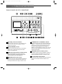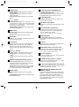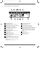
1
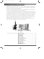
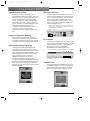
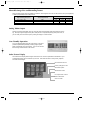
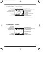
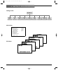
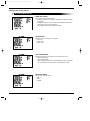
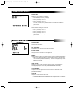
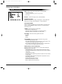
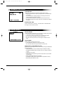
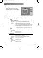
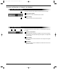
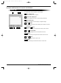
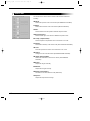
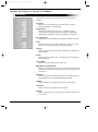
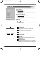
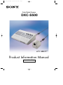
DXC_S500_cover.qxd
02.10.21 2:23 PM
Page 3
Color Digital Camera
DXC-S500
iCY SHOT T M
Product Information Manual
Internal Use Only
DXC_S500_1C.qxd
02.10.21 2:17 PM
Page 2
DXC_S500_1C.qxd
02.10.21 2:17 PM
Page 3
1. INTRODUCTION
As the number of microscopy applications increases, the method of capturing images has changed from using
NTSC/PAL-based video signals to the simplicity and convenience of PC-based image data. A flexible interface
with PCs along with superior picture quality are now essential to microscopy, and the Sony DXC-S500 Digital
Camera System meets these demands by providing both.
Comprising two separate units, the DXC-S500 includes a compact and lightweight camera head unit (CHU)
and a camera control unit (CCU) with an integrated 3.5 type LCD monitor.
The 2/3 type five mega-pixel CCD incorporated in the CHU provides ultra-high-resolution images and precise
color reproduction. The LCD on the CCU enables you to monitor live images and offers user-friendly operation.
The added advantage of the DXC-S500 is its flexible interface with PCs. An IEEE 1394 interface on the CCU
allows uncompressed image data transfer to a PC. A built-in PCMCIA card slot enables you to store images on
various media, such as "Memory Stick™", CompactFlash™, SmartMedia™ and removable hard disk drives.
What's more, a hot-plug function allows the camera to be effortlessly connected to a PC, while the supplied
TWAIN driver supports various application software such as Photoshop® and Image-Pro® Plus.
With excellent picture quality, sophisticated features and PC-friendly operation, the Sony DXC-S500 is the
ideal system to support your medical and scientific microscopy applications.
C O N T E N T S
1. INTRODUCTION . . . . . . . . . . . . . . . . . . . . . . . . . . . . . . . . . . . . . . 3
2. PRODUCT CONCEPT . . . . . . . . . . . . . . . . . . . . . . . . . . . . . . . . . . 4
3. APPLICATIONS . . . . . . . . . . . . . . . . . . . . . . . . . . . . . . . . . . . . . . . 4
4. KEY FEATURES . . . . . . . . . . . . . . . . . . . . . . . . . . . . . . . . . . . . . . . . 5
5. PANEL LAYOUT . . . . . . . . . . . . . . . . . . . . . . . . . . . . . . . . . . . . . . . 8
6. MENU FUNCTION . . . . . . . . . . . . . . . . . . . . . . . . . . . . . . . . . . . . 12
7. TWAIN DRIVER SOFTWARE . . . . . . . . . . . . . . . . . . . . . . . . . . . . . 17
8. SYSTEM EXAMPLE . . . . . . . . . . . . . . . . . . . . . . . . . . . . . . . . . . . . 23
9. OPTIONAL ACCESSORIES . . . . . . . . . . . . . . . . . . . . . . . . . . . . . . 23
10. SPECIFICATIONS . . . . . . . . . . . . . . . . . . . . . . . . . . . . . . . . . . . . . 24
11. PIN ASSIGNMENT . . . . . . . . . . . . . . . . . . . . . . . . . . . . . . . . . . . . 25
12. DIMENSIONS . . . . . . . . . . . . . . . . . . . . . . . . . . . . . . . . . . . . . . . . 26
13. TECHNICAL APPENDIX . . . . . . . . . . . . . . . . . . . . . . . . . . . . . . . . 26
DXC-S500 Product Information Manual –
3
DXC_S500_1C.qxd
02.10.21 2:17 PM
Page 4
2. PRODUCT CONCEPT
Ultra-high-resolution Color Digital Camera for Microscopy
■ Superb picture quality with a 2/3 type five mega-pixel CCD
■ Flexible interface with PCs
◆ IEEE 1394 interface
◆ PC card slot
◆ TWAIN driver
■ User-friendly operation with an integrated 3.5 type LCD monitor
■ C-mount system
3. APPLICATIONS
Bio-medical Microscopy
■ Microbiology
■ Pathology
■ Genetics
4 – DXC-S500 Product Information Manual
DXC_S500_1C.qxd
02.10.21 2:17 PM
Page 5
4. KEY FEATURES
Superb Picture Quality
By utilizing several core technologies, the
DXC-S500 offers superb picture quality. With a five
mega-pixel 2/3 type IT CCD, the DXC-S500 can
capture ultra-high-resolution and high-precision
images. The maximum number of pixels used for
image capture is 2560 (H) x 1920 (V), providing
superior resolution. The use of RGB primary color
mosaic filters contributes to precise color
reproduction, while a cooling device cools the
CCD chip to 5 ˚C (at 0 to 35 ˚C ambient
temperature) to achieve excellent signal-to-noise
ratio.
IEEE 1394 Interface
The IEEE 1394 (400 Mb/s) interface located on the
camera control unit enables direct interface with various PCs or IEEE 1394 boards*. The interface supports a hot-plug function for quick access to the
camera's image without restarting the PC. The pictures are transmitted in uncompressed IEEE 1394
format for highest accuracy.
* When Microsoft® Windows® is used, IEEE 1394 boards conforming to OHCI are supported. For Macintosh®, genuine
FireWire® boards are supported.
Long-term Exposure Shooting
Built-in frame memory provides a remarkable
enhancement in sensitivity by allowing the charge
accumulation period of the CCD (typically 1/60 second) to be extended to a maximum of 60 seconds.
Fluorescence Image Capturing
The DXC-S500 provides a fluorescent mode
(FL MODE), which facilitates focus and capture
adjustments for dark objects at the touch of a button.
When activated, it automatically boosts the camera
gain level and lowers the frame rate so the dark
object can be clearly seen. When focus
adjustments have been made, pressing
the "CAPTURE" button resets the gain and
calculates the appropriate shutter speed (Long-term
Exposure) so a clear image can be obtained. And,
thanks to the CCD cooling device, the dark noise
that is typically seen in Long-term Exposure mode is
dramatically reduced.
PC Card Slot
A PC card slot is located on the front of the CCU for
storing images directly onto various media. This slot
supports PCMCIA ATA Type II*, enabling data storage in a "Memory Stick", CompactFlash,
SmartMedia and removable hard disk drive.
* PC cards supporting 3.3 V power supply only are not available.
TWAIN Driver
The supplied TWAIN driver enables the use of various application software. You can use this driver to
monitor live images on the PC application window,
and to capture images with a simple mouse click.
DXC-S500 Product Information Manual –
5
DXC_S500_1C.qxd
02.10.21 2:17 PM
Page 6
Selectable Image Size and Recording Format
Three recording image sizes are available for selection, and images of each size can be stored in TIFF (uncompressed)
or JPEG (compressed, three modes) format.
Image recording size (H x V)
FULL: 2560 x 1920
TIFF (uncompressed)
15 MB
JPEG (compressed)
High
5 MB
Mid
Low
2.5 MB
1.3 MB
SXGA: 1280 x 960
3.8 MB
1.3 MB
630 KB
310 KB
VGA: 640 x 480
940 KB
310 KB
160 KB
78 KB
The above image data sizes are approximations.
Analog Video Output
Analog composite output (BNC) and Y/C output (S-Video) terminals allow high-frame-rate live monitoring. The output signal supports VGA (640 x 480) size at a 30 fps (NTSC)/25 fps (PAL) frame rate, so
you can easily focus the microscope by viewing the image on a video monitor.
User-Friendly Operation
A 3.5 type 200,000-pixels LPS TFT LCD monitor on the CCU
provides sophisticated operability, including image capture,
index picture display and menu setting. You can also monitor
the live image with the built-in LCD monitor.
Index Picture Display
The Index Picture Display allows images stored on the PC card to be previewed as thumbnails. Up to
10 thumbnail images can be viewed at any one time. This allows the user to easily check, playback,
and erase stored images.
Recorded date and time
Picture quality/picture size
Gain/shutter speed
White balance mode
EV compensation volume/
flash mode/rotation
User ID number
6 – DXC-S500 Product Information Manual
DXC_S500_1C.qxd
02.10.21 2:17 PM
Page 7
AE Functions
The AE (Auto Exposure) function automatically
detects the lighting conditions or brightness of the
object and adjusts the shutter speed and gain for
proper exposure. The DXC-S500 is equipped with a
number of AE modes that offer superb image quality.
C-Mount System
To provide an extensive choice of lenses, the
DXC-S500 uses the 2/3 type C-mount system for
flexible and easy lens mounting.
Foot Switch
An optional FS-20 foot switch is available, enabling
you to capture and record images by simply stepping on the switch.
User File (max. three files)
A variety of customized data can be saved as a user
file, up to three of which can be stored in the CCU.
By loading this user file, you can quickly recreate
particular setup conditions.
Black & White Mode
The image output can be selected from either Color
or Black & White modes.
Interval Recording (max. 24 hours)
It is possible to record at pre-determined intervals
(up to 24 hours).
Picture Rotation (0˚/180˚ selectable)
This function rotates the image by 0˚ to 180˚.
Histogram Display
The DXC-S500 automatically detects the luminance
distribution of images, displaying a histogram on the
monitor so you can verify the condition of each
exposure.
2x Digital Zoom
DXC-S500 Product Information Manual –
7
DXC_S500_1C.qxd
02.10.21 2:17 PM
Page 8
5. PANEL LAYOUT
Camera Control Unit (CCU) Control Panel
MENU
EXIT
CAM GAIN
RED
AE LOCK
AE MODE
WHITE
MANUAL
ENTER
KEY
LOCK
DISP/INFO EZ FOCUS/INDEX HISTOGRAM
PLAY
SHUTTER
ERASE
LIVE
AUTO
BLUE
WB MODE
MANUAL
EV COMP
CAPTURE
GAIN
FL MODE
REC
PC CARD
1 On/standby switch and indicator
When the power of the unit is on, the indicator is lit in
green, and when the unit is in standby mode the
indicator is lit in orange.
2 GAIN (BLUE/RED) controls
Adjusts the red and blue gain levels in manual white
balance mode, or after executing the Auto White
Balance mode (WB-AUTO).
3
WHITE (white balance) button and AUTO indicator
When the WB MODE is set to AUTO (the AUTO
indicator is lit in green), pressing the WHITE button
activates WB-AUTO (Auto White Balance).
4 CAM GAIN (camera gain) control
In MANUAL exposure mode (the MANUAL indicator is
lit in red), turning the CAM GAIN volume adjusts the
camera gain level within the range of 0 dB to 12 dB.
8 – DXC-S500 Product Information Manual
5 AE MODE button and MANUAL indicator
Sets the exposure mode of the camera to AE-AUTO or
MANUAL. In AE-AUTO mode, the electronic shutter
speed and the camera gain automatically change in
accordance with the brightness of the subject. In
MANUAL mode (the MANUAL indicator is lit in red), the
electronic shutter speed and the camera gain can be
adjusted independently.
6 SHUTTER (electronic shutter) control
In MANUAL exposure mode (the MANUAL indicator is
lit in red), turning the SHUTTER volume controls the
shutter speed within the range of 1/10,000 s to 60 s.
7 AE LOCK button and indicator
In AE-AUTO mode, pressing the AE LOCK button fixes
the exposure time (the AE LOCK indicator is lit in
green).
DXC_S500_1C.qxd
02.10.21 2:17 PM
Page 9
8 ENTER button
In MENU DISPLAY mode: Displays the next layer of
the menu system.
In INDEX DISPLAY mode: Displays the selected
image in full screen.
In Camera LIVE mode: Initializes the focus indicator
display.
9 ↑/↓/←/→ buttons
In MENU DISPLAY mode: The ↑ (cursor up) or ↓ (cursor down) button moves the cursor in the menu display
up or down. The ← (data down) or → (data up) button
sets the data in the menu display.
In INDEX DISPLAY mode: Selects an image from the
thumbnail images displayed.
10 MENU button
In Camera LIVE mode: Displays the MAIN MENU on
the LCD monitor.
In PLAY mode: Displays the menu for replay.
11 EXIT button
When the menu is displayed, pressing the EXIT button
restores the previous menu.
12 LCD monitor
Displays the picture being shot, a captured image, or a
playback image from a PC card. Also displays the
menu, the list of still images (INDEX DISPLAY), or
information such as shutter speed, file name, and picture size.
13 PLAY /+/_ buttons
button: Replays a still image recorded on a card.
+ button: Replays the still image of the next file
number.
_
button: Replays the still image of the previous file
number.
14 DISP/INFO (display/information) button
In Camera LIVE mode: Displays information on the
camera's live image such as white balance mode, EV
compensation volume, and shutter speed.
In PLAY mode: Displays information about the image
recorded to a PC card, such as record date and time,
EV compensation volume, and shutter speed.
15 ERASE button
In PLAY mode: Erases the files on the loaded PC
card.
In INDEX DISPLAY mode: Erases the selected image
from thumbnail images.
16 EZ FOCUS (easy focus)/INDEX button
In Camera LIVE mode: Activates 2x electronic zoom
to facilitate focusing operations.
In PLAY mode: Displays thumbnail images of still pictures (INDEX DISPLAY) recorded to a PC card.
17 HISTOGRAM button
In Camera LIVE mode: Displays a histogram of the
image on the LCD monitor.
18 LIVE button and indicator
Activates the Camera LIVE mode (the indicator is lit in
green).
19 KEY LOCK button and indicator
Pressing the KEY LOCK button for more than two
seconds (the indicator is lit in green) disables the
operation of buttons and volumes.
* The KEY LOCK mode retains while the unit is switched off.
20 CAPTURE button
In Camera LIVE mode: Pressing the CAPTURE
button stores a picture in the built-in frame memory of
the camera.
21 Card slot
Accepts a PC card or a Memory Stick installed in the
MSAC-PC2 Memory Stick adaptor.
22 CARD EJECT button and access lamp
Pressing this button ejects the loaded PC card. The
access lamp is lit in red during reading or writing.
* Do not eject the card while the access lamp is lit.
23 REC (record) button
Records a still image to a PC card. The access lamp
is lit in red during recording.
_
24 EV COMP (compensation) +/ buttons
In AE-AUTO or FL MODE, pressing the + or _ button
adjusts the exposure compensation.
25 FL (fluorescent) MODE button and indicator
Activates the fluorescent mode of the camera. When
activated, the indicator is lit in green.
26 WB (white balance) MODE button and
MANUAL indicator
Sets the White Balance adjustment mode to AUTO or
MANUAL. In WB-AUTO mode, pressing the WHITE
button automatically adjusts the white balance. In
WB-MANUAL mode (the MANUAL indicator is lit in
red), the white balance is adjusted manually with the
GAIN RED/BLUE volumes.
DXC-S500 Product Information Manual –
9
DXC_S500_1C.qxd
02.10.21 2:17 PM
Page 10
Camera Control Unit (CCU) Rear Panel
NTSC
CAMERA
OFF
ON
PAL
VIDEO
FLASH
S VIDEO
~ AC IN
OUTPUT
IEEE
1394
FS2
FS1
REMOTE
1 O/I (main power) switch
Switches the main power of the camera on or off.
2 S-VIDEO OUTPUT connector (mini DIN 4-pin)
Outputs an S-VIDEO (Y/C video) signal.
3 VIDEO OUTPUT connector (BNC-type)
Outputs a composite video signal.
4 NTSC/PAL select switch
Selects the output video signal from NTSC or PAL.
5 FLASH connector
Connects the cable of a flash lamp.
6 CAMERA connector (10-pin)
Connects to the CAMERA connector on the CHU using
the supplied camera cable.
7 IEEE 1394 (digital interface) connector * (6-pin)
Connects to a computer via an IEEE 1394 cable (not
supplied).
* This connector cannot be used for connection to camera equipment
with a DV connector.
* This connector is not compatible with bus power.
10 – DXC-S500 Product Information Manual
TRIG IN
8 FS2 connector (D-sub 9-pin)
Reserved for future use.
9 FS1 connector (stereo mini jack)
Connects to the optional FS-20 foot switch.
10 TRIG IN (trigger input) connector (BNC-type)
Used when an external device, such as a slave unit,
generates the trigger signal. When using a flash lamp
in INPUT mode, connects a slave unit to the TRIG IN
connector.
11 ~AC IN socket
Connects to the AC power cord.
12 Ventilation opening
DXC_S500_1C.qxd
02.10.21 2:17 PM
Page 11
LCD Monitor Display
Camera LIVE Mode
Flash indicator
Current date and time
LIVE mode
Number of recorded pictures on a card*
Picture size/picture quality
White balance mode
Focus area (AE window)
EV compensation volume
Focus indicator
Folder name*
Remaining shot number on a card
File name*
Shutter speed
User ID number
ISO sensitivity/camera gain
* Displayed only when a card is inserted.
LCD Monitor Display
PLAY Mode
Flash indicator
Protect indicator
PLAY (playback) mode
White balance mode
Recorded date and time
Number of recorded pictures on a card
Picture size/picture quality
EV compensation volume
Folder name
File name
User ID number
Shutter speed
ISO sensitivity/camera gain
DXC-S500 Product Information Manual –
11
DXC_S500_1C.qxd
02.10.21 2:18 PM
Page 12
6. MENU FUNCTION
Configuration
Main Menu
Sensitivity
mode
Picture
size
File format
mode
AE detect
mode
User file
set up
System
set up
Camera
set up
Main Menu
<<MAIN MENU>>
SENSITIVITY MODE :
PICTURE SIZE :
FILE FORMAT MODE :
JPEG QUALITY :
AE DETECT MODE :
USER FILE SET UP
SYSTEM SET UP
CAMERA SET UP
CAPTURE/REC SET UP
ISO100
2560x1920
JPEG
MIDDLE
MID
<<PLAY SET UP>>
PROTECT MODE
DELETE MODE
DISPLAY SET
<<CAPTURE/REC
SET UP>>
CAPTURE TRIG :
MAIN SW
↓↑SELECT ←
→ SET
Sub Menu
INTERVAL
<<CAMERA
SET REC
UP>>TIME
B&W
OFF
ROTATE :
0 [↑]
SHARPNESS
LEVEL :00
<<SYSTEM
SET UP>>
←
→
DATE & TIME AUTO-WHITE-PAINT OFF
PC CARD INIT GAMMA : ON
AE SPEED : NORMAL
ID FILE
SET MODE
<<USER
SET UP>>
FLASH MODE : OFF
BEEP
:ON
DATA LOAD
DISPLAY SET :
KEY
CLICK
:ON
DATA SAVE
OSD COLOR :
WHITE
[ENTER] NEXT [EXIT] BACK
COLOR BARSESELECT
:OFF
LCD SET
↓↑SELECT [ENTER] NEXT
12 – DXC-S500 Product Information Manual
[EXIT] BACK
Capture/rec
set up
Play
set up
DXC_S500_1C.qxd
02.10.21 2:18 PM
Page 13
Setting Items in the Menu
Recording Mode Menus
SENSITIVITY MODE:
<<MAIN MENU>>
SENSITIVITY MODE :
ISO100
PICTURE SIZE :
2560x1920
FILE FORMAT MODE :
JPEG
JPEG QUALITY :
AE DETECT MODE :
MIDDLE
MID
USER FILE SET UP
SYSTEM SET UP
CAMERA SET UP
CAPTURE/REC SET UP
Sets the gain used for image capture.
• In AE-AUTO mode, the sensitivity is selectable from ISO100, ISO200,
and ISO400.
• In MANUAL exposure mode, the gain value adjusted with the CAM
GAIN volume on the CCU is displayed.
• In FL MODE, the fluorescent mode is activated.
↓↑SELECT ←
→ SET
PICTURE SIZE:
<<MAIN MENU>>
SENSITIVITY MODE :
ISO100
PICTURE SIZE :
2560x1920
FILE FORMAT MODE :
JPEG
JPEG QUALITY :
AE DETECT MODE :
MIDDLE
MID
USER FILE SET UP
Selects the size of the image to be captured.
• 640 x 480
• 1280 x 960
• 2560 x 1920
SYSTEM SET UP
CAMERA SET UP
CAPTURE/REC SET UP
↓↑SELECT ←
→ SET
FILE FORMAT MODE:
<<MAIN MENU>>
SENSITIVITY MODE :
ISO100
PICTURE SIZE :
2560x1920
FILE FORMAT MODE :
JPEG
JPEG QUALITY :
AE DETECT MODE :
MIDDLE
MID
USER FILE SET UP
SYSTEM SET UP
CAMERA SET UP
Selects the file format of an image to be recorded to a PC card.
• JPEG (compressed)
• TIFF (uncompressed)
When JPEG is selected as the FILE FORMAT, the data compression
ratio is selectable from three modes _ LOW, MIDDLE, or HIGH.
CAPTURE/REC SET UP
↓↑SELECT ←
→ SET
AE DETECT MODE:
<<MAIN MENU>>
SENSITIVITY MODE :
ISO100
PICTURE SIZE :
2560x1920
FILE FORMAT MODE :
JPEG
JPEG QUALITY :
AE DETECT MODE :
USER FILE SET UP
MIDDLE
MID
Sets the size of the AE window.
• SPOT
• MID
• LARGE
SYSTEM SET UP
CAMERA SET UP
CAPTURE/REC SET UP
↓↑SELECT ←
→ SET
DXC-S500 Product Information Manual –
13
DXC_S500_1C.qxd
02.10.21 2:18 PM
Page 14
USER FILE SET UP Menu
DATA LOAD:
<<USER FILE SET UP>>
DATA LOAD
DATA SAVE
↓↑SELECT [ENTER] NEXT [EXIT] BACK
Selects the user setting to be loaded.
• No.0 (RESET): the factory settings
• No.1 (yy.mm.dd): user file 1
• No.2 (yy.mm.dd): user file 2
• No.3 (yy.mm.dd): user file 3
The year, month, and day that the data was saved are indicated in
parentheses.
DATA SAVE:
Saves the user setting as a user file.
• No.1 (yy.mm.dd): user file 1
• No.2 (yy.mm.dd): user file 2
• No.3 (yy.mm.dd): user file 3
The year, month, and day that the data is to be saved are indicated in
parentheses.
SYSTEM SET UP Menu
<<SYSTEM SET UP>>
DATE & TIME
PC CARD INIT
ID SET MODE
BEEP
KEY CLICK
OSD COLOR
COLOR BARS
LCD SET
↓↑SELECT
DATE & TIME:
Sets the date and time.
:ON
:ON
:WHITE
:OFF
← SET
→
PC CARD INIT:
Initializes the PC card to be used with the camera.
ID SET MODE:
Assigns a user ID number up to 20 digits long.
BEEP:
Selects whether a beep is sounded during operation (ON/OFF selectable).
• KEY CLICK: Selects whether to sound a beep when an operation button is pressed (ON/OFF selectable). This item is displayed only when
BEEP is set to ON.
OSD COLOR:
Selects the color of the characters used for menus, information, and
messages displayed on the LCD (WHITE/BLUE/RED selectable).
COLOR BARS:
Outputs a color bar signal to the LCD monitor or an external monitor
(ON/OFF selectable).
LCD SET:
Adjusts the LCD monitor of the CCU.
• CONTRAST/BRIGHT/COLOR/BACKLIGHT adjustments are available.
14 – DXC-S500 Product Information Manual
DXC_S500_1C.qxd
02.10.21 2:18 PM
Page 15
Setting Items in the Menu
CAMERA SET UP Menu
<<CAMERA SET UP>>
B&W
OFF
ROTATE :
0 [↑]
SHARPNESS LEVEL :
±00
AUTO-WHITE-PAINT
OFF
GAMMA :
ON
AE SPEED :
NORMAL
FLASH MODE :
OFF
DISPLAY SET :
↓↑SELECT [ENTER] NEXT
[EXIT] BACK
B&W*: Displays the Camera LIVE picture in black and white.
• ON: Black and white
*When B&W is selected, the image will also be captured in B&W.
• OFF: Color
ROTATE: Rotates the image by 180˚ (0˚/180˚selectable).
SHARPNESS LEVEL:
Adjusts the sharpness of an image. Pressing the ← button softens the
sharpness of an image, while pressing the → button sharpens it.
AUTO-WHITE-PAINT:
Allows an offset to be added to the auto white balance convergent point
using the GAIN RED/BLUE volumes on the CCU. This offset can be
turned ON or OFF.
GAMMA: Selects the gamma compensation.
• OFF: Gamma compensation off.
• ON (MS): Gamma compensation for microscope shooting.
• ON (STD): Gamma compensation for a CRT monitor.
AE SPEED: Selects the focusing speed in AE mode.
• NORMAL
• FAST
• SLOW
FLASH MODE: Selects the shooting mode when using a flash.
• OFF: Deactivates the flash mode.
• EXT: INPUT: Selected when using a slave unit. The flash lamp is synchronized with the trigger signal from a slave unit.
• EXT: OUTPUT: Selected when using a flash lamp. The flash lamp is
synchronized with the trigger signal from the CCU.
DISPLAY SET (in Camera LIVE mode):
Selects the items that are displayed on the monitor when pressing the
DISP/INFO button on the CCU.
• SIZE/FORMAT/QLTY (Picture size/recording format/picture quality).
• FOLDER/FILE NAME (Folder name/file name of an image recorded to
a PC card).
• ID NO (User ID number).
• REMAINING SHOT (Remaining number of shots that can be recorded
to a PC card).
• TV/GAIN/EV COMP (Shutter speed/gain/EV compensation volume).
• AE FRAME (AE window).
• FOCUS DISPLAY (Focus indicator).
• WB WHITE (White Balance mode).
• DATE & TIME (Current date and time).
DXC-S500 Product Information Manual –
15
DXC_S500_1C.qxd
02.10.21 2:18 PM
Page 16
CAPTURE/REC SET UP Menu
<<CAPTURE/REC SET UP>>
CAPTURE TRIG :
MAIN SW
INTERVAL REC TIME
↓↑SELECT ←
→ SET
[EXIT] BACK
CAPTURE TRIG:
Selects the input connector to be used for image capture control.
• MAIN SW: Selected when capturing images with the CAPTURE button
on the CCU.
• FS1: Selected when capturing images by switching the FS-20 foot
switch connected to the FS1 connector.
• FS2: Selected to activate the input signal from the FS2 connector.
• EXT TRIG: Selected when using a slave unit connected to the TRIG IN
connector.
INTERVAL REC TIME:
Sets an interval time for recording. The interval time is selectable within
the range of 10 seconds to 24 hours.
PLAY SET UP Menu
<<PLAY SET UP>>
PROTECT MODE
DELETE MODE
DISPLAY SET
↓↑SELECT [ENTER] NEXT [EXIT] BACK
PROTECT MODE:
Protects the images recorded on a PC card from accidentally being erased.
• 1 SHOT ON: Protects the image being played.
• 1 SHOT OFF: Removes protection from the image being played.
• ALL ON: Protects all images recorded on the PC card.
• ALL OFF: Removes protection from all images recorded on the PC
card.
DELETE MODE:
Deletes images recorded on the PC card.
• 1 SHOT DELETE: Deletes the image being played.
• ALL DELETE: Deletes all images recorded on the PC card.
DISPLAY SET (in CAPTURE/PLAY mode):
Selects items to be displayed on the monitor when pressing the DISP/INFO
button on the CCU.
• SIZE/FORMAT/QLTY (Picture size/recording format/picture quality).
• FOLDER/FILE NAME (Folder name/file name of an image recorded on
a card).
• ID NO (User ID number).
• REMAINING SHOT (Remaining number of shots that can be recorded
on a PC card).
• DATE & TIME (Date and time of recording).
• TV/GAIN/EV COMP (Shutter speed/gain/EV compensation volume).
• WB MODE (White Balance mode).
16 – DXC-S500 Product Information Manual
DXC_S500_1C.qxd
02.10.21 2:18 PM
Page 17
7. TWAIN DRIVER SOFTWARE
By opening the supplied TWAIN driver software from
your application software (e.g., Photoshop or ImagePro Plus), images stored on the camera can be
transmitted to a computer in uncompressed IEEE 1394
format. You can also operate basic functions and alter
settings of the camera from the computer.
* The supplied TWAIN driver software can only be used with the Sony
DXC-S500 color digital camera.
System Requirements for the Supplied TWAIN Driver Software
For Microsoft Windows users
Hardware
IBM PC/AT®-compatible machine
CPU:
Intel® Pentium® III or faster (Pentium III 400 MHz or faster recommended)
Memory capacity:
128 MB RAM minimum (more than 256 MB RAM recommended)
Cache memory:
256 KB minimum
Hard disk:
50 MB memory or greater required
PCI slot:
One free PCI slot required (PCI 2.1-compliant)
Video board:
24-bit full-color video board supporting DirectX V8.0 or later required.
To display images correctly with this software, the video board requires the ability
to show at least 16,000,000 colors. To display live images correctly, the video
board requires a high-performance video chip supporting DirectX, such as ATI
RADEON 7500/8500 series or NVIDIA GeForce 2/3/4 series.
*The TWAIN driver software displays the live image using the function of the high-performance video board through the DirectX V8.0. Correct operation of the software is not
guaranteed with some notebook computers in which the video board cannot be changed.
Software
Supporting OS:
Windows 98SE/ME/2000 Professional SP2/XP Home/XP Professional
DirectX:
DirectX Runtime module V8.0 or later
Application software
supporting TWAIN
driver:
Photoshop V5.0 or later
Image-Pro Plus V4.5 or later
For Macintosh users
Hardware
Apple Computer, Inc. genuine personal computer
CPU:
PowerPC G3/G4
PowerMac, PowerBook, iMac, iBook series
Memory capacity:
128 MB RAM minimum (more than 256 MB RAM recommended)
Hard disk:
50 MB memory or greater required
FireWire port:
One free built-in FireWire port required
Software
Supporting OS:
Mac OS 8.6, 9.0, 9.1, 9.2
QuickTime:
QuickTime V4.0 or later
Application software
supporting TWAIN
driver:
Photoshop V5.0 or later
DXC-S500 Product Information Manual –
17
DXC_S500_1C.qxd
02.10.21 2:18 PM
Page 18
Locations and Functions of Controls (for Windows)
Image Information Panel
1
The Image Information Panel displays information about the images.
1 Shot number display
Displays the number of shots taken by the camera.
2 Status display
2
Displays the status of the DXC-S500 camera.
Image Control Panel
1
2
3
The Image Control Panel contains buttons for transmitting the image from
the camera.
1 Acquire (to PC) button
Clicking this button transmits the images from the CCU into the application software. The transmitted image then appears in the application
software window.
2 Cancel button
Clicking this button cancels transmission of the image into the application software.
3 Quit button
Clicking this button exits the TWAIN driver software and returns to the
application software.
18 – DXC-S500 Product Information Manual
DXC_S500_1C.qxd
02.10.23 4:10 PM
Page 19
Locations and Functions of Controls (for Windows)
Capture Tab
1
2
3
The Capture tab is used to capture or record images.
1 Device display area
Shows the device name recognized.
2 Progress bar display area
Shows the progress bar when an image is being transferring.
3 Image display area
Shows a live image, the index display or a playback image.
4 LIVE L button
Selects the Camera LIVE mode to display the live image on the LCD
or video monitor.
4
5
6
7
8
9
5 CAPTURE C button
Captures a still image in the built-in frame memory of the camera.
6 REC R (record) button
Records a still image to the PC card inserted in the CCU.
7
– button
Selects a still image of the previous file number on the PC card.
8 PLAY P button
Plays a still image stored on the PC card.
9
+ button
Selects a still image of the next file number on the PC card.
DXC-S500 Product Information Manual –
19
DXC_S500_1C.qxd
02.10.21 2:18 PM
Page 20
Camera Tab
The Camera tab is used to set the camera modes and the functions for
recording.
AE Mode:
Selects the exposure mode of the camera (AUTO/MANUAL selectable).
FL Mode:
Selects the fluorescent mode of the camera (ON/OFF selectable).
Shutter:
Sets the electronic shutter speed in MANUAL exposure mode.
CAM (camera) Gain:
Sets the master gain of the camera in MANUAL exposure mode.
EV Comp. (compensation):
Sets the exposure compensation value in AE-AUTO or FL mode.
Sensitivity:
Sets the ISO sensitivity in AE-AUTO mode (ISO 100/200/400 selectable).
AE Lock:
Fixes the exposure time ON or OFF in AE-AUTO or FL mode.
AE Detect:
Changes the size of the AE window (SPOT/MID/LARGE selectable).
WB (white balance) Mode:
Selects the white balance mode of the camera (AUTO/MANUAL
selectable).
RED Gain:
Adjusts the red gain manually.
BLUE Gain:
Adjusts the blue gain manually.
WHITE One Push button:
Activates the auto white balance mode (WB AUTO).
Sharpness:
Adjusts the sharpness of the image.
20 – DXC-S500 Product Information Manual
DXC_S500_1C.qxd
02.10.21 2:18 PM
Page 21
Locations and Functions of Controls (for Windows)
System Tab
The System tab is used to set the camera modes and the functions for
recording.
Image Size:
Selects the size of the image to be recorded to the PC card (640 x
480/1280 x 960/2560 x 1920 selectable).
Image Quality:
Selects the recording format of the image _ selectable from TIFF
(uncompressed), JPEG High (JPEG low compression), JPEG Middle
(JPEG middle compression), or JPEG Low (JPEG high compression).
E.Z. (easy) Focus:
Activates E.Z. Focus to facilitate focus operations in Camera LIVE mode.
Flash:
Selects the Flash mode when using a flash lamp or a slave unit _ selectable from OFF, ON (EXT: OUTPUT), and ON (EXT: INPUT).
Gamma:
Selects the gamma compensation mode _ selectable from ON (MS), ON
(STD), and OFF.
Rotate:
Rotates the camera image by 180˚ _ selectable from 0˚(normal image) or
180˚ (upside down).
Interval REC:
Selects the interval-recording mode to ON or OFF.
B&W (Black and White) mode:
Switches the Camera LIVE image from color to black and white. When ON
is selected, both the Camera LIVE image and the captured image become
monochrome.
OSD Color:
Selects the color of the characters used for menus, information, and messages displayed on the LCD (WHITE/BLUE/RED selectable).
ID Mode:
Selects whether or not to assign a user ID number to each image.
Histogram:
Displays a histogram on the LCD monitor of the CCU.
Display:
Displays information such as menus and focus indicator on the LCD monitor of the CCU.
DXC-S500 Product Information Manual –
21
DXC_S500_1C.qxd
02.10.21 2:18 PM
Page 22
Timer & ID Tab
The Timer & ID tab is used to set the clock and ID number for the camera.
System Date & Time:
Displays the date and time.
Set Date & Time button
After the date and time are set in the boxes, clicking this button transfers
the values to the camera.
Interval Rec (recording) Time:
Sets the interval recording time for the camera..
Set Interval Rec Time button
After the interval recording time is set in the box, clicking this button transfers the value to the camera.
ID No. Input:
Assigns a user ID number of up to 20 digits.
Set ID No. button
After the user ID number is set in the box, clicking this button transfers the
ID number to the camera.
Locations and Functions of Controls (for Macintosh)
1
1 Image display area
Shows a live image, the index display, or a playback image.
2 LIVE button
Shows the live image on the LCD or video monitor.
3 Capture button
Captures a still image in the built-in frame memory of the camera.
2
3
4
5
6
4 Rec (record) button
Records a still image on the PC card inserted into the CCU.
5 Cancel button
Clicking this button cancels the transmission of the image into the
application software.
6 Acquire (to PC) button
Clicking this button transmits the images from the CCU into the application software. The transmitted image then appears in the application
software window.
22 – DXC-S500 Product Information Manual
DXC_S500_1C.qxd
02.10.21 2:18 PM
Page 23
8. SYSTEM EXAMPLE
Monitor
FS-20
Foot Switch
VBS/S-Video
PC
IEEE 1394
Camera cable (5 m)
DXC-S500
Microscope
Adaptor
MSAC-PC2
PC Card Adaptor
Coupler
Memory Stick
Microscope
9. OPTIONAL ACCESSORIES
FS-20 Foot Switch
MSA-8A/16A/32A/64A/128A Memory Stick
MSAC-PC2 Memory Stick Adaptor
VMC-IL6615A/IL6635A IEEE 1394 cable (6-pin to 6-pin)
DXC-S500 Product Information Manual –
23
DXC_S500_1C.qxd
02.10.21 2:18 PM
Page 24
10. SPECIFICATIONS
Imager
Pick-up device
2/3 type IT (Interline Transfer) CCD, interlaced scan
Color filter
R, G, B primary color filter
Total picture elements (H x V)
5.24 mega-pixels (2658 x 1970)
Recording pixel elements (H x V)
2560 x 1920
Sensing area (H x V)
9.74 x 7.69 mm, square pixels
Camera
Lens mount
C-mount
Flange back
17.526 mm in air
CCD cooling
Cooled to 5 °C (41 °F) at 0 °C to 35 °C (32 °F to 95 °F) ambient temperature
Bit depth
10-bit ADC
Sensitivity
ISO 100/200/400 selectable
Gain
Auto (AGC): 0 dB/6 dB/12 dB selectable
Manual: 0 to 12 dB (1 steps)
Exposure control
AE: Auto/Manual selectable, AE lock function
AE area
Spot/Mid/Large
AE level
Variable
AE speed
Fast/Mid/Slow
Shutter speed
Auto/Manual (60 to 1/10000 s)/Electrical shutter
Gamma
ON (MS)/ON (STD)/OFF *1 switchable
White balance
Auto/Manual (R/B gain)
Detail level
Variable
EV compensation
-2 to 2 EV (0.25 EV steps)
Flash
Ext: Input mode/Output mode
User file
1/2/3 switchable (3 pattern memories)
Electrical zoom
2x (VGA size)
Fluorescent mode
ON/OFF
Black & White mode
ON/OFF
Interval recording
ON/OFF Max. 24 hours
User ID
ON/OFF Max. 20 digits
Picture rotate
0°/180° selectable
Live picture
Image size (H x V)
640 x 480 pixels
Frame rate
30 fps/25 fps
Display
Digital interface and analog video output
Size
3.5 type
Type
TFT color LCD made of low-temperature polysilicon
Resolution
200000 dots
Frame rate
NTSC: 30 fps, PAL: 25 fps
Image display
Live image or recording image (VGA size)
LCD
*1: MS: for Microscopy, STD: for Standard
24 – DXC-S500 Product Information Manual
DXC_S500_1C.qxd
02.10.28 3:45 PM
Page 25
Recording system
Recording media
PC card-type removable HDD (PCMCIA-ATA Type II), Max. 5 GB
Memory Stick (PC card adaptor required), Max. 128 MB
CompactFlash (PC card adaptor required), Max. 330 MB
SmartMedia (PC card adaptor required), Max. 128 MB
Max. recording pixel number (H x V)
2560 x 1920
Image data size (H x V)
3 modes: 2560 x 1920, 1280 x 960, 640 x 480
Recording format
TIFF (uncompressed), JPEG (compressed, three modes)
Software
TWAIN driver
Bundled, for Windows/Macintosh
Supported OS
Windows 98SE/ME/2000/XP, Mac OS 8.6/9.0/9.1/9.2
Supported application software
Image-Pro Plus version 4.5 or later (for Windows)
Photoshop version 5.0 or later (for Windows/Macintosh)
Control from PCs
Data transmission, live picture display, camera control
Output signals
IEEE 1394 (400 Mb/s), UYUV 16 bit/s
VBS: 1.0 Vp-p, 75 Ω, sync negative
Y: 1.0 Vp-p, 75 Ω
C: NTSC 0.284 Vp-p, 75 Ω (without sync)
PAL 0.3 Vp-p, 75 Ω (without sync)
General
Operating temperature
-5 °C to 45 °C (23 °F to 113 °F)
Storage temperature
-20 °C to 60 °C (-4 °F to 140 °F)
Power requirements
100 to 240 V AC, 50/60 Hz
Power consumption
Max. 24 W
Dimensions (W x H x D)
CHU: 56 x 72 x 72 mm (2 1/4 x 2 7/8 x 2 7/8 inches)
CCU: 270 x 163 x 79 mm (10 3/4 x 6 1/2 x 3 1/6 inches)
Mass
CHU: 300 g (11 oz)
Connectors
IEEE 1394 output (6-pin jack)*2
Video output (BNC)
External trigger in (BNC)
FS1 (stereo mini jack)
AC in
PC card (PCMCIE-ATA type II)
S-Video output (Mini DIN 4-pin)
Flash out (X)
FS2 (D-sub 9-pin)
Camera cable (10-pin)
TWAIN driver software (CD-ROM)
Camera cable
User's guide for TWAIN driver software
Lens mount cap
Operation manual
CCU: 1.8 kg (3 lb 15 oz)
Supplied accessories
*2: IEEE 1394: Bus power not supported
11. PIN ASSIGNMENT
5
4
9
3
8
2
7
1
6
1
2
3
4
5
6
7
8
9
FOOT SW1
FOOT SW2
FOOT SW3
NC
NC
GND
NC
NC
NC
DXC-S500 Product Information Manual –
25
DXC_S500_1C.qxd
02.10.21 5:35 PM
Page 26
12. DIMENSIONS
Camera Head Unit (CHU)
Camera Control Unit (CCU)
79 (3
56 (6 1/2)
1/6
1/2
)
)
162
(6
72 (2 7/8)
163 (6 1/2)
163 (6 1/2)
270 (10 3/4)
72 (2 7/8)
7/1
6)
79 (3 1/6)
35 (1
Unit : mm (inches)
13. TECHNICAL APPENDIX
What's TWAIN?
TWAIN is an open, industry-standard interface that directly
acquires image data from devices such as scanners and
digital cameras, without closing the application software.
The Elements of TWAIN
TWAIN defines a standard software protocol and API
(application programming interface) for communication
between the application software and the image-acquisition
device (the source of the data).
The three key elements of TWAIN are:
• The application software _ The application must be
modified to use TWAIN.
• The Source Manager software _ This software manages
the communication between the application software and
the source. The source code is provided in the TWAIN
Developer's Toolkit.
• The Source software _ This software controls the imageacquisition device and is programmed by the device
developer to comply with TWAIN specifications.
26 – DXC-S500 Product Information Manual
HW Dependant I/O Layer
(SCSI, Parallel, Serial, etc.)
Data Source
Software
Application
Software
Image
Application
Source Manager
Software
Digital Camera
Data Source
Fax
Application
Data
Source
Manager
Scanner
Data Source
Word
Proccessor
Application
TWAIN
interface
Consumers of
Image Data
Image Databace
Data Source
Producers of
Image Data
Sony Custom TWAIN Driver
TWAIN Elements
Target Device DXC-S500
DXC_S500_1C.qxd
02.10.21 2:18 PM
Page 27
DXC-S500 Product Information Manual –
27
DXC_S500_cover.qxd
02.10.21 2:23 PM
Page 2
© 2002 Sony Corporation. All rights reserved.
Reproduction in whole or in part without written permission is prohibited.
Design, features and specifications are subject to change without notice.
All non-metric weights and measures are approximate.
Sony, iCY-SHOT and Memory Stick are trademarks of Sony Corporation.
All other trademarks are the property of their respective owners.
MK10001V1IW02OCT
Printed in Japan on recycled paper.