1
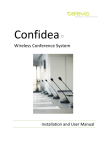
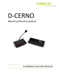
Confidea
Wired Conference System
Installation and User Manual
Confidea Wired System
Installation and User Manual
Table of Contents
Table of Contents ..........................................................................................................................2
Section 1 – General Information.....................................................................................................7
1.
Copyright Statement.......................................................................................................9
2.
Trademarks .................................................................................................................. 10
3.
Safety Instructions........................................................................................................ 11
3.1.
3.2.
Important safety instructions........................................................................................ 11
Power Connections....................................................................................................... 14
4.
Confidea System Information........................................................................................ 15
Section 2 – System Components .................................................................................................. 16
5.
Table Top Contribution units......................................................................................... 17
5.1.
5.1.1.
Introduction ................................................................................................................. 17
The delegate units. ........................................................................................................ 17
5.2.
5.3.
5.4.
5.5.
5.5.1.
5.5.2.
Functionality overview.................................................................................................. 18
Controls and indicators ................................................................................................. 18
Installation ................................................................................................................... 25
Maintenance ................................................................................................................ 25
General......................................................................................................................... 25
Cleaning........................................................................................................................ 25
5.6.
5.6.1.
5.6.2.
5.6.3.
5.6.4.
5.6.5.
Microphones ................................................................................................................ 26
Introduction.................................................................................................................. 26
Electrical and acoustic properties .................................................................................. 26
Microphone connector .................................................................................................. 26
Operation ..................................................................................................................... 27
Installation and handling............................................................................................... 27
6.
Flushmount Contribution units...................................................................................... 28
6.1.
6.2.
6.3.
6.4.
6.4.1.
Introduction ................................................................................................................. 28
Controls and indicators ................................................................................................. 28
Installation ................................................................................................................... 33
Maintenance ................................................................................................................ 38
General......................................................................................................................... 38
Televic Conference Systems
2011-11-14
2
Confidea Wired System
6.4.2.
Installation and User Manual
Cleaning........................................................................................................................ 38
7.
Interpreter desk............................................................................................................ 39
7.1.
7.2.
7.3.
7.3.1.
7.3.2.
Introduction ................................................................................................................. 39
Controls and indicators ................................................................................................. 39
Maintenance ................................................................................................................ 41
General......................................................................................................................... 41
Cleaning........................................................................................................................ 41
8.
Central Control unit ...................................................................................................... 42
8.1.
8.2.
8.3.
8.4.
8.5.
8.5.1.
8.5.2.
8.5.3.
8.5.4.
8.5.5.
Introduction ................................................................................................................. 42
Control and indicators................................................................................................... 42
Additional Licenses ....................................................................................................... 45
Installation ................................................................................................................... 45
External connections..................................................................................................... 45
Power Supply ................................................................................................................ 45
XLR IN Connection......................................................................................................... 45
XLR OUT Connection...................................................................................................... 45
Sub D 15 OUT connection .............................................................................................. 46
RS232 Connection ......................................................................................................... 46
8.6.
8.7.
Repeater for the system................................................................................................ 48
Menu structure............................................................................................................. 49
9.
Analog Output Panel..................................................................................................... 75
9.1.
9.2.
9.3.
9.4.
9.5.
Introduction ................................................................................................................. 75
Controls and indicators ................................................................................................. 75
Installation ................................................................................................................... 77
Configuration ............................................................................................................... 77
Remote Control ............................................................................................................ 79
10.
System cables............................................................................................................... 80
11.
Software Suite .............................................................................................................. 80
Section 3 – System Design............................................................................................................ 83
12.
Conference network setup............................................................................................ 84
12.1.
12.1.1.
12.1.2.
12.1.3.
Interconnecting units.................................................................................................... 84
Confidea wired.............................................................................................................. 84
Flushmount panels ........................................................................................................ 84
Interpreter unit ............................................................................................................. 84
Televic Conference Systems
2011-11-14
3
Confidea Wired System
Installation and User Manual
12.2.
Connection to the central unit....................................................................................... 85
12.2.1. General setup ............................................................................................................... 85
12.2.2. Dual branch Redundancy ............................................................................................... 86
12.3.
Connecting the PC to the central unit ............................................................................ 87
12.3.1. Examples of connections ............................................................................................... 88
12.3.2. Confidea coupled (wired + wireless) ............................................................................... 90
90
12.4.
Master slave configuration............................................................................................ 91
12.5.
Additional equipment for the conference system .......................................................... 92
12.5.1. Powering the Confidea Cu.............................................................................................. 92
Section 4 – The Menu explained................................................................................................... 93
13.
Root Menu .......................................................................... Error! Bookmark not defined.
14.
Conference menu ......................................................................................................... 95
14.1.
Initialization ................................................................................................................. 95
14.1.1. Automatic init ............................................................................................................... 95
14.1.2. Manual init ................................................................................................................... 95
14.2.
14.3.
14.4.
14.5.
14.6.
14.7.
14.8.
Operating Mode ........................................................................................................... 95
Microphone Limit ......................................................................................................... 96
Loudspeaker................................................................................................................. 96
Microphones ................................................................................................................ 97
Chairman...................................................................................................................... 97
Reset............................................................................................................................ 98
Options ........................................................................................................................ 98
15.
Interpretation menu ..................................................................................................... 99
15.1.
15.2.
15.3.
15.4.
15.5.
Configuration ............................................................................................................... 99
Booth Configuration ..................................................................................................... 99
Initialization ............................................................................................................... 100
Reset.......................................................................................................................... 101
Options ...................................................................................................................... 101
16.
Auxiliary Menu ........................................................................................................... 103
16.1.
16.2.
16.3.
16.4.
Outputs ...................................................................................................................... 103
Inputs......................................................................................................................... 103
Remote Conferencing ................................................................................................. 103
External Equalizer ....................................................................................................... 104
Televic Conference Systems
2011-11-14
4
Confidea Wired System
Installation and User Manual
17.
System Menu.............................................................................................................. 105
17.1.
17.2.
17.3.
17.4.
17.5.
Diagnostics ................................................................................................................. 105
Camera Control........................................................................................................... 105
Control Panel.............................................................................................................. 105
Ambient Sound........................................................................................................... 105
Version....................................................................................................................... 105
18.
Language Menu .......................................................................................................... 105
19.
License Menu ............................................................................................................. 105
Section 5 – Appendix ................................................................................................................. 107
20.
Default Settings .......................................................................................................... 109
21.
Camera Control Protocol ............................................................................................. 112
21.1.
21.2.
21.3.
Communication .......................................................................................................... 112
Commands ................................................................................................................. 112
Examples.................................................................................................................... 113
22.
Control Panel Protocol ................................................................................................ 114
22.1.
22.2.
22.3.
Communication .......................................................................................................... 114
Commands ................................................................................................................. 114
Examples.................................................................................................................... 116
Televic Conference Systems
2011-11-14
5
Confidea Wired System
Installation and User Manual
Section 1 – General Information
Televic Conference Systems
2011-11-14
7
Confidea Wired System
1.
Installation and User Manual
Copyright Statement
No part of this publication or documentation
accompanying this product may be reproduced in
any form or by any means or used to make any
derivative such as translation, transformation, or
adaptation without the prior written permission of
the publisher, except in case of brief quotations
embodied in critical articles or reviews. Contents are
subject to change without prior notice.
Copyright© 2011 by Televic Conference NV. All rights
reserved.
The authors of this manual have made every effort in
the preparation of this book to ensure the accuracy
of the information. However, the information in this
manual is supplied without warranty, either express
or implied. Neither the authors, Televic Conference
NV, nor its dealers or distributors will be held liable
for any damages caused or alleged to be caused
either directly or indirectly by this book.
Televic Conference Systems
2011-11-14
9
Confidea Wired System
2.
Installation and User Manual
Trademarks
All terms mentioned in this manual that are known
to be trademarks or service marks have been
appropriately capitalized. Televic Conference NV
cannot attest to the accuracy of this information. Use
of a term in this book should not be regarded as
affecting the validity of any trademark or service
mark.
Televic Conference Systems
2011-11-14
10
Confidea Wired System
3.
Installation and User Manual
Safety Instructions
The Confidea Conference system is state of the art
and has been designed to meet quality.
Nevertheless, the individual components of the
conference system can cause danger for persons and
material assets if
Slots and openings in the cabinet are provided for
ventilation and to ensure reliable operation of the
product and to protect it from overheating. These
openings must not be blocked or covered. The
openings should never be blocked by placing the
product on a bed, sofa, rug, or other similar surface.
This product should not be placed in a built-in
installation such as a bookcase or rack unless proper
ventilation is provided or the manufacturer's
the conference system is not used as intended,
the conference system is set up by personnel not
familiar with the safety regulations,
6.
the conference system is converted or altered
incorrectly,
The product should be situated away from heat
sources such as radiators, heat registers, stoves, or
other products (including amplifiers) that produce
The safety instructions are not observed.
heat.
instructions have been adhered to.
7.
Heat
Attachments
3.1. Important safety
instructions
Do not use attachments not recommended by the
product manufacturer as they may cause hazards.
1.
Do not use this product near water or in a moistures
environment - for example, near a bath tub, wash
bowl, kitchen sink, or laundry tub; in a wet
basement; or near a swimming pool, in an
Read Instructions
All the safety and operating instructions should be
read before the product is operated.
1.
Retain Instructions
8.
Water and Moisture
unprotected outdoor installation; and the like.
The safety and operating instructions should be
9.
retained for future reference.
Only use attachments/accessories specified by the
manufacturer. Do not place this product on an
unstable cart, stand, tripod, bracket, or table. The
product may fall, causing serious injury to a child or
adult and serious damage to the product. Use only
with a cart, stand, tripod, bracket, or table
recommended by the manufacturer, or sold with the
product. Any mounting of the product should follow
the manufacturer's instructions, and should use a
mounting accessory recommended by the
2.
Heed Warnings
All warnings on the product and the operating
instructions should be adhered to.
3.
Follow Instructions
All instructions for installation or operating / use
should be followed.
4.
Cleaning
Unplug this product from the wall outlet before
cleaning. Do not use liquid cleaners or aerosol
cleaners. Use a damp cloth for cleaning.
5.
Accessories
manufacturer.
10. Moving
A product and cart combination should be moved
with care. Quick stops, excessive force, and uneven
Ventilation
Televic Conference Systems
2011-11-14
11
Confidea Wired System
Installation and User Manual
surfaces may cause the product and cart
15. Lightning
combination to overturn.
11. Power Sources
This product should be operated only from the type
of power source indicated on the marking label. If
you are not sure of the type of power supply to your
home, consult your product dealer or local power
company. For products intended to operate from
battery power, or other sources, refer to the
operating instructions.
For added protection for this product during a
lightning storm, or when it is left unattended and
unused for long periods of time, unplug it from the
wall outlet. This will prevent damage to the product
due to lightning and power-line surges.
Not applicable when special functions are to be
maintained, such as evacuation systems
16. Overloading
Do not overload wall outlets, extension cords or
integral convenience receptacles as this can result in
12. Power Lines
An outdoor system should not be located in the
vicinity of overhead power lines or other electric light
or power circuits, or where it can fall into such power
lines or circuits. When installing an outdoor system,
extreme care should be taken to keep from touching
such power lines or circuits, as contact with them
might be fatal. U.S.A. models only - refer to the
National Electrical Code Article 820 regarding
a risk of fire or electric shock.
17. Object and Liquid Entry
Never push objects of any kind into this product
through openings as they may touch dangerous
voltage points or short-out parts that could result in
a fire or electric shock. Never spill liquid of any kind
on the product.
installation of CATV systems.
18. Inflammable and Explosive Substance
13. Grounding or Polarization
Do not defeat the safety purpose of the polarized or
ground-type plug. A polarized plug has two blades
with one wider than the other. A grounding type plug
has two blades and a third grounding prong. The
wider blade or the third prong are provided for your
safety. If the provided plug does not fit into the
outlet, consult an electrician for replacement of the
Avoid using this product where there are gases, and
also where there are inflammable and explosive
substances in the immediate vicinity.
19. Heavy Shock or Vibration
When carrying this product around, do not subject
the product to heavy shock or vibration.
obsolete outlet.
20. Servicing
14. Power-Cord Protection
Do not attempt to service this product yourself as
opening or removing covers may expose you to
dangerous voltage or other hazards. Refer all
servicing to qualified service personnel.
Power-supply cords should be routed to that they
are not likely to be walked on or pinched by items
placed upon or against them, paying particular
attention to cords at plug, convenience receptacles,
and the point where they exit from the product.
Televic Conference Systems
2011-11-14
12
Confidea Wired System
Installation and User Manual
21. Damage Requiring Service
24. Coax Grounding
Unplug this product from the wall outlet and refer
servicing to qualified service personnel under the
If an outside cable system is connected to the
apparatus, be sure the cable system is grounded.
U.S.A. models only: Section 810 of the National
Electrical Code, ANSI/NFPA No.70-1981, provides
information with respect to proper grounding of the
mount and supporting structure, grounding of the
coax to a discharge apparatus, size of grounding
conductors, location of discharge unit, connection to
grounding electrodes, and requirements for the
following conditions:
a.
When the power-supply cord or plug is
damaged.
b.
If liquid has been spilled, or objects
have fallen into the product.
c.
If the product has been exposed to rain
grounding electrode.
or water.
d.
If the product does not operate
normally by following the operating
instructions. Adjust only those controls
that are covered by the operating
instructions as an improper adjustment
of other controls may result in damage
and will often require extensive work by
a qualified technician to restore the
product to its normal operation.
e.
If the product has been dropped or
damaged in any way.
f.
When the product exhibits a distinct
change in performance-this indicates a
need for service.
22. Replacement Parts
When replacement parts are required, be sure the
service technician has used replacement parts
specified by the manufacturer or have the same
characteristics as the original part. Unauthorized
substitutions may result in fire, electric shock, or
other hazards.
23. Safety Check
Upon completion of any service or repairs to this
product, ask the service technician to perform safety
checks to determine that the product is in proper
operating condition.
Televic Conference Systems
2011-11-14
13
Confidea Wired System
Installation and User Manual
3.2. Power Connections
Warning:
For permanently connected equipment, a readily
accessible disconnect device shall be incorporated in
the fixed wiring; for pluggable equipment, the
socket-outlet shall be installed near the equipment
and shall be easily accessible.
To reduce the risk of fire or electric
shock, do not expose this appliance to
rain or moisture. Do not open the
cabinet; refer servicing to qualified
personnel only.
Warning:
To prevent electric shock, do not use
this (polarized) plug with an extension
cord receptacle or other outlet unl ess
the blades can be fully inserted to
prevent blade exposure.
This label may appear on the bottom of the
Attention:
apparatus due to space limitations.
Installation should be performed by
qualified service personnel only in
accordance with the National Electrical
The lightning flash with an
arrowhead symbol, with an
equilateral triangle, is intended to
alert the user to the presence of
un-insulated ‘dangerous voltage’
within the products enclosure that may be of
sufficient magnitude to constitute a risk of electric
Code or applicable local codes.
Attention:
The exclamation mark within an
equilateral triangle is intended to
alert the user to the presence of
important operating and
maintenance (servicing)
instructions in the literature accompanying the
Equipment with or without ON/OFF
switches have power supplied to the
equipment whenever the power cord is
inserted into the power source;
however, the equipment is operational
only when the ON/OFF switch is in the
ON position. The power cord is the
main power disconnect for all
appliance.
equipment.
shock to persons.
Televic Conference Systems
2011-11-14
14
Confidea Wired System
4.
Installation and User Manual
Confidea System
Information
This manual describes the wired part of the Confidea
range:
Confidea CU : Central control unit
Confidea –L : Mobile Table top unit
Integrated flushmount panels
Interpreter desks
The central unit serves small to medium sized
conference rooms and offers a wide range of
connectivity to integrate with other audiovisual
equipment.
The system can work in a standalone mode or with
additional software suite for enhanced setup and
control.
The central unit also provides an extended set of
commands to integrate other AV solutions as e.g.
camera control systems, room management systems,
recording systems, …
In terms of contribution units Confidea offers a wide
range of products to serve applications going from
discussion over voting to simultaneous
interpretation, this as a table top or flush mount
solution.
The wireless Confidea product range is described in a
separate manual. However this manual describes
how to connect the Confidea wireless range to the
Confidea central control unit.
Televic Conference Systems
2011-11-14
15
Confidea Wired System
Installation and User Manual
Section 2 – System Components
Televic Conference Systems
2011-11-14
16
Confidea Wired System
5.
Installation and User Manual
an Oled display. All the different delegate units will
Table Top
Contribution units
be presented in the next chapter.
5.1. Introduction
The contribution units consist of Delegate and
Chairman units. Both are used for speech
reinforcement in a conference room. The
chairman units are used to guide and control an
ongoing discussion.
The units are connected in series. One cable branch
can comprise up to 20 conference units. The 6 ports
at the back of the central unit can each connect a
branch of delegate units. Up to 120 delegate units
can thus be connected to one central unit. And up to
1024 delegate units can be set up through coupled
central units.
All the different delegate units will be presented in
the next chapter.
The units can be divided into three categories:
Discussion :
Confidea L-DD (Figure 5.1), L-CD(Figure 5.2),
L-2D2D (Figure 5.3: Confidea L-2D2D)
Voting:
Confidea L-DV (Figure 5.4), L-CV (Figure 5.5)
Interpretation :
Confidea L-DI (Figure 5.6), L-CI (Figure 5.7), L2D2I (Figure 5.8) , L-DIV (Figure 5.9), L-CIV
(Figure 5.10)
5.1.1. The delegate units.
The delegate units feature a built-in loudspeaker,
allowing the participant to directly hear all audio
information, e.g. speeches, presentations or any
other audio material. This loudspeaker system
ensures excellent sound quality at a comfortable
volume throughout the entire conference room.
The delegate unit’s electret microphone transmits
every word in excellent audio quality over the
system. The red signal ring on the microphone serves
as an indicator of who is currently occupying the
floor (when the red light is on).
In configurations with voting units, the conference
participants can participate in voting sessions.
The delegate units can range from the most basic
units to delegate units intended for a chairman with
options like voting, interpreter channel selection and
Televic Conference Systems
2011-11-14
17
Confidea Wired System
Installation and User Manual
5.2. Functionality overview
5.3. Controls and
indicators
The Confidea units have the following features:
1.
2.
3.
4.
Microphone connector:
Connection of a microphone to the wireless unit.
Microphone button:
Activation/deactivation of the microphone.
Indication LEDs show the status of the
microphone. (red : active, green : request)
Loudspeaker:
Distributes the floor channel. Mutes in case
microphone is active.
Headphone connectors:
Connection of headphone to the wireless unit.
Mono- and stereo headphones can be used.
Televic Conference Systems
5.
Volume buttons:
Change the volume level of the headphones.
6.
Voting buttons:
Each voting button has a blue LED indicator.
7.
Information display:
Indication of voting, volume and channel
information.
8.
Channel selection buttons:
Changes the audio channel sent to the
headphones. Each button has a blue indication
LED. Pressing these buttons affects the
information display.
9.
Voting control buttons:
Used by the chairman to control a voting
session. (start / pause / stop)
10. PRIOR button:
Short press : temporarily deactivates the
microphone of all active units.
Long press : permanently deactivates the
microphone of all active units.
11. Next button:
Grants the floor to the next delegate in the
waiting list.
12. System volume control:
Adjust system volume by holding the button and
pressing the volume buttons.
13. Microphone status LEDs
14. RJ45 bus connections
Due to the auto port sensing there is no
dedicated IN and OUT port.
2011-11-14
18
Confidea Wired System
Installation and User Manual
Figure 5.1: Confidea L-DD
Figure 5.2: Confidea L-CD
Televic Conference Systems
2011-11-14
19
Confidea Wired System
Installation and User Manual
Figure 5.3: Confidea L-2D2D
Figure 5.4: Confidea L-DV
Televic Conference Systems
2011-11-14
20
Confidea Wired System
Installation and User Manual
Figure 5.5: Confidea L-CV
Figure 5.6: Confidea L-DI
Televic Conference Systems
2011-11-14
21
Confidea Wired System
Installation and User Manual
Figure 5.7: Confidea L-CI
Figure 5.8: Confidea L-2D2I
Televic Conference Systems
2011-11-14
22
Confidea Wired System
Installation and User Manual
Figure 5.9: Confidea L-DIV
Figure 5.10: Confidea L-CIV
Televic Conference Systems
2011-11-14
23
Confidea Wired System
Installation and User Manual
Figure 5.11: RJ45 connections
Televic Conference Systems
2011-11-14
24
Confidea Wired System
Installation and User Manual
5.4. Installation
5.5. Maintenance
In order to use the Confidea units, the microphone
need to be installed.
5.5.1. General
For instructions, see the microphone installation
Caution:
Make sure that the units are not positioned too close
to each other. It is recommended to keep a min.
distance of 1m between the units to prevent
Do not put any objects on top of the
units. Object falling through the holes of
the unit can cause damage.
howling.
The recommended speaking distance for people to
speak to the microphone is between 20 to 40 cm.
Caution:
Do not install the units in a location near
heat sources as radiators, air ducts. or
direct sunlight.
Caution:
Make sure the units are not exposed to
excessive dust, humidity, mechanical
vibration or shock.
5.5.2. Cleaning
Caution:
Do not use alcohol, ammonia or
petroleum solvents or abrasive cleaners
to clean the units.
To keep its original condition it is advised to
periodically clean the unit:
Televic Conference Systems
2011-11-14
Use a clean soft cloth that is not fully moist.
Make sure the device is completely dry
before usage.
25
Confidea Wired System
Installation and User Manual
5.6.3. Microphone connector
5.6. Microphones
Figure 5.4: Connector pin layout (bottom view)
5.6.1. Introduction
The Confidea-MIC38SL (38 cm) pluggable
microphone is used with the different delegate- and
chairman units. This microphone has a unidirectional
response for optimum performance even in noisy
conditions, and has a very low susceptibility to RFinterference from mobile phones.
5.6.2. Electrical and
acoustic properties
Table 5.1: Microphone characteristics
pin 1 : microphone GND
pin 2 : microphone signal
pin 3 : unused
Transducer type
Ba ck electret (condenser)
pin 4 : LED +
Operating principle
Pres s ure gra dient
pin 5 : LED -
Polar pattern
Uni -directional,
ca rdi oïd
Frequency response
50 Hz – 16000 Hz
Nominal impedance
1kOhm (at 1 kHz, drop resistance =
1k2, Vdd = 3.3VDC )
Load impedance
> 5kOhm
Max.SPL at 1 kHz
120 dB SPL
Equivalent sound
pressure level
< 25 dB(A)
Free field sensitivity
7mV/Pa , +/- 3 dB a t 1 kHz or
(-43dB, 0dB=1V/Pa a t 1kHz)
Power supply
3.3V DC, 0.5 mA
Consumption
0.5 mA (without LED ring);
ma x. 25 mA (with illuminated ring)
Televic Conference Systems
2011-11-14
26
Confidea Wired System
Installation and User Manual
5.6.4. Operation
The color of the microphone indicator ring shows the
status of the microphone (refer to Table 5.2: LED ring
The microphone contains the following elements
(refer to Figure 5.5):
status).
1.
Indicator ring: shows the status of the
microphone
2.
Union nut: attaches the pluggable microphone
to the unit
3.
Microphone plug: connects the microphone to
the unit
Table 5.2: LED ring status
Color
Condition
Red (on)
Mi crophone active
Red (flash)
La s t mi nute of speech time (if set
vi a s oftware)
or
Speech request (if set vi a s oftware)
Figure 5.5: Microphone
5.6.5. Installation
and handling
The pluggable microphone has a screw connection.
For mounting, plug and fasten the microphone into
the unit.
Caution:
Do not force the microphone screw
thread while mounting the microphone
on the unit.
This can cause permanent damage to
the microphone and receptacle
connector on the Confidea unit.
Televic Conference Systems
2011-11-14
27
Confidea Wired System
Installation and User Manual
5.
Volume buttons:
Change the volume level of the headphones.
6.
Voting buttons:
Each voting button has a blue LED indicator.
6.1. Introduction
7.
Information display:
Indication of volume and channel information.
In case the conference equipment needs to be built
into a table, the integrated panels are a great
solution.
8.
Channel selection buttons:
Changes the audio channel sent to the
headphones. Pressing these buttons affects the
information display.
9.
PRIOR button:
Short press: temporarily deactivates the
microphone of all active units.
Long press: permanently deactivates the
microphone of all active units.
6.
Flushmount
Contribution units
There are several models serving different
applications:
Discussion :
FD/M (Figure 6.1 : FD/M)
FC/M (Figure 6.2 :FC/M)
Voting + Badge:
FD/MV5B (Figure 6.3 : FD/MV5B)
FC/MV5B (Figure 6.4 : FC/MV5B)
Interpretation + Voting:
FD/MV5CS (Figure 6.5 : FD/MV5CS)
FC/MV5CS (Figure 6.6 : FC/MV5CS)
10. Next button:
Grants the floor to the next delegate in the
waiting list.
11. Microphone request status LED
12. Microphone status LED
13. Chip card inserted status LED
6.2. Controls and
indicators
14. Chip card slot
15. RJ45 bus connections
Dedicated IN and OUT port!
The integrated flush mount uni ts have the following
features:
1.
Microphone:
Fixed interference free microphone of 38 cm.
2.
Microphone button:
Activation/deactivation of the microphone.
Indication LEDs show the status of the
microphone. (red : active, green : request)
3.
Loudspeaker:
Distributes the floor channel. Mutes in case
microphone is active.
4.
Headphone connectors:
Connection of headphone to the wireless unit.
Mono- and stereo headphones can be used.
Televic Conference Systems
2011-11-14
28
Confidea Wired System
Installation and User Manual
Figure 6.1 : FD/M
Figure 6.2 :FC/M
Televic Conference Systems
2011-11-14
29
Confidea Wired System
Installation and User Manual
Figure 6.3 : FD/MV5B
Figure 6.4 : FC/MV5B
Televic Conference Systems
2011-11-14
30
Confidea Wired System
Installation and User Manual
Figure 6.5 : FD/MV5CS
Figure 6.6 : FC/MV5CS
Televic Conference Systems
2011-11-14
31
Confidea Wired System
Installation and User Manual
Figure 6.7 : FD/MV5BCS
Figure 6.8 : FC/MV5BCS
Televic Conference Systems
2011-11-14
32
Confidea Wired System
Installation and User Manual
6.3. Installation
The integrated panels are flush mount panels and
need to be integrated in conference furniture.
The cut-out of the different models can be found
below.
FD/M and FC/M
Error! Not a valid bookmark self-reference.
FD/MV5B and FC/MV5B
Figure 6.10 : Dimensions and cut-out FD/MV5B and
FC/MV5B
FD/MV5CS and FC/MV5CS
Figure 6.11 : Dimensions and cut-out FD/MV5CS and
FC/MV5CS
FD/MV5BCS and FC/MV5BCS
Figure 6.12 : Dimensions and cut-out FD/MV5BCS
and FC/MV5BCS
Make sure to enter the panels straight into the cutout of the table.
Televic Conference Systems
2011-11-14
33
Confidea Wired System
Installation and User Manual
Figure 6.9 : Dimensions and cut-out FD/M and FC/M
Televic Conference Systems
2011-11-14
34
Confidea Wired System
Installation and User Manual
Figure 6.10 : Dimensions and cut-out FD/MV5B and FC/MV5B
Televic Conference Systems
2011-11-14
35
Confidea Wired System
Installation and User Manual
Figure 6.11 : Dimensions and cut-out FD/MV5CS and FC/MV5CS
Televic Conference Systems
2011-11-14
36
Confidea Wired System
Installation and User Manual
Figure 6.12 : Dimensions and cut-out FD/MV5BCS and FC/MV5BCS
Televic Conference Systems
2011-11-14
37
Confidea Wired System
Installation and User Manual
6.4. Maintenance
6.4.1. General
Caution:
Do not put any objects on top of the
units. Object falling through the holes of
the unit can cause damage.
Caution:
Do not install the units in a location near
heat sources as radiators, air ducts. or
direct sunlight.
Caution:
Make sure the units are not exposed to
excessive dust, humidity, mechanical
vibration or shock.
6.4.2. Cleaning
Caution:
Do not use alcohol, ammonia or
petroleum solvents or abrasive cleaners
to clean the units.
To keep its original condition it is advised to
periodically clean the unit:
Use a clean soft cloth that is not fully moist.
Make sure the device is completely dry
before usage.
Televic Conference Systems
2011-11-14
38
Confidea Wired System
7.
Installation and User Manual
Interpreter desk
7.1. Introduction
In cases where interpretation is required one or
several interpreter desks will be required in the
system.
The interpreter unit has a different design as a
delegate unit. Next to the quality microphone and
the headphone output it has three knobs for
adjusting the volume, treble and bass levels of the
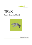
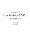
3.
Headphone connection, 3,5mm jack
4.
Loudspeaker
5.
Badge reader
6.
Badge LED
7.
A channel button
8.
B channel button
9.
Message button
10. Mute button
11. Red signal ring
12. Microphone
incoming speech.
The badge can contain all relevant information for
each interpreter so that each interpreter can transfer
his settings to a new interpreter unit.
An extended amount of functionality is made
available on the interpreter unit by the easy to use
interface knobs and buttons and the LCD display.
Every aspect of this functionality will be explained in
the next chapter.
13. Relay button 3
14. Microphone on LED
15. Microphone button
16. Relay button 2
17. Request to speak LED
18. Relay button 1
19. Loudspeaker channel
20. Menu buttons
7.2. Controls and
indicators
The interpreter desks have the following features:
21. Autofloor LED
22. Loudspeaker volume control
23. Headphone audio level control
24. Headphone connection, 3,5mm jack
25. Microphone connection for headset, 3,5mm jack
1.
IN connector
2.
OUT connector
Televic Conference Systems
2011-11-14
39
Confidea Wired System
Installation and User Manual
1
2
24
3
4
23
22
5
21
6
7
20
8
19
9
MIC
10
11
18
17
16
12
15
14
13
2
25
1
Televic Conference Systems
2011-11-14
40
Confidea Wired System
Installation and User Manual
7.3. Maintenance
7.3.1. General
Caution:
Do not put any objects on top of the
units. Object falling through the holes of
the unit can cause damage.
Caution:
Do not install the units in a location near
heat sources as radiators, air ducts. or
direct sunlight.
Caution:
Make sure the units are not exposed to
excessive dust, humidity, mechanical
vibration or shock.
7.3.2. Cleaning
Caution:
Do not use alcohol, ammonia or
petroleum solvents or abrasive cleaners
to clean the units.
To keep its original condition it is advised to
periodically clean the unit:
Use a clean soft cloth that is not fully moist.
Make sure the device is completely dry
before usage.
Televic Conference Systems
2011-11-14
41
Confidea Wired System
8.
Installation and User Manual
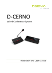
10. XLR 3M balanced output (AUX OUT)
Central Control unit
8.1. Introduction
The Confidea CU is the heart of the system. It
controls all delegate units and can interconnect to
other systems either via the external audio
connections or control ports (camera control, control
panel)
In case a larger number of units are required the
systems can be extended with multiple control units
in a master/slave configuration. The maximum
number of units is 1024.
The central control units can be used for any type of
application, from discussion over voting to
simultaneous interpretation. The control unit
supports 4 languages as a standard, but can go up to
28 languages via additional licenses (Floor + 8, Floor
+ 28).
8.2. Control and indicators
1.
LCD display
2.
F1 menu button
3.
F2 menu button
4.
F3 menu button
5.
Scroll wheel
6.
EXIT menu button
7.
ENTER menu button
8.
XLR 3F balanced input (AUX IN1)
9.
XLR 3F balanced input (AUX IN2)
Televic Conference Systems
12. RJ-45 shielded connectors (SLAVE IN) for a
connection with a master central unit when the
central unit is a slave in a coupled environment.
13. RJ-45 shielded connectors (SLAVE OUT) for a
connection with a slave central unit when the
central unit is already a slave in coupled
environment or to connect conference units
with an external power supply.
The system has a built in power supply to drive 120
units and can operate in a standalone mode.
Initialization and configuration can be done via the
integrated menu. Optionally, this can also be done
via additional software suite.
The control unit has the following features:
11. RJ-45 shielded connector (MASTER OUT) for a
connection with a slave central unit when the
central unit is master in a coupled environment
or to connect conference units with an external
power supply.
14. RJ45 DATA OUT connector:
Connection to optional AOP2500 output panel
15. SUBD15 output connector:
6 unbalanced controllable audio outputs to be
used to connect to recording equipment,
language distribution, …
16. COM 1 serial communications port to connect a
PC. When connected with a PC, all the data
related with the interpreter system flows over
this connection. The COM port operates at a
speed of 19200 bits per second.
17. COM2 serial communication port:
Connection to camera control system (refer to
Camera Control Protocol ) or control panel (refer
to Control Panel Protocol )
18. COM 3 serial communication port:
Control of a PC with microphone, delegate,
voting management software.
19. Port 1-6:
Digital bus connection to connect contribution
units and interpreter desks.
20. Power supply fan
21. Mains plug connector
22. Power switch
23. Fuse holder
2011-11-14
42
Confidea Wired System
Installation and User Manual
24. Headphone connection, 3.5 mm jack socket. The
audio signal of the headphone connection is
directly associated with the AUX OUT 6 port.
Every change in the configuration of the AUX
OUT 6 port will be noticeable on the headphone
connection
1
2
3
4
5
6
7
EXIT
F1
F2
F3
ENTER
24
23
T 3.15 A L ( 230 V)
T 7 A L ( 115 V)
COM 1
COM 2
I
AUX OUT 1
AUX IN 2
AUX IN 1
1
9
1
1
1
AUX OUT 2 :
2
10
2
2
2
AUX OUT 3 :
3
11
3
3
3
AUX OUT 4 :
4
12
5
13
: 6
14
AUX OUT 5 :
AUX OUT 6
0
22
AUX OUT / CONTROL
AUX OUT 1 :
WARNING
COM 3
ELECTRICAL
HAZARD.
AUTHORIZED
PERSONNEL ONLY.
PORT 6
8
CONTROL OUT : 7 ( ) 15 (c)
CONTROL IN 1 : 8 ( MAX+5V )
PORT 5
PORT 4
PORT 3
PORT 2
PORT 1
DATA
OUT
SLAVE
OUT
SLAVE
IN
9
MASTER
OUT
115 - 230 V
7 - 3.5 A
50 / 60 Hz
10
21
20
Televic Conference Systems
19
18
2011-11-14
17
16
15
14
13
12
11
43
Confidea Wired System
Installation and User Manual
A complete technical overview of the settings of the
serial communication ports COM1, COM2 and COM3:
transmit the audio signal of the floor as “original
soundtrack” to a broadcasting station.
The CONFIDEA CU is able to serve conference
systems in a non-coupled environment with up to
120 units. For larger systems with a maximum of
1024 terminals, up to 40 central units can be
interconnect via system cables. The CONFIDEA CU is
an integration of a microphone system and an
It is also possible to connect an infrared language
distribution system to the CONFIDEA CU, allowing
guests or participants who don’t have their own
conference unit to follow the conference via infrared
headphones. The guests or participants can also
choose between the floor channel and up to 28
interpreter system.
additional language channels.
The CONFIDEA CU’s menu control allows to:
An analog output panel ( AOP) can also be connected
to the CONFIDEA CU. The purpose of the analog
output panel is to provide the system with additional
analog outputs. A total of 9 XLR-3M ports are
available to send an analog signal out to other
devices, for example, a recording device or a public
address system.
-
set the conference system to one of the 10
different operating modes (note however
that some are only relevant in an
environment where there is a PC connected
to the central unit with the microphone
management software),
set the delegate unit’s audio options like volume,
automatic gain reduction, low, middle and treble,
configure the options of the microphone system
and the interpreter system,
initialize the microphone and interpreter system,
specify the auxiliary IN/OUT settings,
reset the microphone and interpreter system,
configure the language options of the interpreter
desks and booths,
save the configuration for the interpreter system
as Config1 or as Config2,
load the configuration for the interpreter system
from Config1 or from Config2,
and more.
A D-sub connector with 6 analog outputs is also
present on the central unit for analog outputs. The
technical specification of the connector is explained
further in this manual under “Connecting equipment
to the AUX OUT”.
Microphones can be connect via the two XLR-3F
sockets ( AUDIO IN 1 & 2) of the central unit with
suitable preamplifiers or audio signals can be feed
from additional audio equipment to the conference
system. The output signal of the floor speech is
available on the XLR-3M audio output (AUDIO OUT).
connect a public address system and transmit the
audio signal of the floor speech via the public
address system,
Televic Conference Systems
2011-11-14
44
Confidea Wired System
Installation and User Manual
8.3. Additional Licenses
The central unit has a standard license to handle 4
interpreter channels.
It is however possible to increase the number of
8.5.2. XLR IN Connection
The AUX IN1, 2 connections on the central unit have
a XLR 3 Female connector. So a cable with XLR 3
Male connector should be used to insert an external
signal.
channels up to 28 channels:
4 channels ( standard license)
8 channels
28 channels
To check the current license and update the license
please refer to License Menu
8.4. Installation
Pin 1
Shield
Pin 2
Signal +
Pin 3
Signal -
The central control unit is equipped with mounting
brackets to easily build into a rack.
8.5. External connections
8.5.1. Power Supply
Euro Mains connector
Pin 1
Live, Brown
Pin 2
Neutral, Blue
Pin 3
Earth, Green / Yellow
Televic Conference Systems
8.5.3. XLR OUT Connection
The AUX OUT connections on the central unit has a
XLR 3 Male connector. So a cable with XLR 3 Female
connector should be used to output the signal to an
external device.
Pin 1
Shield
Pin 2
Signal +
Pin 3
Signal -
2011-11-14
45
Confidea Wired System
Installation and User Manual
8.5.4. Sub D 15 OUT connection
jack)
Pin 7
Control out
Pin 8
Control in (max 5V)
Pin 9
GND, AUX out 1
Pin 10
GND, AUX out 2
Pin 11
GND, AUX out 3
Pin 12
GND, AUX out 4
Pin 13
GND, AUX out 5
All other outputs can be assigned to any channel.
Next to the channel also the volume and the status
Pin 14
GND, AUX out 6
of the output can be altered.
Pin 15
-
The Sub D 15 OUT connector on the central unit can
output 6 channels (FL + 5 channels).
The first one is always the floor channel, the other
outputs can be assigned using the Aux settings menu
of the central unit.
The output on Aux 1 is the same as the signal on the
XLR out, the floor. The volume difference between
the outputs (subD out 1 and XLR out) can be adjusted
with the ‘Volume XLR’ setting in the Aux OUT 1 menu
item. In the default setting both volumes have the
same level.
The Aux out 6 is also routed to the headphone jack at
the front of the central unit. By default the volume
level is the same for both outputs. The headphone
output level can be changed with the ‘Headphone
Control of the conference system via PC software is
established via a Serial RS232 connection.
Volume’ setting in the Aux out 6 menu item.
7
8
15
6
14
4
5
13
12
3
11
2
10
8.5.5. RS232 Connection
1
9
There is a separation between the control of the
interpreter part (COM1) and the microphone part
AUX OUT 1
AUX OUT 2
AUX OUT 3
AUX OUT 4
AUX OUT 5
AUX OUT 6
(COM3).
Interpreter management TIS
COM1
Microphone management TMS
COM3
This means if both software suites are used two
Pin 1
Aux out1 (Floor)
serial ports are needed on the PC.
Pin 2
Aux out 2
Settings of the serial connection:
Pin 3
Aux out 3
Bits per second:
19200
Pin 4
Aux out 4
Data bits:
8
Pin 5
Aux out 5
Parity:
None
Pin 6
Aux out 6 (Headphone
Stop bits:
1
Televic Conference Systems
2011-11-14
46
Confidea Wired System
Flow control:
Installation and User Manual
None
In case there is a lack of available serial ports on the
PC a USB to serial converter can be used.
This is the configuration of a standard null modem
cable.
Note:
No hardware handshaking is allowed.
Check COM port settings.
Note:
Software versions are checked at both
sides before the communication is
established.
Televic Conference Systems
2011-11-14
47
Confidea Wired System
Installation and User Manual
8.6. Repeater for the
system
A repeater can be used to strengthen the signal on a
system cable, when the voltage on a branch drops
below 36V.
The repeater box has two ports, the IN and OUT port.
The RJ-45 OUT connector (1) should be connect to a
delegate unit and the Confidea central unit should
be connected to the RJ-45 IN connector (2) of the
repeater.
For more information when to use a repeater, use
the power calculator tool.
The repeater box has, next to the two RJ-45
connectors, three LEDs:
UPLINK FAIL: lights up when there is no
communication with a delegate unit.
DOWNLINK FAIL: lights up when there is no
communication from the Confidea central unit.
POWER SUPPLY: should always lights up,
whenever the repeater has power.
Televic Conference Systems
2011-11-14
48
Confidea Wired System
Installation and User Manual
8.7. Menu structure
The menu structure on the next pages can be used as
a quick reference guide to configure the conference
systems.
In each menu structure the following information is
given:
Buttons needed to get to the desired menu item
Settings that can be adjusted
Buttons needed to adjust the settings
Buttons needed to save the changes
Buttons to leave menu item without saving the
settings
Overview:
Main menu and root menu items
Conference menu
Interpretation menu
Aux IN/OUT menu
System menu
Language menu
License menu
Televic Conference Systems
2011-11-14
49
Confidea Wired System
Installation and User Manual
Main menu
Volume =
ENTER
TCS 2500-D
1 Conference
P1 P 2 P 3 P 4 P 5 P 6
EXIT
DOWN
UP
TCS 2500-D
EXIT 2 Interpretation
DOWN
UP
TCS 2500-D
EXIT 3 Aux-In/Out
DOWN
UP
TCS 2500-D
EXIT 4 System
DOWN
UP
TCS 2500-D
EXIT 5 * Language
DOWN
UP
TCS 2500-D
EXIT 6 License
Televic Conference Systems
2011-11-14
50
Televic Conference Systems
2011-11-14
UP
2 Interpretation
DOWN
1 Conference
Conference
UP
4 Microphones
UP
3 Loudspeaker
DOWN
EXIT
Conference
UP
2 Microphone Limit
DOWN
EXIT
Conference
1 Operating Mode
DOWN
EXIT
ENTER
Operating Mode
Microphone Limit
1 Volume
Loudspeaker
2 Bass
EXIT 4 Treble
UP
Loudspeaker
DOWN
EXIT 3 Middle
UP
Loudspeaker
DOWN
EXIT
UP
Loudspeaker
DOWN
EXIT
ENTER
ENTER
Max. Limit = 4
EXIT Press ENTER to Save
ENTER
ENTER
Direct Access
EXIT Press ENTER to Save
ENTER
EXIT
ENTER
EXIT
ENTER
EXIT
ENTER
EXIT
ENTER
ENTER
Treble = + 2 dB
Press ENTER to Save
Loudspeaker
ENTER
Middle =
0 dB
Press ENTER to Save
Loudspeaker
ENTER
Bass = - 6 dB
Press ENTER to Save
Loudspeaker
ENTER
Volume =
Press ENTER to Save
Loudspeaker
Confidea Wired System
Installation and User Manual
Conference menu (1 of 7)
51
Televic Conference Systems
2011-11-14
UP
2 Interpretation
DOWN
1 Conference
5 Chairmen
UP
4 Microphones
DOWN
EXIT
UP
Conference
DOWN
3 Loudspeaker
1 Auto Gain Redu.
Microphones
2 Bass
EXIT 5 Limiter Gain
UP
Microphones
DOWN
EXIT 4 Treble
UP
Microphones
DOWN
EXIT 3 Middle
UP
Microphones
DOWN
EXIT
UP
Microphones
DOWN
EXIT
ENTER
Microphones
Microphones
Microphones
Microphones
Microphones
ENTER
Limiter Gain = - 1dB
EXIT Press ENTER to Save
ENTER
ENTER
Treble = + 2 dB
EXIT Press ENTER to Save
ENTER
ENTER
Middle = 0 dB
EXIT Press ENTER to Save
ENTER
ENTER
Bass = - 6 dB
EXIT Press ENTER to Save
ENTER
ENTER
Auto Gain Redu. = 05
EXIT Press ENTER to Save
ENTER
Confidea Wired System
Installation and User Manual
Conference menu (2 of 7)
52
Televic Conference Systems
2011-11-14
UP
2 Interpretation
DOWN
1 Conference
6 Initialise Units
UP
5 Chairmen
DOWN
EXIT
UP
Conference
DOWN
4 Microphones
1 Set Chairmen
Chairmen
EXIT
2 Clear Chairmen
UP
Chairmen
DOWN
EXIT
ENTER
01 = 0000
01
Set Chairmen
ENTER
Clear Chairmen
Configuration will
be overwritten.
EXIT Continue?
ENTER
EXIT
ENTER
Set Chairmen
EXIT
01 = 0003
0004
ENTER Press ENTER to Save
ENTER
Confidea Wired System
Installation and User Manual
Conference menu (3 of 7)
53
Televic Conference Systems
2011-11-14
UP
2 Interpretation
DOWN
1 Conference
7 Reset
UP
6 Initialise Units
DOWN
EXIT
UP
Conference
DOWN
5 Chairman
DOWN
EXIT
ENTER
2 Automatic Init
UP
1 Manual Init
Initialise Units
EXIT
DOWN
EXIT
DOWN
EXIT
DOWN
EXIT
ENTER
4 Reserve Unit
Manual Init
UP
3 Delete Unit
Manual Init
UP
2 Add Unit
Manual Init
UP
1 Full Init
Manual Init
Full Init
Add Unit
Delete Unit
Reserve Unit
ENTER
Reserve Number = 00
EXIT Press ENTER to Res.
ENTER
ENTER
Delete Number = 00
EXIT Press ENTER to Del.
ENTER
ENTER
EXIT Press ENTER to Save
ENTER
ENTER
EXIT Press ENTER to Save
ENTER
Confidea Wired System
Installation and User Manual
Conference menu (4 of 7)
54
Televic Conference Systems
2011-11-14
UP
2 Interpretation
DOWN
1 Conference
7 Reset
8 Options
UP
Conference
DOWN
EXIT
UP
6 Initialise Units
DOWN
EXIT
UP
Conference
DOWN
5 chairman
Reset
3 Load Defaults
Initialise Units
UP
2 Automatic Init
Initialise Units
UP
ENTER
Press ENTER to
EXIT perform Reset
ENTER
EXIT
DOWN
EXIT
ENTER
DOWN
1 Manual Init
Automatic Init
ENTER
Load Defaults
Configuration will
be overwritten.
EXIT Continue?
ENTER
ENTER
Press ENTER to
EXIT Save initialisation
ENTER
Confidea Wired System
Installation and User Manual
Conference menu (5 of 7)
55
Televic Conference Systems
2011-11-14
UP
2 Interpretation
DOWN
1 Conference
EXIT
DOWN
UP
8 Options
Conference
7 Reset
3 Light Ring
UP
2 Test Units
Options
UP
1 Test Tone
Options
DOWN
EXIT
DOWN
EXIT
ENTER
EXIT
ENTER
EXIT
DOWN
EXIT
DOWN
EXIT
ENTER
UP
Status = OFF
Test Units
3 Frequency
Test Tone
2 Level
Test Tone
UP
1 Status
Test Tone
EXIT
ENTER
EXIT
ENTER
EXIT
ENTER
Frequency = HIGH
Test Tone
Level = LOW
Test Tone
Status = OFF
Test Tone
Confidea Wired System
Installation and User Manual
Conference menu (6 of 7)
56
Televic Conference Systems
2 Interpretation
DOWN
1 Conference
EXIT
DOWN
UP
8 Options
Conference
7 Reset
DOWN
EXIT
ENTER
DOWN
3 Light Ring
Options
UP
2 Test Units
EXIT
ENTER
ENTER
Blink at Request
Press ENTER to Save
Light Ring
Confidea Wired System
Installation and User Manual
Conference menu (7 of 7)
2011-11-14
57
UP
Televic Conference Systems
UP
3 Aux-In/Out
DOWN
2 Interpretation
DOWN
1 Conference
Interpretation
2 Initialise Units
UP
1 Configuration
DOWN
EXIT
ENTER
1 New
ENTER /
EXIT
as Configuration 1
Press ENTER to Save
Save Config.
2 Current
UP
Configuration
EXIT
DOWN
ENTER
EXIT
ENTER
Yes
Press ENTER to Save
Save Booth
ENTER /
EXIT
Booth = 01
Select Booth
EXIT
EXIT
DOWN
EXIT
ENTER
3 Auto-floor
Booth Configuration
2 B-Channel
Booth Configuration
UP
1 Language
Booth Configuration
Booth Configuration
Booth Configuration
Booth Configuration
ENTER
Auto-floor = No
EXIT Press ENTER to Save
ENTER
ENTER
B-Channel = 02
EXIT Press ENTER to Save
ENTER
ENTER
Language = ENG
EXIT Press ENTER to Save
ENTER
Confidea Wired System
Installation and User Manual
Interpreter menu (1 of 5)
2011-11-14
58
UP
Televic Conference Systems
UP
3 Aux-In/Out
DOWN
2 Interpretation
DOWN
1 Conference
Interpretation
UP
as Configuration 1
Press ENTER to Save
Save Config.
3 Load
UP
2 Current
Configuration
EXIT
DOWN
ENTER /
EXIT
2 Initialise Units
UP
1 Configuration
DOWN
EXIT
ENTER
DOWN
1 New
EXIT
ENTER
Yes
Press ENTER to Save
Save Booth
ENTER /
EXIT
Booth = 01
Select Booth
EXIT
EXIT
DOWN
EXIT
ENTER
3 Auto-floor
Booth Configuration
2 B-Channel
Booth Configuration
UP
1 Language
Booth Configuration
Booth Configuration
Booth Configuration
Booth Configuration
ENTER
Auto-floor = No
EXIT Press ENTER to Save
ENTER
ENTER
B-Channel = 02
EXIT Press ENTER to Save
ENTER
ENTER
Language = ENG
EXIT Press ENTER to Save
ENTER
Confidea Wired System
Installation and User Manual
Interpreter menu (2 of 5)
2011-11-14
59
Televic Conference Systems
UP
2011-11-14
UP
3 Aux-In/Out
DOWN
2 Interpretation
DOWN
1 Conference
Interpretation
2 Initialise Units
UP
1 Configuration
EXIT
DOWN
ENTER
EXIT
DOWN
3 Load
Configuration
UP
2 Current
Load
ENTER
Configuration 1
EXIT Press ENTER to Load
ENTER
Confidea Wired System
Installation and User Manual
Interpreter menu (3 of 5)
60
UP
Televic Conference Systems
2011-11-14
UP
3 Aux-In/Out
DOWN
2 Interpretation
DOWN
1 Conference
UP
DOWN
EXIT
UP
4 Options
3 Reset
Interpretation
UP
DOWN
DOWN
Reset
3 Load Defaults
Initialise Units
2 Add Unit
Initialise Units
UP
1 Full Init
Initialise Units
ENTER
Press ENTER to
EXIT perform Reset
ENTER
EXIT
EXIT
EXIT
ENTER
EXIT
2 Initialise Units
Interpretation
DOWN
1 Configuration
Full Init
Add Unit
EXIT
ENTER
ENTER
Load Defaults
Configuration will
be overwritten.
Continue?
ENTER
EXIT Press ENTER to Save
ENTER
ENTER
EXIT Press ENTER to Save
ENTER
Confidea Wired System
Installation and User Manual
Interpreter menu (4 of 5)
61
UP
Televic Conference Systems
2011-11-14
UP
3 Aux-In/Out
DOWN
2 Interpretation
DOWN
1 Conference
EXIT
UP
4 Options
Interpretation
DOWN
3 Reset
EXIT
DOWN
EXIT
DOWN
EXIT
DOWN
EXIT
ENTER
4 Mode in Booths
Options
UP
3 Mode between Booth
Options
UP
2 Desk Limit
Options
UP
1 Booth Limit
Options
Booth Limit
Desk Limit
EXIT
ENTER
EXIT
ENTER
ENTER
Mode = Mixed
Press ENTER to Save
Mode in Booths
ENTER
Mode = Override
Press ENTER to Save
Mode between Booths
ENTER
Max Desks = 3
EXIT Press ENTER to Save
ENTER
ENTER
Max Booths = 04
EXIT Press ENTER to Save
ENTER
Confidea Wired System
Installation and User Manual
Interpreter menu (5 of 5)
62
-
UP
Televic Conference Systems
4 System
DOWN
UP
3 Aux-In/Out
DOWN
2 Interpretation
2011-11-14
2 Aux Out 3
UP
1 Aux Out 1
Aux-In/Out
DOWN
EXIT
ENTER
Aux Out 1
UP
3 Status
Aux Out 1
UP
2 Volume XLR
Aux Out 1
UP
1 Volume
Aux Out 1
EXIT 4 Remote Conf.
DOWN
DOWN
EXIT
DOWN
EXIT
ENTER
EXIT
ENTER
EXIT
ENTER
EXIT
ENTER
EXIT
ENTER
ENTER
Remote Conf. = ON
Press ENTER to Save
Aux Out 1
ENTER
Status = OFF
Press ENTER to Save
Aux Out 1
ENTER
Volume XLR = 00
Press ENTER to Save
Aux Out 1
ENTER
Volume = 00
Press ENTER to Save
Aux Out 1
Confidea Wired System
Installation and User Manual
Aux IN/OUT menu (1 of 8)
63
UP
Televic Conference Systems
4 System
DOWN
UP
3 Aux-In/Out
DOWN
2 Interpretation
UP
2011-11-14
3 Aux Out 3
UP
2 Aux Out 2
Aux-In/Out
DOWN
EXIT
ENTER
DOWN
1 Aux Out 1
EXIT
DOWN
EXIT
DOWN
EXIT
ENTER
3 Status
Aux Out 2
UP
2 Channel
Aux Out 2
UP
1 Volume
Aux Out 2
EXIT
ENTER
EXIT
ENTER
EXIT
ENTER
ENTER
Status = OFF
Press ENTER to Save
Aux Out 2
ENTER
Channel = 00
Press ENTER to Save
Aux Out 2
ENTER
Volume = 00
Press ENTER to Save
Aux Out 2
Confidea Wired System
Installation and User Manual
Aux IN/OUT menu (2 of 8)
64
UP
Televic Conference Systems
4 System
DOWN
UP
3 Aux-In/Out
DOWN
2 Interpretation
2011-11-14
4 Aux Out 4
UP
EXIT
DOWN
EXIT
DOWN
DOWN
ENTER
EXIT
3 Aux Out 3
Aux-In/Out
A
UP
EXIT
ENTER
DOWN
2 Aux Out 2
3 Status
Aux Out 3
UP
2 Channel
Aux Out 3
UP
1 Volume
Aux Out 3
EXIT
ENTER
EXIT
ENTER
EXIT
ENTER
ENTER
Status = OFF
Press ENTER to Save
Aux Out 3
ENTER
Channel = 00
Press ENTER to Save
Aux Out 3
ENTER
Volume = 00
Press ENTER to Save
Aux Out 3
Confidea Wired System
Installation and User Manual
Aux IN/OUT menu (3 of 8)
65
UP
Televic Conference Systems
4 System
DOWN
UP
3 Aux-In/Out
DOWN
2 Interpretation
2011-11-14
5 Aux Out 5
UP
EXIT
DOWN
EXIT
DOWN
DOWN
ENTER
EXIT
4 Aux Out 4
Aux-In/Out
UP
EXIT
ENTER
DOWN
3 Aux Out 3
3 Status
Aux Out 4
UP
2 Channel
Aux Out 4
UP
1 Volume
Aux Out 4
EXIT
ENTER
EXIT
ENTER
EXIT
ENTER
ENTER
Status = OFF
Press ENTER to Save
Aux Out 4
ENTER
Channel = 00
Press ENTER to Save
Aux Out 4
ENTER
Volume = 00
Press ENTER to Save
Aux Out 4
Confidea Wired System
Installation and User Manual
Aux IN/OUT menu (4 of 8)
66
UP
Televic Conference Systems
4 System
DOWN
UP
3 Aux-In/Out
DOWN
2 Interpretation
2011-11-14
6 Aux Out 6
UP
EXIT
DOWN
EXIT
DOWN
DOWN
ENTER
EXIT
5 Aux Out 5
Aux-In/Out
UP
EXIT
ENTER
DOWN
4 Aux Out 4
3 Status
Aux Out 5
UP
2 Channel
Aux Out 5
UP
1 Volume
Aux Out 5
EXIT
ENTER
EXIT
ENTER
EXIT
ENTER
ENTER
Status = OFF
Press ENTER to Save
Aux Out 5
ENTER
Channel = 00
Press ENTER to Save
Aux Out 5
ENTER
Volume = 00
Press ENTER to Save
Aux Out 5
Confidea Wired System
Installation and User Manual
Aux IN/OUT menu (5 of 8)
67
UP
Televic Conference Systems
4 System
DOWN
UP
3 Aux-In/Out
DOWN
2 Interpretation
2011-11-14
7 Aux In 1
UP
Aux Out 6
UP
1 Volume
Aux Out 6
Aux Out 6
UP
EXIT
DOWN
4 Status
Aux Out 6
UP
EXIT 3 Channel
DOWN
EXIT 2 Vol. Headphone
DOWN
DOWN
ENTER
EXIT
6 Aux Out 6
Aux-In/Out
UP
EXIT
ENTER
DOWN
5 Aux Out 5
EXIT
ENTER
EXIT
ENTER
EXIT
ENTER
EXIT
ENTER
ENTER
Status = OFF
Press ENTER to Save
Aux Out 6
ENTER
Channel = 00
Press ENTER to Save
Aux Out 6
ENTER
Vol. Headphone = 00
Press ENTER to Save
Aux Out 6
ENTER
Volume = 00
Press ENTER to Save
Aux Out 6
Confidea Wired System
Installation and User Manual
Aux IN/OUT menu (6 of 8)
68
-
UP
Televic Conference Systems
4 System
DOWN
UP
3 Aux-In/Out
DOWN
2 Interpretation
2011-11-14
8 Aux In 2
UP
EXIT
DOWN
EXIT
DOWN
DOWN
ENTER
EXIT
7 Aux In 1
Aux-In/Out
UP
EXIT
ENTER
DOWN
6 Aux Out 6
3 Status
Aux In 1
UP
2 Sensitivity
Aux In 1
UP
1 Level
Aux In 1
EXIT
ENTER
EXIT
ENTER
EXIT
ENTER
ENTER
Status = OFF
Press ENTER to Save
Aux In 1
ENTER
Sensitivity = LOW
Press ENTER to Save
Aux In 1
ENTER
Level = 00
Press ENTER to Save
Aux In 1
Confidea Wired System
Installation and User Manual
Aux IN/OUT menu (7 of 8)
69
UP
Televic Conference Systems
4 System
DOWN
UP
3 Aux-In/Out
DOWN
2 Interpretation
2011-11-14
9 External Equalizer
AUX-OUT/IN
UP
8 Aux In 2
DOWN
EXIT
UP
Aux-In/Out
DOWN
7 Aux In 1
EXIT
ENTER
EXIT
DOWN
EXIT
DOWN
EXIT
ENTER
1 Status
External Equalizer
3 Status
Aux In 2
UP
2 Sensitivity
Aux In 2
UP
1 Level
Aux In 2
EXIT
ENTER
EXIT
ENTER
EXIT
ENTER
EXIT
ENTER
ENTER
Status = ON
Press ENTER to Save
External Equalizer
ENTER
Status = OFF
Press ENTER to Save
Aux In 2
ENTER
Sensitivity = LOW
Press ENTER to Save
Aux In 2
ENTER
Level = 00
Press ENTER to Save
Aux In 2
Confidea Wired System
Installation and User Manual
Aux IN/OUT menu (8 of 8)
70
Televic Conference Systems
2011-11-14
UP
UP
5 * Language
DOWN
4 System
DOWN
3 Aux-In/Out
DOWN
EXIT
DOWN
EXIT
4 Ambient Sound
UP
3 Control Panel
System
UP
2 Camera Control
System
UP
1 Diagnostics
System
DOWN
EXIT
ENTER
Camera Control
2 Port Errors
Diagnostics
UP
1 Port Status
Diagnostics
Control Panel
ENTER
Status = OFF
EXIT Press ENTER to Save
ENTER
ENTER
Status = OFF
EXIT Press ENTER to Save
ENTER
EXIT
DOWN
EXIT
ENTER
EXIT
ENTER
EXIT
ENTER
P1 P2 P3 P4 P5 P6
Port Errors
P1 P2 P3 P4 P5 P6
Port Status
Confidea Wired System
Installation and User Manual
System menu (1 of 2)
71
Televic Conference Systems
2011-11-14
UP
UP
5 * Language
DOWN
4 System
DOWN
3 Aux-In/Out
EXIT
5 Version
System
UP
4 Ambient Sound
DOWN
EXIT
UP
3 Control Panel
System
DOWN
EXIT
ENTER
EXIT
DOWN
EXIT
DOWN
EXIT
DOWN
EXIT
ENTER
xx-xx-xx x.xx
Version
4 Aux In
Ambient Sound
UP
3 Aux Out
Ambient Sound
UP
2 Loudspeaker
Ambient Sound
UP
1 Status
Ambient Sound
Status
Loudspeaker
Aux Out
Aux In
ENTER
Switch Off = No
EXIT Press ENTER to Save
ENTER
ENTER
Switch Off = No
EXIT Press ENTER to Save
ENTER
ENTER
Switch Off = Yes
EXIT Press ENTER to Save
ENTER
ENTER
Status = ON
EXIT Press ENTER to Save
ENTER
Confidea Wired System
Installation and User Manual
System menu (2 of 2)
72
Confidea Wired System
Installation and User Manual
English
EXIT
1 Choose Language
Televic Conference Systems
6 License
DOWN
UP
EXIT
5 * Language
DOWN
4 System
UP
ENTER
Language
ENTER
Choose Language
Language menu (1 of 1)
2011-11-14
73
UP
6 License
DOWN
5 * Language
Televic Conference Systems
2011-11-14
EXIT
DOWN
EXIT
3 Upgrade License
License
UP
2 View License
License
UP
1 Serial Number
License
DOWN
EXIT
ENTER
EXIT
ENTER
EXIT
ENTER
EXIT
ENTER
License
numbers
+ ENTER
0
Upgrade License
xxxx-xxxx-xxxx-xxxx
View License
xxxxxxxx
Serial Number
Confidea Wired System
Installation and User Manual
License menu (1 of 1)
74
Confidea Wired System
9.
Installation and User Manual
Analog Output
Panel
9.1. Introduction
The AOP is an optional analog output to be used if
the external outputs on the central unit are not
sufficient. The outputs are often used to connect
language distribution or recording system.
In total a maximum of 4 AOP units can be connected
in daisy chain. Be aware that in case several units are
interconnected there is a need to configure the units.
(refer to Configuration)
The units is powered from the central unit over the
Cat5 cable.
9.2. Controls and
indicators
The output panels have following features:
1.
Power LED:
LED illuminates AOP powered correctly
2.
Sync LED:
LED illuminates when data is in sync
3.
Floor LED:
illuminates when floor channel is active
4.
RJ45 OUT:
Connection to an additional AOP
5.
RJ45 IN:
Connection with central unit DATA OUT port
6.
Phoenix connector:
Voltage free contact, active when a microphone
is active.
7.
Cinch analog output
8.
XLR 3F analog output
Televic Conference Systems
2011-11-14
75
Confidea Wired System
Installation and User Manual
1
8
2
7
Televic Conference Systems
3
6
2011-11-14
5
4
76
Confidea Wired System
Installation and User Manual
9.3. Installation
9.4. Configuration
The IN port of the AOP unit is connected on the
DATA OUT port of the central unit with a shielded Cat
The channels on the output can be configured. Below
a description of the possibilities and how to make the
5 patch cable.
configuration:
To cascade several AOP units (max 4), the OUT port
of the first AOP needs to be connected to the IN of
CH 0 is always the floor channel
CH 1 is the reference channel and is configured
by hardware. The other channels are the next
consecutive channels of the reference channel
(CH1)
The configuration of the channel 1 depends on
the rotary and DIP switches. See table below for
the configuration. The value of channel 1 is the
sum of the rotary switch and the DIP switches
The value of the rotary switch is marked on the
switch
The value of the DIP switches is 0 if both
switches are OFF, in all other cases the value is
16
the next AOP.
T 3.15 A L ( 230 V)
T 7 A L ( 115 V)
COM 1
AUX OUT / CONTROL
AUX OUT 1 :
0
I
2
AUX IN 1
1
1
2
2
2
3
3
3
13
14
AUX OUT 5 :
1
AUX IN 2
1
11
12
5
AUX OUT 3 :
AUX OUT 4 :
AUX OUT 6
AUX OUT 1
9
10
3
4
: 6
AUX OUT 2 :
COM 2
WARNING
COM 3
CONTROL OUT : 7 ( ) 15 (c)
CONTROL IN 1 : 8 ( MAX+5V )
ELECTRICAL
HAZARD.
AUTHORIZED
PERSONNEL ONLY.
PORT 6
PORT 5
PORT 4
PORT 3
PORT 2
PORT 1
DATA
OUT
SLAVE
OUT
SLAVE
IN
MASTER
OUT
115 - 230 V
7 - 3.5 A
50 / 60 Hz
Configuration table
DIP
Rotary
CH1
switches
CH0
CH2 CH3 CH4 CH5 CH6 CH7 CH8
switch
(ref.)
2
1
OFF OFF
0
0
0
1
2
3
4
5
6
7
OFF OFF
1
0
1
2
3
4
5
6
7
8 (**)
OFF OFF
2
0
2
3
4
5
6
7
8
9
OFF OFF
…
0
…
…
…
…
…
…
…
…
OFF OFF
F
0
15
16
17 18
19
20
21
22
(*) ON
0
0
16
17
18 19
20
21
22
23
(*) ON
1
0
17
18
19 20
21
22
23
24
(*) ON
…
0
…
…
…
…
…
…
…
…
(*) ON
4
0
20
21
22 23
24
25
26
27
(*)
ON
5
(*) = don’t care
0
21
22
23
24
25
26
27
28
(**) = Default settings
Televic Conference Systems
2011-11-14
77
Confidea Wired System
Installation and User Manual
9.5. Remote Control
The unit has a voltage free contact that is closed
whenever a microphone is active. When no
microphone is active the contact is open. Please see
below for the pin assignment of the Phoenix
connector.
Maximum load current
Maximum load current
Continuous = 1A
Continuous = 1,8A
Maximum load voltage
Maximum load voltage
60V
60V
On-resistance = 0.5 Ohm On-resistance = 0.5 Ohm
The Phoenix connector is directly connected to the
LCA710 driver IC.
Televic Conference Systems
2011-11-14
79
Confidea Wired System
Installation and User Manual
10. System cables
11. Software Suite
The system cables used as connection between the
central unit and the contribution equipment, and
from unit to unit is Cat5e AWG 24 FTP cables with
shielded RJ45 plugs. The length of the system cables
For more advanced control and visualization
purposes the Televic Software suite can be
installed on one or several PC’s.
may range between 0.5 m and 80m.
There are several licenses available in the software
suite.
With the cables, it is possible to:
Microphone management (S-MM)
Interconnect the delegate units
Interconnect up to 40 central units for
setting up large conference systems
Interconnect with an analog output panel.
Televic has standard pre-made cables available in
different lengths:
ICC5/2
ICC5/5
ICC5/10
2m
5m
10 m
ICC5/20
20 m
Initialization and configuration
Conference control
Synoptic overview
Nominative overview
Speaker list / Speech time
Delegate management (S-DM)
Linking delegate information as name, party … to
physical microphones.
The voltage level at the output of the central unit is
48 V. A voltage drop can be is caused by the length of
the cable and the amount of units. It is necessary for
a working system that the last unit of the branch
Voting management (S-V), with badge (S-VB)
Agenda
should receive 36 V.
Voting configuration
For more details, use the power calculator.
Voting result management
Printing / archiving results
Each package needs all the licenses listed before the
specific license. An example:
Voting management (with or without badge) will also
require the delegate and microphone management
software licenses.
It is possible to have two PC’s to control and guide
the conference. The second control PC will be
configured as slave and communicates over the LAN
to the master PC.
Visualization management (S-VD)
Televic Conference Systems
2011-11-14
Synoptic overview
80
Confidea Wired System
Speaker and Speech time visualization
Voting result visualization
Installation and User Manual
To output a synoptic overview, speakers list, speech
time the license S-MM and S-DM are also required.
When used to display voting results all the licenses
are required (S-MM, S-DM, S-V or S-VB and S-VD)
The visualization software runs on a separate PC to
generate the output to a screen or projector. It
connects to the master PC over the LAN network to
receive the required information.
The license management is controlled via a USB
dongle that needs to be inserted on the master PC.
The control of the interpretation system is a separate
application and connection:
Interpretation management (S-IM)
The connect the PC’s to the central unit, please refer
to Chapter (RS232 Connection)
For more info on the software please refer to specific
documentation.
Televic Conference Systems
2011-11-14
81
Confidea Wired System
Installation and User Manual
Section 3 – System Design
Televic Conference Systems
2011-11-14
83
Confidea Wired System
Installation and User Manual
12. Conference network
setup
12.1. Interconnecting units
12.1.2. Flushmount panels
The integrated contributor flushmount units don’t
have the automatic port sensing feature. As a result
it is important to respect the dedicated input and
output ports.
The system cables have a grey and a black connector.
To prevent wrong connection Televic proposes to use
the following convention: grey connector is used for
All connections are established by Cat5 cables with
RJ-45 shielded connector. For more info about the
cables, please refer to chapter(System cables).
the inputs, black connector is used for the outputs.
The units are interconnected in a daisy chain
principle, meaning from one unit to the other.
Depending on the type of units to be interconnected,
Different types of integrated flushmount contributor
units can be mixed in one branch (FC/M,
FC/MV5B,FD/M,…)
some considerations should be taken into account.
The following chapters explain the way units should
be interconnected depending on the product types
used.
12.1.3. Interpreter unit
These interpreter units don’t have the automatic
port sensing feature. As a result it is important to
respect the dedicated input and output ports.
12.1.1. Confidea wired
The system cables have a grey and a black connector.
To prevent wrong connection Televic proposes to use
the following convention: grey connector is used for
The wired Confidea contributor units have an
automatic port sensing feature. This means that it
doesn’t matter which port to use, the units will
the inputs, black connector is used for the outputs.
automatically define whether it is an input or output.
The input port on the interpreter unit is surrounded
with a grey line. This makes it convenient recognize
the IN port of the unit and connect the grey plug of
the system cable.
Different types of Confidea contributor units can be
mixed in one branch (L-CV,L-DIV,L-DI,…)
Televic Conference Systems
2011-11-14
84
Confidea Wired System
Installation and User Manual
12.2. Connection to the
central unit
12.2.1. General setup
After interconnection of several contributor units,
the branch of units needs to be connected to one of
the digital port of the Confidea CU:
Note:
Confidea CU has 6 digital branches.
Each branch supports up to 20 units
(6 *20 = 120 units)
The cable length toward the first unit shall not
exceed 80m.
The cable length between the units shall not
exceed 80m
It is NOT allowed to connect devices
with automatic port sensing (Wired
Confidea contributor units) and devices
without automatic port sensing
(Integrated flushmount contributor
panels, interpreter units) in the same
branch !
Televic Conference Systems
2011-11-14
85
Confidea Wired System
Installation and User Manual
Cable failure:
12.2.2. Dual branch Redundancy
The disadvantage of a system using the daisy chain
interconnection principle is the fact that in case
cabling or unit failure occurs all units connected after
the failure will stop functioning.
Normal operation:
Unit failure:
Cable failure:
Whenever there is a cable or unit failure in this setup
the system will continue normal operation by
changing the signal flow and thus creating two
separate branches, hence the feature is named, dual
branch redundancy.
As a consequence the total number of units
connected to one central unit is reduced to
Unit failure:
maximum 60 units (3 x 20 max)
Note:
Due to the fact that the Confidea wired contributor
units have the automatic port sensing feature it is
possible to add a redundancy feature to the system.
Closing the loop by returning from the last unit in a
branch to a port of the Confidea CU redundancy is
The dual branch feature is only
available on branches that use
contributor units with the automatic
port sensing feature (Confidea wired)
Do not use this configuration for
branches with Integrated flushmount or
interpreter units
added to the system.
Televic Conference Systems
2011-11-14
86
Confidea Wired System
Installation and User Manual
The port on the back of the Confidea central unit
labeled COM 3 is the port associated with the
12.3. Connecting the PC to
the central unit
microphone management system (TMS2500).
The PC software consists out of two different parts.
The two distinguishable parts are the microphone
management software (TMS2500) and the
interpreter management software (TIS2500). To
connect the PC to the Confidea central unit, there
will be need for two serial ports on the PC. One serial
port is necessary for the conference management
software and the other port is necessary for the
interpreter management software. The COM ports of
the central unit work at a speed of 19200 bits per
Note that the software versions will be checked at
both sides before starting the communication. The
PC will check if the CU version is compatible with the
PC software version and the central unit will check if
remote control is allowed by the pc that asks the
connection.
The cables necessary to connect the central unit to
the PC are described on the paragraph ‘RS232
Connection
second.
The port on the back of the Confidea central unit
labeled COM 1 is the port associated wi th the
interpreter management system (TIS2500).
Televic Conference Systems
2011-11-14
87
Confidea Wired System
Installation and User Manual
12.4. Examples of connections
Televic Conference Systems
2011-11-14
88
Confidea Wired System
Televic Conference Systems
Installation and User Manual
2011-11-14
89
Confidea Wired System
Installation and User Manual
12.5. Confidea hybrid system (wired + wireless)
For more information how to connect the Confidea CU with Confidea wireless/ wired see the manual about
Confidea wireless.
Televic Conference Systems
2011-11-14
90
Confidea Wired System
Installation and User Manual
To indicate that a central unit is able to work as a
master central unit, press the F2 button for about 3
seconds. Now the master sign will be visible in the
12.6. Master slave
configuration
top righter corner on the menu display.
Whenever an installation requires more than 120
units the system can be extended using several
Confidea CUs, called a master / slave configuration.
Implementing such configuration the system can be
extended to a maximum of 1024 units. One Confidea
CU acts as master whereas the other central units
are configured as slave units.
To configure the central units as slave press the F2
button for about 3 seconds. The slave sign will
appear in the righter corner of the menu display.
The central unit has three dedicated ports to
establish a master / slave configuration.
Picture below shows the connection of a master /
slave configuration:
Removing the master out cable on the master central
unit, all central units will revert to stand-alone mode,
displaying the master sign.
Reinserting the cable will re-establish the master /
slave configuration.
Another way to switch to standalone mode can be
established as described below:
Connect the MASTER OUT port of the Master
Confidea central unit to the SLAVE IN port of the
next Confidea central unit.
In case multiple slaves central units are needed,
connect the SLAVE OUT from the first slave
central unit to the SLAVE IN of the next slave.
Press F2 for about 3 sec on the master central
unit.
Press F2 for about 3 sec on all the slave units
The menu of a slave central unit cannot be accessed.
This means that all settings need to be done on the
master central unit. For example: initialization of the
units, volume settings…
In master / slave mode only the aux inputs and
outputs of the master will be operational.
Central unit in master mode
Central unit in slave mode
Televic Conference Systems
2011-11-14
91
Confidea Wired System
Installation and User Manual
12.7. External equipment
information please refer to chapter (Sub D 15 OUT
Connecting audio sources
By adding an AOP2500 unit to the system the floor
plus 8 interpreter channels can be outputted. The
first interpreter channel can be configured. The other
outputs will contain the consecutive interpretation
channels. The outputs are available in both balanced
or unbalanced. For more information please refer to
connection)
Via the XLR-3F socket of the Confidea central unit,
external audio sources which output a balanced
mono signal can be connected to the central units
Aux1 or Aux 2. External audio sources are, for
example:
wired microphones,
wireless microphones,
the audio channel of a video,
a CD player,
etc.
chapter (Analog Output Panel)
12.8. Powering the Confidea
Cu
The conference and interpretation units are “factory
prepared” to allow i mmediate use, i.e. after
unpacking a unit, the units can simply be plugged
into a central unit and be initialized.
Central unit
Connect the mains cable to the appropriate
socket (21).
Connect the mains cable to the mains (100-240
V, 50-60 Hz).
Signals connected to the Aux IN are always mixed on
the floor channel.
Connecting to a Public Address System
Via the central units XLR-3M analog audio output, a
PA system can be connected to transmit the floor
channel towards the room speakers or in case
needed to e.g. foyer or another room.
Transmitting channels to recording / Infrared
system / broadcasting service, …
The Confidea system allows to transmit the floor
speech via the XLR aux output or audio out1
connection of the SUB-D output connector.
In addition to the floor output up to five interpreter
channels can be configured on the Sub D audio OUT
2-3-4-5-6 connections. (Unbalanced). For more
Televic Conference Systems
2011-11-14
92
Confidea Wired System
Installation and User Manual
Section 4 – The Menu explained
Televic Conference Systems
2011-11-14
93
Confidea Wired System
Installation and User Manual
13. Conference menu
A number of default settings are loaded into the
system once the central unit boots. These default
values ensure a correct operation of the conference
system. (See Default Settings)
However, contribution units need to be initialized in
order to function.
13.1. Initialization
Manual init
In case you want to remove a unit from the
configuration select the number of the unit in the
Delete unit menu and confirm by pressing the ENTER
button. The unit can now be removed out of the
system.
If you want to reserve some microphone numbers
for later use the following procedure should be
followed:
possible ways doing so:
Automatic init
Delete unit
Reserve unit
Using the conference system for the first time it
requires initialization of the units. There are two
The add unit option can be used in case you already
have a room setup and want to add some units.
Activating this option, all units unknown to the
system will start to blink. Press the microphone
button to add them to the system.
Enter the Manual init – Full init menu
Start the full init and exit the menu without
initializing units
13.1.1. Automatic init
If the order in which the units are initialized is
irrelevant, automatic initialization is the easiest way.
Starting the automatic init by pressing the ENTER
button, the central unit will initialize all units
connected to the system.
Activate the Reserve unit menu and enter the
numbers you want to reserve.
After you have reserved the necessary numbers
you can initialize the units by pushing the
microphone buttons.
13.1.2. Manual init
In case you want to add the number somewhat later
the following procedure needs to be applied:
If the order in which the units are initialized is of
great importance, it is advisable to use the manual
init option.
Delete the reserved number via the Delete unit
menu item
Connect the unit to the system
Full init
Go to the Add unit menu and press ENTER
Activation this option, all units connected to the
system will start to blink. Pressing the microphone
button of a unit, the central unit will be notified and
register the units in its init list. If the unit is accepted
the signaling LEDs will stop blinking. Repeat this
action by initializing the units in the desired order.
Press the microphone button of the unit you
have just added
The unit will now have the previously reserved
number
Note that the initialization does not affect the
interpreter desks. These are managed separately.
Add unit
Televic Conference Systems
Note that all previous reserved numbers will be
cleared once the Manual init – Full init is saved by
pressing enter.
13.2. Operating Mode
2011-11-14
95
Confidea Wired System
Installation and User Manual
Selecting a certain conference mode will strongly
FIFO: Enables one microphone to be active at all
times. Activation of a new microphone will
deactivate the current active microphone unit.
Group 1: Enables one microphone to be active at
a time without a request for activation. Other
participants may put their microphone in
request; the first applicant in the queue gets the
floor when the active delegate turns off his
active microphone or when the chairman or
conference operator grants the participant the
permission to talk using the NEXT button or by
clicking the green microphone on the computer
screen.
Group 2: Same as Group one but with two active
microphone at the same time.
Group 3: Same as Group one but with three
active microphone at the same time.
Group 4: Same as Group one but with four active
microphone at the same time.
Override: Same as the FIFO mode, with the
alteration that a number of participants can
have the floor at the same time. The number is
determined by the “Max # Microphone” option.
influence the way a meeting is held:
Level of control of the chairman
Determine whether participants can take the
floor immediately or need to “request” the floor.
A chairman can always active his microphone
regardless of the operating mode. Deactivating all
active units is possible with the PRIOR button. In
some modes the NEXT button will activate the next
delegate in the queue list. It is possible to have
multiple chairmans in the meeting. These can be
assigned menu item.
In total 10 different modes are available. Note that
the No request mode will only work when a PC is
connected to the system with the software control
suite.
Below a description of the different modes :
No Request: In this mode the conference
operator has total control over the microphone.
He can activate or deactivate microphone via the
conference software suite.
With request: Enables the participant to send a
request to the chairman or conference operator
by pressing the microphone button (or to cancel
his request by pressing the microphone button
again). Once the floor is requested, the green
LED above the microphone button will flash. The
chairman or conference operator grants the
participant the permission to talk by using the
NEXT button or by clicking microphone on the
computer screen.
The maximum open microphones at the same time
can be set in this menu option. The maximum
numbers of open microphones can vary from 1 up to
15.
With request no clear: Same as With request
mode, but the participant can’t cancel his
request.
13.4. Loudspeaker
Direct Access: Enables the participant to turn on
his microphone at any given time. The only
limitation is the maximum number of
microphones which may be active
simultaneously.
Televic Conference Systems
13.3. Microphone Limit
The loudspeaker menu i tem controls the volume,
low, middle and treble audio settings of the
conference units. Once the settings are saved, these
values are automatically restored once the system
boots.
2011-11-14
96
Confidea Wired System
Installation and User Manual
This option adjusts the limiter gain option of the
microphones by setting the desired offset value in
dB.
13.5. Microphones
The Microphones menu item alters the audio
Automatic gain reduction
Bass
This setting determines the reach of the
microphones. So it is possible to exclude the noise in
a room from amplifying. Lowering the limiter gain
will result in a shorter reach, or otherwise stated:
only the sound of sources close to the microphone
will be amplified.
Middle
0 dB limiter gain
Treble
Limiter Gain
settings of the conference unit’s microphone.
Following settings can be adjusted:
-18 limiter gain
Automatic gain reduction
The automatic gain reduction indicates how much
the gain will be reduced when multiple microphones
are active. The higher the number, the more
reduction will be applied for multiple microphones.
The following graph shows the automatic gain
reduction in function of the number of microphones
that are active. The gain reduction is indicated in dB
and referenced to the gain for one active
microphone. Each line of the graph indicates
automatic gain reduction settings that can be set on
the central unit. Note that although the maximum
number of microphones is 15, the curve stops at 9.
When more than 9 microphones are activa ted the
gain reduction will remain the same.
13.6. Chairman
Up to 50 chairman units can be assigned in one
conference configuration. Note that also delegate
units can be set as chairman. In this case they will
always have the possibility to activate their
microphone.
Entering the Set Chairman menu item, a chairman
index number ranging from 1 to 50 can be linked to a
microphone number.
The chairman list can be cleared by entering the
Clear Chairman menu item and hitting the ENTER
button.
Automatic gain reduction
20
18
Note:
gain reduction (dB)
16
14
When delegate units are reinitialized,
12
the chairman settings are cleared.
10
8
6
4
2
0
1
2
3
4
5
6
7
8
9
1
2
3
4
5
6
7
8
9
Note:
When the conference room is
controlled by a PC, the local chairman
settings will be overwritten by the PC
# active microphones
0
Limiter gain
settings.
Televic Conference Systems
2011-11-14
97
Confidea Wired System
Installation and User Manual
13.7. Reset
The Reset menu option initiates a reset of the
microphone system. The interpretation units are not
affected by this reset command.
13.8. Options
This menu contains three items, being Test Tone,
Test units and Light Ring.
The Test Tone option generates a on the
loudspeakers of the delegate units.
The Test Units option will activate the microphone of
all delegate units in the sequence they were
initialized.
The Light Ring option allows setting the behavior of
the red signal ring of the microphone of the delegate
units. The light ring on the units can be chosen to
blink along with the green request led on the on the
unit whenever the microphone unit i s in request.
Televic Conference Systems
2011-11-14
98
Confidea Wired System
Installation and User Manual
14. Interpretation menu
configurations in total. Not saving the configuration
brings the interpreter system in the same state as it
was before you entered the configuration menu.
14.1. Configuration
Load Configuration
configuration.
A previously saved interpreter configuration can be
loaded. After a load there will automatically be a
reset which will reboot the interpreter system
without affecting the conference system.
Not only the language settings for each booth will be
loaded but also the parameters in the option menu
and the initialization settings that were made after
you saved the configuration file.
Although, you can alter these parameters and
initialization settings after a load without affecting
the language settings for all booths.
In this case a reboot will be necessary. This can be
done by activating the reboot in Reset menu item.
New Configuration
14.2. Booth Configuration
The configuration menu allows making a new
configuration, altering the settings of the current
configuration or loading a previous stored
configuration with certain language regime.
In the new and current menu booth settings
Language, Autofloor and B-channel can be set.
Always remember to save the settings for each
booth. At the end of the configuration of all booths
you can chose to save the interpretation
configuration as Config1 or Config2. Not saving the
settings or exit leaves the current configuration
unchanged even when you began a new
Creating a new configuration will clear the previous
settings of the interpretation system. The setting for
each booth can now be configured (see
Booth Configuration)
A Channel
Make sure to set the correct amount of booths and
desk as your installation requires in the options
B Channel
understands and speaks fluently.
In short: a translator may be responsible for multiple
languages. To be able to translate to these languages
the interpreter configures his interpreter desk
Note:
Don’t forget to save the configuration
as Config1 or Config2 after you altered
accordingly.
and saved the settings of each booth.
Current Configuration
Entering this menu you can make corrections on the
current configuration without deleting the settings
for each booth previously configured.
After altering the settings of each booth you will be
asked to save the configuration. You can save two
Televic Conference Systems
assigned.
The B channel is a second language an interpreter
menu (See Options)
Saving Configuration
The A channel is the language to which the booth is
The A channel is the main language the interpreter is
responsible for (which cannot be changed from the
interpreter desk) and the B channel is the second
language an interpreter is responsible for (which can
be changed from the interpreter desk)
When accessing the B-Channel menu you get a
numeric choice. These numbers represent the
different booths in the system. This option is used to
assign a specific language as default B-Channel after
2011-11-14
99
Confidea Wired System
Installation and User Manual
startup of the system. Remember the B Channel can
be changed on the interpreter desk.
Auto Floor
The auto-floor setting is used in situations where
interpreters are unfamiliar with the floor speech and
are therefore unable to translate it. To prevent this
situation an automated relay function is
implemented. An interpreter assigned to translate
the rare floor speech, translates it into another
language easily understood by the other interpreters.
The original floor is replaced by the transferred
interpretation; called auto-floor is used as the base
The auto-floor indication led is activated on these
interpreter desks.
The auto-floor only concern the interpreter side of
the system, the floor channel at the delegate side
will not change.
Figure 14.2 Auto-floor
Booth 1
Booth 2
Booth 3
Booth 4
Russian
Floor
Floor
Auto-Floor
for further interpretation.
1
2
3
4
Below you can find two illustrations explaining a
normal and auto-floor situation.
B
Figure 14.1 : Normal interpretation situation
Booth 1
Booth 2
Booth 3
English
Floor
English
A
German
A
French
A
English
Booth 4
Floor
14.3. Initialization
When the full initialization of the interpreter system
is executed, all of the red signal rings of the
interpreter units will start flashing. The screen
following screen will appear on all interpreter desks.
Press Mic to confirm
Russian
German
French
English
BOOTH
01
The illustration above shows a normal interpretation
situation where every interpreter translates the floor
language.
In the illustration (Figure 14.2 Auto-floor) Russian is
the floor speech and the auto-floor option is enabled
for the interpreter desks in the Russian booth. This
interpreter selects outgoing and automatically relays
an English translation of the floor speech as autofloor to the other interpreter desks.
Televic Conference Systems
DESK
01
Configuration of the booth and desk number need to
be performed on each interpreter unit. Press the
MICRO button to send the configuration data to the
central unit. You will notice that the other booths will
increment their BOOTH / DESK value. This allows you
to step through the initialization without much
configuration.
You can end the initialization at the central unit after
you have initialized all interpreter desks.
2011-11-14
100
Confidea Wired System
Installation and User Manual
Once the initialization is done, the LCD displays of
the interpreter units will show the different channels
Note:
(A & B) and some other information.
The number of interpreter languages
supported by your Confidea CU
depends on the license you have
purchased. A standard system can
configure 4 languages.
If something went wrong during initialization then
the interpreter units will display an init refused
screen. When this happens you should try to
reinitialize your booths. If this doesn’t correct the
problem check your booth configuration.
The Initialize Units menu also has an Add Unit menu
option. Adding one interpreter desk in a certain
booth can be performed with this option. The red
signal rings of the interpreter desks will start to flash
again and they will all show the initialization screen.
You do not have to reconfigure the interpreter desks
you already initialized previously. You can directly go
to the new interpreter unit. Configure the booth and
desk number of the new interpreter unit and confirm
your configuration.
A total of 28 different booths can be configured on
the Confidea CU. Within each booth it is possible to
have 8 interpreter desks.
desks each booth may have.
Mode between Booths
This setting defines how booths will interact with
Mixed mode:
Whenever you have made changes to your
configuration it is advised to reboot the
interpretation system. Rebooting the interpretation
system doesn’t affect the conference system. This
means that changes can be made to the
14.5. Options
The maximum number of desk defines the number of
each other. There are three modes available:
14.4. Reset
interpretation system during the conference.
Desk Limit
Several interpreters can translate to the same
language. The audio signals of the translation are
mixed and the interpreters are notified of this mixed
audio signal by the flashing of their microphone
indication led when they are translating
simultaneously. For example, booth 1 i s translating
the floor language to French (on its A channel) and
booth 2 starts to translate to French (on its B
channel). The delegates in the conference room will
hear the two translations mixed through their
headsets. The interpreters are notified of this mixed
audio signal by the flashing of the microphone led
and the red signal ring.
Booth Limit
Override:
The maximum number of booths determines the
number of languages a conference will support.
Any interpreter microphone in another booth can
override the current active microphone and become
the active interpreter. The interpreter microphone
that was overruled can’t become active again until
the booth responsible for the override deactivates its
microphone.
Toggle Override:
Televic Conference Systems
2011-11-14
101
Confidea Wired System
Installation and User Manual
Any interpreter microphone in another booth can
override the current active microphone and become
the active interpreter. The interpreter microphone
set to non-active can become active for this
translation by reactivating his microphone button.
Mode in Booths
This mode regulates the activity of active
interpreters within a booth.
There are two options available:
Mixed:
Multiple interpreters may simultaneously translate
to the same language. Whenever this happens they
are notified by the flashing microphone led and the
flashing red signal ring.
Override:
Any interpreter within the booth can override the
current active microphone and become the active
interpreter. The interpreter microphone that was
overruled can’t become active again until the booth
responsible for the override deactivates its
microphone.
Televic Conference Systems
2011-11-14
102
Confidea Wired System
Installation and User Manual
15. Auxiliary Menu
15.2. Inputs
15.1. Outputs
The central unit has two auxiliary inputs,labeled AUX
IN 1 and AUX IN 2. The two inputs are both XLR-3F
connectors.
The Confidea CU has 6 auxiliary outputs. The AUX
OUT 1 has a fixed output of the Floor and can’t be
changed. This output is available as an XLR-3M and
the first output on the Sub-D 15 connector.
The volume difference between the AUX OUT 1 on
the Sub-D connector and the XLR connector van be
adjusted by changing the Volume XLR in the AUX
OUT 1 menu item. By default there is no difference in
volume between both outputs.
There are a few settings that can be adjusted:
Level:
The level of the inputs can be adjusted to the desired
level. Remember to save the changes by pressing the
ENTER button.
Sensitivity:
The other outputs, AUX OUT 2 – 3 – 4 – 5 – 6, are
available on the Sub-D 15 connector. Pin assignment
The sensitivity of the input can be altered with this
menu setting. The setting has two options : LOW and
(See Sub D 15 OUT connection)
HIGH.
Two settings can be adjusted:
Status:
Volume:
This setting enables or disables the selected input.
The volume of the output can be adjusted to the
desired level. The ENTER button needs to be pressed
to save the volume level.
15.3. Remote Conferencing
Channel:
Remote conferencing option gives the possibility to
connect a central unit to e.g. a video conferencing
system or telephone coupler. To prevent echoing the
The channel of a certain output can be adjusted. The
channels which can be chosen depend on the license
remote conferencing option needs to be set.
scheme of the central unit.
Below an illustration when connecting two
conference rooms to each other.
Status:
This setting enables or disables the selected output.
The headphone output at the front of the central
unit follows the AUX OUT 6. The volume difference
between the AUX out and the AUX OUT 6 can be
adjusted by changing the Vol. Headphone in the AUX
OUT 6 menu item. By default there is no difference.
Televic Conference Systems
2011-11-14
103
Confidea Wired System
Installation and User Manual
Figure 15.1: External Equalizers OFF
Room 1
AUX OUT 1
AUX IN1
T 3.15 A L ( 230 V)
T 7 A L ( 115 V)
CO M 1
AUX OUT / CONTRO L
AUX OUT 1 :
AUX OUT 2 :
AUX OUT 3 :
:
AUX OUT 1
AUX IN 2
AUX IN 1
9
1
2
10
2
2
2
11
3
3
3
4
AUX OUT 5 :
AUX OUT 6
I
1
3
AUX OUT 4 :
COM 2
0
1
1
12
5
13
6
14
WARNING
COM 3
CONTRO L OUT : 7 ( ) 15 (c)
CONTRO L IN 1 : 8 (MAX+5 V )
ELECTRICAL
HAZARD.
AUTHO RIZED
PERSO NNEL O NLY.
PORT 6
PORT 5
PORT 4
PORT 3
PORT 2
PORT 1
DATA
OUT
SLAVE
OUT
SLAVE
IN
MASTER
OUT
115 - 230 V
7 - 3.5 A
50 / 60 Hz
Room 2
T 3.15 A L ( 230 V)
T 7 A L ( 115 V)
COM 1
AUX OUT / CONTROL
AUX O UT 1 :
AUX O UT 2 :
AUX O UT 3 :
AUX O UT 4 :
COM 2
I
AUX O UT 5 :
AUX O UT 6
0
AUX OUT 1
AUX IN 2
AUX IN 1
1
9
1
2
10
2
2
2
11
3
3
3
3
4
12
5
13
: 6
14
1
1
WARNING
COM 3
CO NTROL OUT : 7 ( ) 15 (c)
CO NTROL IN 1 : 8 ( MAX+5V )
ELECTRICAL
HAZARD.
AUTHORIZED
PE RS ONNEL ONLY .
AUX OUT 1
PORT 6
P ORT 5
PORT 4
PORT 3
PORT 2
PO RT 1
DATA
OUT
SLAVE
O UT
SLAVE
IN
AUX IN1
MASTER
OUT
115 - 230 V
7 - 3.5 A
50 / 60 Hz
Figure 15.2: External Equalizers ON
Connecting both central units to each other the AUX
OUT 1 of one room needs to be connected with the
AUX IN 1 of the other room and vice-versa. In both
central units the remote conferencing option needs
to be activated.
Note:
The remote conferencing option only
applies to AUX IN 1 and AUX OUT 1.
15.4. External Equalizer
To avoid feedback or to equalize audio signals it is
possible to connect external equipment to the
central unit. Setting the status to ON, the floor
channel will be disrupted i n a way that all inputs
signals (except AUX IN 1) will be directly routed to
the AUX OUT A. The signal present on AUX IN 1 will
be used as the new floor channel. This way it is
possible to use external audio equipment like
equalizers and feedback destroyers. The schematic
below summarizes this feature.
Televic Conference Systems
Remark:
Setting the status of the external equalizer to ON will
change some other settings automatically :
AUX IN status = ON
AUX IN level = 18
AUX IN sensitivity = HIGH (+12 dB)
AUX OUT 1 status = ON
AUX OUT 1 volume = 18 (Nominal)
Remote Conference = OFF
The settings can still be changed manually.
2011-11-14
104
Confidea Wired System
Installation and User Manual
16. System Menu
16.5. Version
16.1. Diagnostics
This menu option show the current version of the
Confidea CU.
This menu shows an overview of the central unit
ports. It can be used to check if communication
17. Language Menu
errors on the ports of the CU.
There are several symbols indicating the status of the
The central unit contains a menu structure in 6
ports:
languages:
This symbol indicates that conference units are
English
connected to this port.
French
This symbol indicates an unconnected or
wrongly connected branch of conference units.
Dutch
German
This symbol indicates that communication errors
occurred on this port. Pressing ENTER will reset
Spanish
Italian
the error indication.
18. License Menu
16.2. Camera Control
This menu item activates the output of commands
on COM2 of the central unit, used as input to camera
control systems. More info regarding these
commands please (refer to Camera Control Protocol )
16.3. Control Panel
It is possible to control some settings of the
conference system via an external control panel
(Crestron, AMX, …) connected to the COM2 port of
the central unit. This control can be activation,
deactivation of microphone, volume settings,
The central unit comes with a standard license for 4
languages and basic camera control.
Additional licenses can be applied to enable a higher
number of interpreter languages.
The view license menu can be used to check serial
number and the current license of the central unit.
This info is required in order to order additional
licenses.
You will receive a new code with the following form:
changing the operation status, …
XXXX-XXXX-XXXX-XXXX
For more information on the possible commands
The code is entered by selecting the appropriate
value by turning the scroll wheel and pressing the
ENTER button. Repeat this action till all values of the
new license code are entered.
please (refer to Control Panel Protocol )
16.4. Ambient Sound
This menu is still available in the menu but is no
longer used.
Televic Conference Systems
2011-11-14
105
Confidea Wired System
Installation and User Manual
Section 5 – Appendix
Televic Conference Systems
2011-11-14
107
Confidea System
Installation and User Manual
19. Default Settings
Main Menu Item
Sub Menu Item
Item
Default Value
Conference
Operating Mode
Operating Mode
Direct Access
Conference
Microphone Limit
Microphone Limit
Max. Limit = 4
Conference
Loudspeaker
Volume
6
Conference
Loudspeaker
Bass
0 dB
Conference
Loudspeaker
Middle
0dB
Conference
Loudspeaker
Treble
0dB
Conference
Microphones
Automatic Gain Reduction
5
Conference
Microphones
Bass
0 dB
Conference
Microphones
Middle
0 dB
Conference
Microphones
Treble
0 dB
Conference
Microphones
Limiter Gain
0 dB
Conference
Options
Light Ring
OFF at Request
Aux-In/Out
Aux Out 1
Volume
18
Aux-In/Out
Aux Out 1
Volume XLR
24
Aux-In/Out
Aux Out 1
Status
OFF
Aux-In/Out
Aux Out 1
Remote Conference
OFF
Aux-In/Out
Aux Out 2
Volume
18
Aux-In/Out
Aux Out 2
Channel
1
Aux-In/Out
Aux Out 2
Status
OFF
Aux-In/Out
Aux Out 3
Volume
18
Aux-In/Out
Aux Out 3
Channel
2
Televic Conference Systems
2011-11-14
109
Confidea System
Installation and User Manual
Aux-In/Out
Aux Out 3
Status
OFF
Aux-In/Out
Aux Out 4
Volume
18
Aux-In/Out
Aux Out 4
Channel
3
Aux-In/Out
Aux Out 4
Status
OFF
Aux-In/Out
Aux Out 5
Volume
18
Aux-In/Out
Aux Out 5
Channel
4
Aux-In/Out
Aux Out 5
Status
OFF
Aux-In/Out
Aux Out 6
Volume
18
Aux-In/Out
Aux Out 6
Volume Headphone
24
Aux-In/Out
Aux Out 6
Channel
5
Aux-In/Out
Aux Out 6
Status
OFF
Aux-In/Out
Aux In 1
Level
18
Aux-In/Out
Aux In 1
Sensitivity
Low
Aux-In/Out
Aux In 1
Status
OFF
Aux-In/Out
Aux In 2
Level
18
Aux-In/Out
Aux In 2
Sensitivity
Low
Aux-In/Out
Aux In 2
Status
OFF
Aux-In/Out
External Equalizer
External Equalizer
OFF
System
Camera Control
Camera Control
OFF
System
Control Panel
Control Panel
OFF
System
Ambient Sound
Status
OFF
System
Ambient Sound
Loudspeaker
Switch off = NO
System
Ambient Sound
Aux Out
Switch off = NO
Televic Conference Systems
2011-11-14
110
Confidea System
Installation and User Manual
System
Ambient Sound
Aux In
Switch off = NO
Language
Choose Language
Language
English
Televic Conference Systems
2011-11-14
111
Confidea System
Installation and User Manual
20. Camera Control
Protocol
The protocol is described as follows:
20.1. Communication
STX = start transmit char (0x25 = ‘%’)
STX ‘%’ data CRC ETX
With:
ETX = end transmit char (0x0D)
The central units command port (COM2) can send
out command to a camera control system. The
commands are described below.
CRC = 16 bit sum of the ASCII characters between
STX and CRC
Connection between the Confidea CU and the
control system is established with a RS232
connection. The communications port COM2
Notation to explain the messages sent. All separate
entities in a message are represented between curly
brackets. If the contents of such an entity is also
between quotes (‘ ‘) then this means that this is a
literal string. Otherwise it describes the logica l entity.
A logical entity will also contain a number between
brackets. This number states how many characters
the entity will exist of. If the subtext 1+ is attached to
the entity between curly brackets, then this means
that one or more occurrences of thi s entity may
operates at a speed of 19200 bits per second.
Below a complete overview of the settings of the
communications port for the camera control:
Bits per second:
19200
Data bits:
8
Parity:
None
Some examples to clarify.
Stop bits:
1
Flow control:
None
Whenever a microphone of a delegate or the
microphone of the president is activated, then a
command is sent out. Whenever an active
microphone is deactivated, another command is sent
occur.
to the camera control.
20.2. Commands
1.
The microphone of the president is activated:
{‘%’}{‘P’}{Microphone number (4)} {CRC (4)}
All commands sent by the CU start with a ‘%’ sign.
The last character is a character which states the end
of the transmission. Just before the end of
transmission character, there are four characters
within the command sent to the camera control
which account for the CRC checksum. The CRC
checksum is in uppercase hexadecimal form while all
other numbers are in decimal form.
2.
The microphone of the president is deactivated:
{‘%’}{‘p’}{Microphone number (4)} {CRC (4)}
3.
The microphone of a delegate is activated:
{‘%’}{‘M’}{Microphone number (4)} {CRC (4)}
4.
The microphone of a delegate is deactivated:
{‘%’}{‘m’}{Microphone number (4)} {CRC (4)}
The remaining commands are control commands.
Televic Conference Systems
2011-11-14
112
Confidea System
Installation and User Manual
First microphone has been activated and the camera
When no microphones are active, then the following
control should become active.
synchronization will be received: %S00000113
{‘%’}{‘1’}{‘R’}{‘00’}{{CRC (4)}
When the camera control system should reset itself
to its start position, then the following message will
All active microphones are deactivated and the
camera control should reset itself to a neutral
be received: %1r000052
starting position.
When all microphones are deactivated
simultaneously, then the following message is
{‘%’ }{‘1’}{‘r’}{‘00’}{CRC (4)}
received: %V00000116
At a time-interval of around 5 seconds a
synchronization message is sent to the camera
control. The message contains all the numbers of the
active microphones or the number 0 to stipulate that
there are no microphones active.
{‘%’}{‘S’}{Microphone Number (4)}1+{CRC (4)}
All active microphones are deactivated
simultaneously.
{‘%’}{‘V’}{‘0000’}{CRC (4)}
20.3. Examples
If the president microphone is activated, and the
president microphone has the number ‘0001’ then
the following message is sent: %P00010111
When the president microphone is deactivated, then
the following message is sent: %p00010131
If a delegate microphone is activated, and that
delegate microphone has the number ‘0003’ then
the following message is sent: %M00030110
When the delegate microphone is deactivated, then
the following message is sent: %m00030130
Suppose now that the delegate microphone with
number ‘0003’ is active. On a synchronization check
the synchronization message will look like this:
%S00030116
Suppose now that the delegate microphones with
number ‘0002’ and ‘0004’ are also active. On a
synchronization check the synchronization message
will look like this: %000300020004029C
Televic Conference Systems
2011-11-14
113
Confidea System
Installation and User Manual
21. Control Panel
Protocol
With:
21.1. Communication
CRC = 16 bit sum of the ASCII characters between
STX and CRC
The Confidea system can be controlled by control
systems such as AMX, Crestron, … The commands
which the control panel should understand will be
Below a complete overview of the settings of the
We will adopt a certain notati on to explain the
messages sent. All separate entities in a message are
represented between curly brackets. If the contents
of such an entity is also between quotes (‘ ‘) then this
means that this is a literal string. Otherwise it
describes the logical entity. A logical entity will also
contain a number between brackets. This number
states how many characters the entity will exist of. If
the subtext 1+ is attached to the entity between curly
brackets, then this means that one or more
communications port for the camera control:
occurrences of this entity may occur.
Bits per second:
19200
Maybe this notation seems a little hard to
comprehend at first, but some examples should
Data bits:
8
clarify them.
Parity:
None
Stop bits:
1
Flow control:
None
STX = start transmit char (0x25 = ‘%’)
ETX = end transmit char (0x0D)
described shortly.
Connection between the Confidea CU and the
control system is established with a RS232
connection. The communications port COM2
operates at a speed of 19200 bits per second.
Whenever a microphone of a delegate or the
microphone of the president is activated, then a
command is sent to the control panel. Whenever an
active microphone is deactivated, another command
is sent to the control panel. This is also valid when a
microphone goes into request.
21.2. Commands
All commands sent by the CU start with a ‘%’ sign.
The last character is a character which states the end
of the transmission. Just before the end of
transmission character, there are four characters
within the command sent to the camera control
which account for the CRC checksum. The CRC
checksum is in uppercase hexadecimal form while all
other numbers are in decimal form.
The protocol is described as follows:
STX ‘%’ data CRC ETX
Televic Conference Systems
The control panel is also able to send commands to
the central unit. One command is sent to
activate/deactivate a microphone. There is also a
command that can be sent to the central unit if you
want to reboot the control panel. Also the test
generator can be activated or deactivated. Other
commands allows you to alter the volume and
conference mode.
We will divide the discussion of the commands into
two categories. The first category describes the
commands coming from the central unit and going to
the control panel and the second category describes
the commands coming from the control panel and
going to the central unit.
2011-11-14
114
Confidea System
Installation and User Manual
The Commands sent by the central unit and
01
With Request
06
Group 2
07
Group 3
receivedby the control panel:
02
1.
With Request No
Clear
A microphone is activated:
03
Direct Access
08
Group 4
04
FIFO
09
Override
{‘%’}{‘1’}{‘L’}{Microphone number (4)} {CRC (4)}
2.
A microphone is deactivated:
{‘%’}{‘1’}{‘l’}{Microphone number (4)} {CRC (4)}
3.
{‘%’}{‘1’}{‘U’}{MODE(2)} {CRC (4)}
A microphone goes into request:
5.
{‘%’}{‘1’}{‘D’}{Microphone number (4)} {CRC (4)}
Turn ON the test generator:
{‘%’}{‘1’}{‘v’}{CRC (4)}
4.
All microphone should be reset:
6.
{‘%’}{‘E’}{‘00’} {CRC (4)}
{‘%’}{‘1’}{‘w’}{CRC (4)}
The commands sent by the control panel
and received by the central unit:
1.
7.
Activate/deactivate a microphone with number
…:
Restart the control panel and get information
about the microphones to reinitialize the control
panel:
Increment the volume for the delegate’s
loudspeaker:
{‘%’}{‘1’}{‘x’}{‘o’}{‘001’}{CRC (4)}
8.
{‘%’}{‘1’}{‘T’}{Microphone number (4)} {CRC (4)}
2.
Turn OFF the test generator:
Decrement the volume for the delegate’s
loudspeaker:
{‘%’}{‘1’}{‘x’}{‘o’}{‘002’}{CRC (4)}
9.
Toggle the status for Auxiliary Input port 1
{‘%’}{‘1’}{‘V’}{CRC (4)}
{‘%’}{‘1’}{‘x’}{‘o’}{‘003’}{CRC (4)}
3.
10. Toggle the status for Auxiliary Input port 2
Set the volume and tone settings for the
delegate’s loudspeaker. The POTVAL value
represents the volume and must be a number
between 0 and 12. Also the low, mid and high
values must be numbers between 0 and 12.
{‘%’}{‘1’}{‘x’}{‘o’}{‘004’}{CRC (4)}
11. Toggle the status for Auxiliary Output port 1
{‘%’}{‘1’}{‘x’}{‘o’}{‘005’}{CRC (4)}
{‘%’}{‘1’}{‘X’}{POTVAL(2)}{High(2)}{Mid(2)}{Low(2)}
12. Toggle the status for Auxiliary Output port 2
{CRC (4)}
4.
Change the operating mode. In the table the
MODE number is given for each operating mode.
MODE
00
Operating Mode
No Request
MODE
05
{‘%’}{‘1’}{‘x’}{‘o’}{‘006’}{CRC (4)}
13. Toggle the status for Auxiliary Output port 3
Operating
Mode
{‘%’}{‘1’}{‘x’}{‘o’}{‘007’}{CRC (4)}
Group 1
{‘%’}{‘1’}{‘x’}{‘o’}{‘008’}{CRC (4)}
14. Toggle the status for Auxiliary Output port 4
15. Toggle the status for Auxiliary Output port 5
Televic Conference Systems
2011-11-14
115
Confidea System
Installation and User Manual
The default volume setting can be set by sending the
following command to the central unit:
{‘%’}{‘1’}{‘x’}{‘o’}{‘009’}{CRC (4)}
16. Toggle the status for Auxiliary Output port 6
%1X060606060221
{‘%’}{‘1’}{‘x’}{‘o’}{‘010’}{CRC (4)}
Any other commands sent over the serial channel
from the central unit to the control panel should be
ignored.
21.3. Examples
If a microphone is activated, and the microphone has
the number ‘0001’ then the following message is
sent to the control panel from the central unit:
%1L0001013E
If the same microphone is deactivated, then the
following message is sent to the control panel from
the central unit: %1l0001015E
If the microphone with number ‘0002’ goes into
request mode, then the following message is sent to
the control panel from the central unit:
%1D00020137
When all microphones should be turned of, then the
following command is sent to the control panel from
the central unit: %1E0000D6
When the control panel wants the central unit to
activate a microphone, for instance the microphone
with number ‘0002’, then the following command is
sent: %1T00020147
When the control panel wants to restart the control
panel and wants to receive the correct information
about the active microphones and the microphones
on request, then the following command is sent to
the central unit: %1V0087
When the control panel wants to change the
conference mode then the following command is
sent to the central unit: %1U0400EA
When the control panel wants to mute the
loudspeaker of all units the following command is
sent to the central unit: %1X00060606021B.
Televic Conference Systems
2011-11-14
116