1
Installation and Operation Manual
Vmux-2100
Voice Trunking Gateway
Vmux-2100
Voice Trunking Gateway
Installation and Operation Manual
Notice
This manual contains information that is proprietary to RAD Data Communications Ltd. ("RAD"). No
part of this publication may be reproduced in any form whatsoever without prior written approval by
RAD Data Communications.
Right, title and interest, all information, copyrights, patents, know-how, trade secrets and other
intellectual property or other proprietary rights relating to this manual and to the Vmux-2100 and any
software components contained therein are proprietary products of RAD protected under international
copyright law and shall be and remain solely with RAD.
Vmux-2100 is a registered trademark of RAD. No right, license, or interest to such trademark is granted
hereunder, and you agree that no such right, license, or interest shall be asserted by you with respect
to such trademark.
You shall not copy, reverse compile or reverse assemble all or any portion of the Manual or the Vmux2100. You are prohibited from, and shall not, directly or indirectly, develop, market, distribute,
license, or sell any product that supports substantially similar functionality as the Vmux-2100, based on
or derived in any way from the Vmux-2100. Your undertaking in this paragraph shall survive the
termination of this Agreement.
This Agreement is effective upon your opening of the Vmux-2100 package and shall continue until
terminated. RAD may terminate this Agreement upon the breach by you of any term hereof. Upon
such termination by RAD, you agree to return to RAD the Vmux-2100 and all copies and portions
thereof.
For further information contact RAD at the address below or contact your local distributor.
International Headquarters
RAD Data Communications Ltd.
U.S. Headquarters
RAD Data Communications Inc.
24 Raoul Wallenberg St.
Tel Aviv 69719 Israel
Tel: 972-3-6458181
Fax: 972-3-6498250
E-mail: [email protected]
900 Corporate Drive
Mahwah, NJ 07430 USA
Tel: (201) 529-1100, Toll free: 1-800-444-7234
Fax: (201) 529-5777
E-mail: [email protected]
© 2002–2003 RAD Data Communications Ltd.
Publication No. 164-200-01/03
Limited Warranty
RAD warrants to DISTRIBUTOR that the hardware in the Vmux-2100 to be delivered hereunder shall
be free of defects in material and workmanship under normal use and service for a period of twelve
(12) months following the date of shipment to DISTRIBUTOR.
If, during the warranty period, any component part of the equipment becomes defective by reason of
material or workmanship, and DISTRIBUTOR immediately notifies RAD of such defect, RAD shall have
the option to choose the appropriate corrective action: a) supply a replacement part, or b) request
return of equipment to its plant for repair, or c) perform necessary repair at the equipment's location.
In the event that RAD requests the return of equipment, each party shall pay one-way shipping costs.
RAD shall be released from all obligations under its warranty in the event that the equipment has been
subjected to misuse, neglect, accident or improper installation, or if repairs or modifications were
made by persons other than RAD's own authorized service personnel, unless such repairs by others
were made with the written consent of RAD.
The above warranty is in lieu of all other warranties, expressed or implied. There are no warranties
which extend beyond the face hereof, including, but not limited to, warranties of merchantability and
fitness for a particular purpose, and in no event shall RAD be liable for consequential damages.
RAD shall not be liable to any person for any special or indirect damages, including, but not limited to,
lost profits from any cause whatsoever arising from or in any way connected with the manufacture,
sale, handling, repair, maintenance or use of the Vmux-2100, and in no event shall RAD's liability
exceed the purchase price of the Vmux-2100.
DISTRIBUTOR shall be responsible to its customers for any and all warranties which it makes relating
to Vmux-2100 and for ensuring that replacements and other adjustments required in connection with
the said warranties are satisfactory.
Software components in the Vmux-2100 are provided "as is" and without warranty of any kind. RAD
disclaims all warranties including the implied warranties of merchantability and fitness for a particular
purpose. RAD shall not be liable for any loss of use, interruption of business or indirect, special,
incidental or consequential damages of any kind. In spite of the above RAD shall do its best to provide
error-free software products and shall offer free Software updates during the warranty period under
this Agreement.
RAD's cumulative liability to you or any other party for any loss or damages resulting from any claims,
demands, or actions arising out of or relating to this Agreement and the Vmux-2100 shall not exceed the
sum paid to RAD for the purchase of the Vmux-2100. In no event shall RAD be liable for any indirect,
incidental, consequential, special, or exemplary damages or lost profits, even if RAD has been advised of
the possibility of such damages.
This Agreement shall be construed and governed in accordance with the laws of the State of Israel.
General Safety Instructions
The following instructions serve as a general guide for the safe installation and operation of
telecommunications products. Additional instructions, if applicable, are included inside the manual.
Safety Symbols
Warning
This symbol may appear on the equipment or in the text. It indicates
potential safety hazards regarding product operation or maintenance to
operator or service personnel.
Danger of electric shock! Avoid any contact with the marked surface while
the product is energized or connected to outdoor telecommunication lines.
.
Protective earth: the marked lug or terminal should be connected to the building
protective earth bus.
Warning
Some products may be equipped with a laser diode. In such cases, a label
with the laser class and other warnings as applicable will be attached near
the optical transmitter. The laser warning symbol may be also attached.
Please observe the following precautions:
• Before turning on the equipment, make sure that the fiber optic cable is
intact and is connected to the transmitter.
• Do not attempt to adjust the laser drive current.
• Do not use broken or unterminated fiber-optic cables/connectors or look
straight at the laser beam.
• The use of optical devices with the equipment will increase eye hazard.
• Use of controls, adjustments or performing procedures other than those
specified herein, may result in hazardous radiation exposure.
ATTENTION: The laser beam may be invisible!
Always observe standard safety precautions during installation, operation and maintenance of this
product. Only qualified and authorized service personnel should carry out adjustment, maintenance or
repairs to this product. No installation, adjustment, maintenance or repairs should be performed by
either the operator or the user.
Handling Energized Products
General Safety Practices
Do not touch or tamper with the power supply when the power cord is connected. Line voltages may
be present inside certain products even when the power switch (if installed) is in the OFF position or a
fuse is blown. For DC-powered products, although the voltages levels are usually not hazardous,
energy hazards may still exist.
Before working on equipment connected to power lines or telecommunication lines, remove jewelry
or any other metallic object that may come into contact with energized parts.
Unless otherwise specified, all products are intended to be grounded during normal use. Grounding is
provided by connecting the mains plug to a wall socket with a protective earth terminal. If an earth lug
is provided on the product, it should be connected to the protective earth at all times, by a wire with a
diameter of 18 AWG or wider. Rack-mounted equipment should be mounted only in earthed racks
and cabinets.
Always make the ground connection first and disconnect it last. Do not connect telecommunication
cables to ungrounded equipment. Make sure that all other cables are disconnected before
disconnecting the ground.
Connection of AC Mains
Make sure that the electrical installation complies with local codes.
Always connect the AC plug to a wall socket with a protective ground.
The maximum permissible current capability of the branch distribution circuit that supplies power to
the product is 16A. The circuit breaker in the building installation should have high breaking capacity
and must operate at short-circuit current exceeding 35A.
Always connect the power cord first to the equipment and then to the wall socket. If a power switch is
provided in the equipment, set it to the OFF position. If the power cord cannot be readily
disconnected in case of emergency, make sure that a readily accessible circuit breaker or emergency
switch is installed in the building installation.
Connection of DC Mains
Unless otherwise specified in the manual, the DC input to the equipment is floating in reference to the
ground. Any single pole can be externally grounded.
Due to the high current capability of DC mains systems, care should be taken when connecting the DC
supply to avoid short-circuits and fire hazards.
DC units should be installed in a restricted access area, i.e. an area where access is authorized only to
qualified service and maintenance personnel.
Make sure that the DC supply is electrically isolated from any AC source and that the installation
complies with the local codes.
The maximum permissible current capability of the branch distribution circuit that supplies power to
the product is 16A. The circuit breaker in the building installation should have high breaking capacity
and must operate at short-circuit current exceeding 35A.
Before connecting the DC supply wires, ensure that power is removed form the DC circuit. Locate the
circuit breaker of the panel board that services the equipment and switch it to the OFF position. When
connecting the DC supply wires, first connect the ground wire to the corresponding terminal, then the
positive pole and last the negative pole. Switch the circuit breaker back to the ON position.
A readily accessible disconnect device that is suitably rated and approved should be incorporated in
the building installation.
Connection of Data and Telecommunications Cables
Data and telecommunication interfaces are classified according to their safety status.
The following table lists the status of several standard interfaces. If the status of a given port differs from
the standard one, a notice will be given in the manual.
Ports
Safety Status
V.11, V.28, V.35, V.36, RS-530,
X.21, 10 BaseT, 100 BaseT,
Unbalanced E1, E2, E3, STM, DS-2,
DS-3, S-Interface ISDN, Analog voice
E&M
SELV
xDSL (without feeding voltage),
Balanced E1, T1, Sub E1/T1
TNV-1 Telecommunication Network Voltage-1:
FXS (Foreign Exchange Subscriber)
TNV-2 Telecommunication Network Voltage-2:
Safety Extra Low Voltage:
Ports which do not present a safety hazard. Usually
up to 30 VAC or 60 VDC.
Ports whose normal operating voltage is within the
limits of SELV, on which overvoltages from
telecommunications networks are possible.
Ports whose normal operating voltage exceeds the
limits of SELV (usually up to 120 VDC or telephone
ringing voltages), on which overvoltages from
telecommunication networks are not possible. These
ports are not permitted to be directly connected to
external telephone and data lines.
FXO (Foreign Exchange Office), xDSL
(with feeding voltage), U-Interface
ISDN
TNV-3 Telecommunication Network Voltage-3:
Ports whose normal operating voltage exceeds the
limits of SELV (usually up to 120 VDC or telephone
ringing voltages), on which overvoltages from
telecommunication networks are possible.
Always connect a given port to a port of the same safety status. If in doubt, seek the assistance of a
qualified safety engineer.
Always make sure that the equipment is grounded before connecting telecommunication cables. Do
not disconnect the ground connection before disconnecting all telecommunications cables.
Some SELV and non-SELV circuits use the same connectors. Use caution when connecting cables.
Extra caution should be exercised during thunderstorms.
When using shielded or coaxial cables, verify that there is a good ground connection at both ends. The
earthing and bonding of the ground connections should comply with the local codes.
The telecommunication wiring in the building may be damaged or present a fire hazard in case of
contact between exposed external wires and the AC power lines. In order to reduce the risk, there are
restrictions on the diameter of wires in the telecom cables, between the equipment and the mating
connectors.
Caution
Attention
To reduce the risk of fire, use only No. 26 AWG or larger telecommunication line cords.
Pour réduire les risques s’incendie, utiliser seulement des conducteurs de
télécommunications 26 AWG ou de section supérieure.
Some ports are suitable for connection to intra-building or non-exposed wiring or cabling only. In such
cases, a notice will be given in the installation instructions.
Do not attempt to tamper with any carrier-provided equipment or connection hardware.
Australian Safety Requirements
WARNING: THIS EQUIPMENT MUST ONLY BE INSTALLED AND MAINTAINED BY SERVICE
PERSONNEL
In order to comply with Australian safety requirements for telecommunication equipment, observe the
following safety instructions:
1. VMUX-M/M-ETH-E1 module:
Remove JP7 and JP16 from the module circuit board.
2. VMUX-M/VC-E1/4 module:
Connection of this module’s ports to public telecommunication networks must be via a Line
Isolation Unit with a telecommunication compliance label.
Electromagnetic Compatibility (EMC)
The equipment is designed and approved to comply with the electromagnetic regulations of major
regulatory bodies. The following instructions may enhance the performance of the equipment and will
provide better protection against excessive emission and better immunity against disturbances.
A good earth connection is essential. When installing the equipment in a rack, make sure to remove all
traces of paint from the mounting points. Use suitable lock-washers and torque. If an external
grounding lug is provided, connect it to the earth bus using braided wire as short as possible.
The equipment is designed to comply with EMC requirements when connecting it with unshielded
twisted pair (UTP) cables. However, the use of shielded wires is always recommended, especially for
high-rate data. In some cases, when unshielded wires are used, ferrite cores should be installed on
certain cables. In such cases, special instructions are provided in the manual.
Disconnect all wires which are not in permanent use, such as cables used for one-time configuration.
The compliance of the equipment with the regulations for conducted emission on the data lines is
dependent on the cable quality. The emission is tested for UTP with 80 dB longitudinal conversion loss
(LCL).
Unless otherwise specified or described in the manual, TNV-1 and TNV-3 ports provide secondary
protection against surges on the data lines. Primary protectors should be provided in the building
installation.
The equipment is designed to provide adequate protection against electro-static discharge (ESD).
However, it is good working practice to use caution when connecting cables terminated with plastic
connectors (without a grounded metal hood, such as flat cables) to sensitive data lines. Before
connecting such cables, discharge yourself by touching earth ground or wear an ESD preventive wrist
strap.
FCC-15 User Information
This equipment has been tested and found to comply with the limits of the Class A digital device,
pursuant to Part 15 of the FCC rules. These limits are designed to provide reasonable protection
against harmful interference when the equipment is operated in a commercial environment. This
equipment generates, uses and can radiate radio frequency energy and, if not installed and used in
accordance with the Installation and Operation manual, may cause harmful interference to the radio
communications. Operation of this equipment in a residential area is likely to cause harmful
interference in which case the user will be required to correct the interference at his own expense.
Canadian Emission Requirements
This Class A digital apparatus meets all the requirements of the Canadian Interference-Causing
Equipment Regulation.
Cet appareil numérique de la classe A respecte toutes les exigences du Règlement sur le matériel
brouilleur du Canada.
Warning per EN 55022 (CISPR-22) and AN/N45 3548
Warning
This is a class A product. In a domestic environment, this product may cause
radio interference, in which case the user will be required to take adequate
measures.
Avertissement
Cet appareil est un appareil de Classe A. Dans un environnement résidentiel, cet
appareil peut provoquer des brouillages radioélectriques. Dans ces cas, il peut
être demandé à l’utilisateur de prendre les mesures appropriées.
Achtung
Dieses ist ein Gerät der Funkstörgrenzwertklasse A. In Wohnbereichen können
bei Betrieb dieses Gerätes Rundfunkströrungen auftreten, in welchen Fällen der
Benutzer für entsprechende Gegenmaßnahmen verantwortlich ist.
Declaration of Conformity
Manufacturer’s Name:
RAD Data Communications Ltd.
Manufacturer’s Address:
24 Raoul Wallenberg St.
Tel Aviv 69719
Israel
Declares that the product:
Product Name:
VMUX-2100
Conforms to the following standard(s) or other normative document(s):
EMC:
Safety:
EN 55022:1994
Limits and methods of measurement of radio disturbance
characteristics of information technology equipment.
EN 50024:1998
Information technology equipment – Immunity characteristics
– Limits and methods of measurement.
EN 60950:2000
Safety of information technology equipment.
Supplementary Information:
The product herewith complies with the requirements of the EMC Directive 89/336/EEC,
the Low Voltage Directive 73/23/EEC and the R&TTE Directive 99/5/EC. The product was tested in a
typical configuration.
Tel Aviv, 9th May, 2002
Haim Karshen
VP Quality
European Contact: RAD Data Communications GmbH, Otto-Hahn-Str. 28-30,
85521 Ottobrunn-Riemerling, Germany
Contents
Chapter 1. Introduction
1.1 Overview .......................................................................................................... 1-1
Versions...................................................................................................................1-1
Voice Module ..........................................................................................................................1-1
Main Link Module....................................................................................................................1-1
Applications.............................................................................................................1-2
Features...................................................................................................................1-3
E1 Main Link............................................................................................................................1-3
T1 Main Link............................................................................................................................1-3
Ethernet Main Link...................................................................................................................1-3
Voice Modules .........................................................................................................................1-3
TDMoIP Multiplexing...............................................................................................................1-3
Bundling ..................................................................................................................................1-4
Timing .....................................................................................................................................1-4
Diagnostics...............................................................................................................................1-4
Statistics Collection ..................................................................................................................1-4
Management............................................................................................................................1-4
Power ......................................................................................................................................1-5
1.2 Physical Description .......................................................................................... 1-5
1.3 Functional Description ...................................................................................... 1-6
Voice Modules.........................................................................................................1-6
Signaling ..................................................................................................................................1-6
Compression ............................................................................................................................1-7
Voice Activity Detection...........................................................................................................1-7
TDMoIP Multiplexing...............................................................................................................1-7
Ethernet Frame ........................................................................................................................1-8
VLAN Support..........................................................................................................................1-9
UDP Support ...........................................................................................................................1-9
Ethernet Main Link ..................................................................................................1-9
E1/T1 Main Link ......................................................................................................1-9
Bandwidth Utilization ............................................................................................1-10
Calculating Approximate Bandwidth Utilization......................................................................1-10
1.4 Technical Specifications .................................................................................. 1-11
Chapter 2. Installation and Setup
2.1 Site Requirements and Prerequisites.................................................................. 2-1
2.2 Package Contents.............................................................................................. 2-2
2.3 Installation and Setup........................................................................................ 2-2
Setting the Main Link E1 Internal Jumpers ................................................................2-2
Connecting the Interfaces ........................................................................................2-3
Connecting the E1/T1 Voice Ports ............................................................................................2-3
Connecting the Main Link ........................................................................................................2-4
Connecting the ASCII Terminal ................................................................................................2-4
Connecting the Power .............................................................................................2-5
Connecting AC Power ..............................................................................................................2-5
Connecting DC Power .............................................................................................................2-5
Chapter 3. Operation
3.1 Front Panel Indicators ....................................................................................... 3-1
3.2 Operating Vmux-2100 ...................................................................................... 3-2
Turning On Vmux-2100...........................................................................................3-2
Normal Indications ..................................................................................................3-2
Vmux-2100 Installation and Operation Manual
i
Table of Contents
Turning Off Vmux-2100...........................................................................................3-2
3.3 Default Settings ................................................................................................. 3-3
Chapter 4. Management from a Terminal
4.1 Preparing for the Control Session ...................................................................... 4-1
Control Port Interface Characteristics........................................................................4-1
Preparing the Terminal.............................................................................................4-1
Data Terminal Ready (DTR) .....................................................................................................4-1
Initiating a Control Session .......................................................................................................4-2
Levels of Security .....................................................................................................4-2
Default Security Configuration .................................................................................................4-2
4.2 Navigating the Management Menus .................................................................. 4-3
Selecting Parameters ................................................................................................4-3
Saving and Aborting Selected Values ........................................................................4-3
4.3 Starting the Control Session............................................................................... 4-4
4.4 Displaying the Vmux-2100 Inventory ................................................................ 4-5
4.5 Configuring the Vmux-2100 System .................................................................. 4-5
Configuring Ethernet Management Connection ........................................................4-6
Configuring the Host IP ............................................................................................................4-6
Defining the Manager List ........................................................................................................4-8
Managing the User Database ...................................................................................4-8
Adding a New User to the Database.........................................................................................4-8
Deleting an Existing User from the Database ..........................................................................4-10
Changing the User Details ......................................................................................................4-10
Displaying the User List ..........................................................................................................4-11
Controlling Telnet Access .......................................................................................4-11
Configuring the Control Port ..................................................................................4-12
Configuring the Data Rate ......................................................................................................4-12
Configuring the Timeout ........................................................................................................4-12
Enabling/Disabling Dial-in Modem Access ..............................................................4-12
Configuring Signaling Information...........................................................................4-13
Configuring Signaling Profiles .................................................................................................4-13
Configuring Keep-Alive Suppression Rate ...............................................................................4-15
Assigning a Name to Vmux-2100 ...........................................................................4-16
Setting Date and Time ...........................................................................................4-16
4.6 Entering Main Link and Voice Modules into the Database ............................... 4-17
4.7 Configuring Main Link and Voice E1/T1 Ports.................................................. 4-18
Configuring the Main Link......................................................................................4-19
Configuring the Ethernet Port .................................................................................................4-19
Configuring the E1 Main Link Port..........................................................................................4-20
Configuring the T1 Main Link Port..........................................................................................4-22
Configuring E1/T1 Groups and Bundles ..................................................................4-24
Configuring a Group ..............................................................................................................4-24
Configuring Bundles...............................................................................................................4-25
Configuring External E1/T1 Ports ............................................................................................4-29
4.8 Restoring Default Settings................................................................................ 4-32
4.9 Resetting Vmux-2100...................................................................................... 4-32
Chapter 5. Configuring Vmux-2100 for a Typical Application
5.1 Application Requirements ................................................................................. 5-1
5.2 Outline of Configuration Procedure .................................................................. 5-2
5.3 Configuring Vmux-2100 for Operation with CAS Signaling ................................ 5-2
Configuring System Parameters ................................................................................5-2
Configuring E1 Main Link Parameters .......................................................................5-3
ii
Vmux-2100 Installation and Operation Manual
Table of Contents
Configuring Voice Card Parameters ..........................................................................5-3
Transferring Database to the Remote Vmux-2100.....................................................5-5
Completing Remote Vmux-2100 Configuration ........................................................5-5
5.4 Configuring Vmux-2100 for Operation with CCS Signaling ................................ 5-6
Chapter 6. Diagnostics
6.1 Tone Injection................................................................................................... 6-1
6.2 Loopback Tests ................................................................................................. 6-3
Local Loopback .......................................................................................................6-3
Remote Loopback....................................................................................................6-4
6.3 Pinging Remote Devices.................................................................................... 6-4
6.4 Displaying the Active Tests ................................................................................ 6-5
Chapter 7. Monitoring and Statistics Collection
7.1 Alarms............................................................................................................... 7-1
Alarm Buffer ............................................................................................................7-1
Working with the Temporary Alarm Buffer ...............................................................7-1
Working with Permanent Buffer ...............................................................................7-3
7.2 Sanity Checks.................................................................................................... 7-5
Displaying the Sanity Errors and Warnings ................................................................7-5
Sanity Error and Warning List ...................................................................................7-6
7.3 Collecting Statistics............................................................................................ 7-7
Displaying Statistics on the Main Link Ports ..............................................................7-7
Collecting the Main Link Ethernet Statistics...............................................................................7-7
Collecting the Main Link HDLC Statistics................................................................................7-10
Calculating the Main Card CPU Utilization.............................................................................7-12
Displaying Statistics on the E1/T1 Groups ...............................................................7-12
Displaying E1/T1 Group Ethernet Statistics..............................................................................7-13
Displaying E1/T1 Group HDLC Statistics.................................................................................7-15
Displaying the E1/T1 Group Memory Statistics .......................................................................7-17
Displaying Bundle Statistics ....................................................................................................7-17
Displaying Timeslot Voice Statistics ........................................................................................7-19
Displaying the Voice Signaling Statistics ..................................................................................7-21
Calculating the E1/T1 Group CPU Utilization Statistics ...........................................................7-22
Appendix A. Interface Connector Specifications
A.1
A.2
A.3
A.4
E1/T1 Ports........................................................................................................A-1
Ethernet Interface Connector ............................................................................A-1
CONTROL Connector.......................................................................................A-2
CBL-VMUX-MM-MODEM Cross Cable .............................................................A-2
Appendix B. Boot Manager and Software Downloading
B.1 Introduction ...................................................................................................... B-1
B.2 Booting Vmux-2100.......................................................................................... B-1
Boot Sequence ........................................................................................................B-1
Accessing the File System .........................................................................................B-2
B.3 Downloading the Application and Configuration Software................................. B-3
Downloading Application Files via XMODEM...........................................................B-3
Downloading Application Files via TFTP...................................................................B-4
Uploading/Downloading Configuration Files via TFTP...............................................B-4
Appendix C. Configuration Menus
Vmux-2100 Installation and Operation Manual
iii
Table of Contents
List of Figures
1-1.
1-2.
1-3.
1-4.
1-5.
1-6.
1-7.
1-8.
Transmitting Compressed Voice and Signaling over IP Network ................................. 1-2
Transmitting 480/384 Voice Channels over a Single E1/T1 Link (16:1 Compression) .. 1-2
Transmitting Compressed Voice in Point-to-Multipoint Application ........................... 1-2
Vmux-2100, 3-D View .............................................................................................. 1-5
Vmux-2100 Block Diagram ....................................................................................... 1-6
TDMoIP Frame Structure........................................................................................... 1-7
Ethernet Frame Structure........................................................................................... 1-8
VLAN Tag Format...................................................................................................... 1-9
2-1. E1 Main Link Jumper Locations ................................................................................. 2-3
2-2. Vmux-2100 Rear Panel ............................................................................................. 2-3
3-1. Vmux-2100, Front Panel ........................................................................................... 3-1
3-2. Vmux-2100, Rear Panel ............................................................................................ 3-1
4-1. Password Request Screen .......................................................................................... 4-4
4-2. Main Menu ............................................................................................................... 4-4
4-3. Vmux-2100 Inventory ............................................................................................... 4-5
4-4. Configuration Menu .................................................................................................. 4-6
4-5. System Menu ............................................................................................................ 4-6
4-6. Management Menu ................................................................................................... 4-7
4-7. Host IP Menu ............................................................................................................ 4-7
4-8. Manager List Menu.................................................................................................... 4-8
4-9. User Administration Menu......................................................................................... 4-9
4-10. Add New User Menu .............................................................................................. 4-9
4-11. Delete User Menu................................................................................................. 4-10
4-12. Change User Details Menu.................................................................................... 4-10
4-13. Show All Users Screen ........................................................................................... 4-11
4-14. Control Port Menu ................................................................................................ 4-12
4-15. Signaling Configuration Menu................................................................................ 4-14
4-16. Signaling Profile Configuration Menu..................................................................... 4-14
4-17. Signaling Table Configuration Menu ...................................................................... 4-14
4-18. SS7 Keep-Alive Suppression Rate Menu................................................................. 4-16
4-19. Date & Time Update Menu................................................................................... 4-17
4-20. Hub Menu ............................................................................................................ 4-17
4-21. Card Menu............................................................................................................ 4-19
4-22. Main Board Menu ................................................................................................. 4-19
4-23. Lan Parameters Menu............................................................................................ 4-20
4-24. E1 Parameters Menu ............................................................................................. 4-20
4-25. Main Link 1/2 Menu for E1 Port Module ............................................................... 4-21
4-26. Time Slot Table (for E1 Link).................................................................................. 4-22
4-27. Main Link 1/2 Menu for T1 Port Module ............................................................... 4-23
4-28. Time Slot Table (for T1 Link) ................................................................................. 4-24
4-29. Slot Menu ............................................................................................................. 4-25
4-30. Group Menu ......................................................................................................... 4-25
4-31. Bundles Parameters Menu..................................................................................... 4-25
4-32. Bundle Configuration Menu .................................................................................. 4-26
iv
Vmux-2100 Installation and Operation Manual
Table of Contents
4-33.
4-34.
4-35.
4-36.
4-37.
4-38.
4-39.
4-40.
Edit Bundle Menu ................................................................................................. 4-26
Connectivity Parameters Menu.............................................................................. 4-27
Voice Parameters Menu ........................................................................................ 4-28
External Menu ....................................................................................................... 4-30
Distribution Of Framer Time Slots Menu ............................................................... 4-30
Time Slot Configuration Menu............................................................................... 4-30
Display Time Slots Screen...................................................................................... 4-31
Reset Card Menu .................................................................................................. 4-32
5-1. Typical TDM Application........................................................................................... 5-1
5-2. External E1 Bundle and Timeslot Configuration ......................................................... 5-5
6-1.
6-2.
6-3.
6-4.
6-5.
6-6.
6-7.
Local Tone Injection.................................................................................................. 6-1
Diagnostics Menu...................................................................................................... 6-2
Inject Tone Menu...................................................................................................... 6-2
Local Loopback ......................................................................................................... 6-3
Local Loop Test Menu ............................................................................................... 6-3
Remote Loopback ..................................................................................................... 6-4
Ping Menu................................................................................................................. 6-5
7-1. Status Menu .............................................................................................................. 7-2
7-2. Display Menu............................................................................................................ 7-2
7-3. Temporary Buffer (Display All Alarms Screen) ............................................................ 7-2
7-4. Permanent Buffer (Alarm Status Screen)..................................................................... 7-3
7-5. Display Sanity Menu.................................................................................................. 7-5
7-6. Statistics Menu .......................................................................................................... 7-7
7-7. Main Module Statistics Menu .................................................................................... 7-8
7-8. Main Link Ethernet Statistics Screen........................................................................... 7-8
7-9. Main Link HDLC Statistics Screen............................................................................ 7-10
7-10. Main Card CPU Utilization Statistics ...................................................................... 7-12
7-11. Cards Statistics Menu............................................................................................. 7-12
7-12. E1/T1 Group Ethernet Statistics Menu.................................................................... 7-13
7-13. Mode Menu .......................................................................................................... 7-13
7-14. E1/T1 Group Ethernet Statistics Screen .................................................................. 7-14
7-15. E1/T1 Group HDLC Statistics Screen ..................................................................... 7-16
7-16. E1/T1 Group Memory Statistics Screen .................................................................. 7-17
7-17. Bundle Statistics .................................................................................................... 7-18
7-18. Timeslot Voice Statistics Screen ............................................................................. 7-20
7-19. Voice Rx Signaling ................................................................................................. 7-21
7-20. Voice Tx Signaling ................................................................................................. 7-21
7-21. E1/T1 Group CPU Utilization Statistics................................................................... 7-22
A-1. RJ-45 Connector Pin Location ...................................................................................A-1
A-2. CBL-VMUX-MM-MODEM Cross Cable .....................................................................A-2
B-1. File System Menu...................................................................................................... B-2
C-1. Inventory and Configuration Menus ..........................................................................C-1
C-2. Statistics and Diagnostics Menus ...............................................................................C-2
Vmux-2100 Installation and Operation Manual
v
Table of Contents
List of Tables
1-1. Ethernet Frame Fields ................................................................................................ 1-8
1-2. UDP Source Port as Destination Voice Port ............................................................... 1-9
2-1. E1 Main Link Jumper Settings .................................................................................... 2-3
3-1. Vmux-2100 LEDs ...................................................................................................... 3-1
3-2. Vmux-2100 Indicator Status ...................................................................................... 3-2
3-3. Vmux-2100 Default Settings ...................................................................................... 3-3
4-1. Signaling Bits Configuration ..................................................................................... 4-15
7-1.
7-2.
7-3.
7-4.
7-5.
7-6.
7-7.
7-8.
vi
Vmux-2100 Alarms.................................................................................................... 7-3
Sanity Errors and Warnings ........................................................................................ 7-6
Main Link Ethernet Statistics Values ........................................................................... 7-8
Main Link HDLC Statistics Values ............................................................................ 7-11
E1/T1 Group Ethernet Statistics Values..................................................................... 7-15
E1/T1 Group HDLC Statistics Values........................................................................ 7-16
E1/T1 Group Bundle Statistics Values....................................................................... 7-18
Timeslot Voice Statistics Values................................................................................ 7-20
Vmux-2100 Installation and Operation Manual
Chapter 1
Introduction
1.1 Overview
Vmux-2100 is a modular voice trunking gateway that enables up to 16 E1 or T1
circuits to be extended over a single E1, T1 or IP link. Vmux-2100 implements
G.723.1, G.729 A, G.711 compression and TDMoIP multiplexing algorithms to
send up to 480/384 voice channels over a single E1/T1 or IP link with transparent
CAS and CCS support. Vmux-2100 utilizes voice activity detection, silence
suppression, echo cancellation and other techniques to improve voice quality. The
gateway detects, generates and relays DTMF/MFR2/MFC signaling. In addition,
Vmux-2100 supports fax and data modem relay.
Vmux-2100 can be managed locally via an ASCII terminal or remotely via Telnet
or RADview (RAD’s SNMP-based network management application).
Versions
Vmux-2100 includes voice and main link modules.
Voice Module
Voice module includes two or four balanced E1/T1 ports.
Main Link Module
A main link module supports the following interface combinations:
Note
•
Two E1 ports (balanced) with a UTP Ethernet port
•
Two T1 ports (balanced) with a UTP Ethernet port
•
A single Ethernet port.
Vmux-2100 supports unbalanced E1 interface by using an external RJ-45-to-BNC
interface adapter, CBL-RJ45/2BNC.
Overview
1-1
Vmux-2100 Installation and Operation Manual
Chapter 1 Introduction
Applications
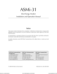
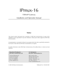
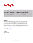
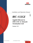
Figure 1-1 shows a Vmux-2100 application, where the gateway transmits
compressed voice over an IP network, including transparent transmission of CCS
and CAS signaling.
E1/T1 Trunks
Using CCS
E1/T1 Trunks
Using CCS
10/100BaseT
ISDN, SS7
PBX
10/100BaseT
Vmux-2100
PBX
Vmux-2100
IP Network
E1/T1 Trunks
Using CAS
E1/T1 Trunks
Using CAS
10/100BaseT
ISDN, SS7
PBX
10/100BaseT
Vmux-2100
PBX
Vmux-2100
Figure 1-1. Transmitting Compressed Voice and Signaling over IP Network
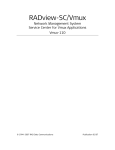
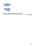
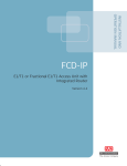
Figure 1-2 illustrates a Vmux-2100 implementing 16:1 TDMoIP compression to
transmit 480/384 voice channels over a single E1/T1 TDM link.
16 x E1/T1
Trunks
16 x E1/T1
Trunks
E1/T1
PBX
TDM
Network
Vmux-2100
E1/T1
PBX
Vmux-2100
Figure 1-2. Transmitting 480/384 Voice Channels over a Single E1/T1 Link
(16:1 Compression)
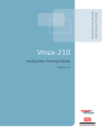
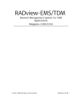
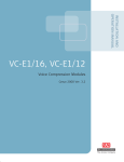
Figure 1-3 shows a central Vmux-2100 operating opposite three remote
Vmux-2100 units in a point-to-multipoint application.
Site A
10/100BaseT
PSTN
Vmux-2100
Central Site
E1/T1s
Site B
10/100BaseT
PSTN
E1/T1s
Vmux-2100
IP Network
10/100BaseT
E1/T1s
PSTN
Vmux-2100
Site C
E1/T1s
10/100BaseT
PSTN
Vmux-2100
Figure 1-3. Transmitting Compressed Voice in Point-to-Multipoint Application
1-2
Overview
Vmux-2100 Installation and Operation Manual
Chapter 1 Introduction
Features
E1 Main Link
Balanced redundant E1 main links ports use HDB3 coding and comply with
G.703, G.704, G.706, G.732 and G.823 standards. The E1 framers support
pass-through, G.732S and G.732N framing with or without CRC-4. Integral
LTU/DSU can be enabled for line protection and long haul options. Unbalanced
E1 connection is achieved via an external interface adapter.
T1 Main Link
Balanced redundant T1 main link ports use AMI coding, B8ZS zero suppression,
and comply with ANSI T1.403, AT&T TR-62411 and ITU-T G.703 standards. The
T1 framers support pass-through, SF, ESF. Integral DSU/CSU can be enabled for
line protection and long haul options.
Ethernet Main Link
Vmux-2100 has a half/full duplex, 10/100BaseT Ethernet port with autonegotiation
support. If autonegotiation is disabled, Vmux-2100 can be configured to any of the
following:
•
10BaseT – half or full duplex
•
100BaseT – half or full duplex.
The main link Ethernet port supports direct and indirect connection to the IP
networks.
Voice Modules
Vmux-2100 voice modules control E1/T1 frames, use G.723.1 (6.4 or 5.3 kbps),
G.729 A (8 kbps) and G.711 compression algorithms, and handle CAS/CCS
signaling transparently. Every group of two E1s or T1s is assigned a separate IP
address.
Voice Activity Detection mechanism allows optimizing bandwidth utilization, as
Vmux-2100 generates traffic only when voice activity is detected. Vmux-2100 uses
the G.723.1 A and G.729 B techniques for silence suppression and the G.168
standard for echo cancellation (up to 16 ms per channel). Vmux-2100 detects,
generates and relays DTMF/MFR2/MFC signals. In addition, Vmux-2100 supports
Group III fax relay (4.8, 9.6, 14.4 kbps) and transmits voice-band modem data.
Voice modules are hot-swappable.
TDMoIP Multiplexing
Vmux-2100 encapsulates the payload bytes in a UDP frame that is transferred over
IP and over Ethernet.
The number of TDM bytes in a multiplexed frame and packetizing interval are
user-configurable.
A destination IP address can be configured for each bundle (see Bundling, below).
Overview
1-3
Vmux-2100 Installation and Operation Manual
Chapter 1 Introduction
Bundling
Bundle is a logical internal port of Vmux-2100, containing up to 60 timeslots. Each
E1/T1 group handles up to five bundles. A bundle is routed to a defined remote IP
address (remote group address). Each timeslot can be included in any bundle
belonging to its E1/T1 group. At the remote site, it can be connected to any
timeslot within a destination bundle.
Bundle QoS support:
•
Labeling IP level priority (ToS).
•
VLAN tagging and priority labeling according to IEEE 802.1 p&q.
The user can configure the ToS (Type of Service) of the outgoing IP packets. This
allows an en-route layer 3 router or switch, which supports ToS, to give higher
priority to Vmux-2100 traffic for delay-sensitive and secure applications.
Vmux-2100 allows you to configure the whole ToS byte field, since different
vendors may use different bits to tag packets for traffic prioritization. This also
enables you to work according to various RFC definitions (for example RFC 2474,
RFC 791).
Timing
Available timing modes are:
•
Loopback – The E1 or T1 transmit clock is derived from the E1/T1 receive
clock.
•
Internal – Vmux-2100 features a separate internal oscillator for each voice
card. When a voice module is configured to operate in internal clock, transmit
(Tx) and receive (Rx) trunks use the clock supplied by its internal oscillator.
Diagnostics
Vmux-2100 supports local (internal) and remote (external) loopback activation on
E1/T1 links. The user can also perform tone injection towards the local PBX. In
addition, a ping utility is included to confirm IP connectivity to the remote units.
Statistics Collection
Vmux-2100 provides extensive statistics collection capabilities which include:
Ethernet (as per RFC 1643) and HDLC statistics, voice, signaling, bundles, CPU
and memory utilization.
Management
Vmux-2100 can be managed via a local terminal, Telnet or RADview, RAD’s
network management system. Vmux-2100 has a DB-9 female port for the direct
terminal connection. Alternatively, a supervisory terminal can be connected via a
modem link.
Software upload and download and configuration can be performed via the local
terminal, TFTP or via RADview. Remote units are managed via Telnet over an
inband management link running on an E1/T1 link.
1-4
Overview
Vmux-2100 Installation and Operation Manual
Chapter 1 Introduction
Vmux-2100 supports a four-level security and user-authentication system:
• Administrator – Allowed to configure all the parameters of Vmux-2100.
•
Operator – Allowed to perform all operations in the system except for user
administration (adding/deleting users, changing user definitions).
•
Technician – Allowed to test Vmux-2100 and monitor its operation (for
example, monitoring alarms).
•
Monitor – Allowed to monitor the Vmux-2100 operation.
When Vmux-2100 is managed over Telnet, up to five simultaneous management
sessions are allowed. Access to the Vmux-2100 software can be limited to the
ASCII terminal and RADview management by disabling the Telnet access.
Power
Vmux-2100 can be ordered with dual redundant hot-swappable power supplies,
supporting load sharing.
• AC: 100 to 240 VAC
•
DC: 30 to 70 VDC (48 VDC, nominal).
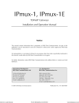
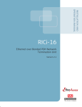
1.2 Physical Description
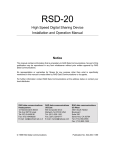
Vmux-2100 is a 1U high, easy-to-install standalone device. Figure 1-4 illustrates a
3-D view of the unit.
Figure 1-4. Vmux-2100, 3-D View
The front panel includes LEDs which indicate power supply, alarm and test
diagnostic status. The front panel indicators are described in Chapter 3.
The rear panel includes E1/T1 voice ports, DB-9 control port, Ethernet and E1/T1
main link connectors. These are described in Chapter 2.
Physical Description
1-5
Vmux-2100 Installation and Operation Manual
Chapter 1 Introduction
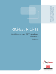
1.3 Functional Description
Figure 1-5 illustrates the block diagram of Vmux-2100.
Voice Module
Group 1
Main Module
Group 2
E1/T1
E1/T1
E1/T1
E1/T1
Voice Module
Group 1
Group 2
10/100BaseT Main Link
Control Port
Host
E1/T1
E1/T1
E1/T1
E1/T1
Ethernet
Switch
Voice Module
Group 1
Group 2
E1/T1 Main Link
E1/T1
E1/T1
E1/T1
E1/T1
Voice Module
Group 1
Group 2
E1/T1
E1/T1
E1/T1
E1/T1
Figure 1-5. Vmux-2100 Block Diagram
Voice Modules
Voice modules include two or four E1/T1 ports which receive E1/T1 trunks from
PBXs. Every two E1 and T1 ports are referred to as a group, which receives a
separate IP address.
Signaling
Signaling information is processed according to signaling mode: CAS for E1,
Robbed Bit MF for T1, or CCS for E1 and T1.
• CAS/Robbed Bit MF – The signaling data is processed by a separate DSP by
extracting the ABCD bits and reporting any change in their status to the host.
The reporting format is similar to E1, T1 ESF and T1 SF. In addition, the
signaling DSP employs a refresh mechanism to update the host with the most
recent status of the ABCD bits. The ABCD bits can be manipulated by using
translation rules, which are defined by means of signaling profiles.
A profile enables the user to select the translation of each individual signal bit.
The available selections are A, B, C, D (value copied from the corresponding
incoming bit), NOT A, NOT B, NOT C, NOT D (inverted value of
corresponding incoming bit), 0 (always 0), and 1 (always 1).
1-6
Functional Description
Vmux-2100 Installation and Operation Manual
•
Chapter 1 Introduction
In addition to the translation of individual bits, the signaling profiles can also
be used to define the signaling bit patterns that indicate the idle and OOS
states.
CCS – The signaling information is transferred transparently to the host, which
encapsulates the HDLC frame with the proper IP header and sends it to the
main link. The following protocols are supported: ISDN, QSIG and SS7. HDLC
data can be extracted from any set of timeslots and sent to a single destination.
When operating with SS7 signaling, it is possible to control amount of the
keep-alive bits transferred over the signaling links.
Compression
The DSPs handle the voice traffic by compressing it according to G.723.1 (6.4 or
5.3 kbps) and G.729 A (8 kbps), or digitizes it according to the G.711 requirements
(A-law and µ-law). Compression methods are user-selectable per bundle.
Voice Activity Detection
Voice Activity Detection (VAD) uses digital signal processing techniques to
distinguish between silence and speech on a voice connection. VAD reduces the
bandwidth requirements of a voice connection by generating traffic only during
periods of active voice conversation. With Comfort Noise Generation supported at
the remote site, VAD significantly reduces bandwidth consumption without
degrading voice quality. VAD achieves additional bandwidth savings when
combined with voice compression techniques.
TDMoIP Multiplexing
Compressed voice payload is multiplexed by using the TDMoIP technique. The
multiplexing is performed by the Vmux-2100 software. The DSPs send a
continuous stream of voice packets; which are put together into a TDMoIP frame
by adding AAL2 headers and a TDMoIP header. Figure 1-6 illustrates the TDMoIP
frame structure.
TDMoIP AAL2
Header Header
Voice
Packet
AAL2
Header
Voice
Packet
Figure 1-6. TDMoIP Frame Structure
The size of TDMoIP frame is determined by the following parameters:
•
Packetizing interval – Defining time interval allocated for the TDMoIP frame
aggregation (10 to 90 msec).
•
Maximum bytes per multiplexed frame – Specifying the maximum size of each
frame (100 to 1461 bytes).
Functional Description
1-7
Vmux-2100 Installation and Operation Manual
Chapter 1 Introduction
Ethernet Frame
At a later stage, the TDMoIP frame becomes a part of the standard Ethernet frame,
which also includes a UDP header, IP header and MAC. The Ethernet frames are
forwarded to the Ethernet switch, which sends them to one of the main links:
10/100BaseT or E1/T1. Figure 1-7 illustrates the structure of the Vmux-2100
Ethernet frame. Table 1-1 describes the fields of the Vmux-2100 Ethernet frame.
Ethernet
UDP
IP
TDMoIP AAL2 Voice AAL2 Voice AAL2 Voice Ethernet
Figure 1-7. Ethernet Frame Structure
Table 1-1. Ethernet Frame Fields
MAC
Layer
LLC
Layer
IP Layer
UDP
Layer
Data
Layer
MAC
Layer
1-8
Field Length (bytes)
Field
7
Preamble
1
SFD
6
Destination MAC Address
6
Source MAC Address
2
Type
1
Vers/HLEN
1
Service Type
2
Total Length
2
Identification
1
Flags/Fragment Offset (most)
1
Fragment Offset (least)
1
Time to Live
1
Protocol
2
Header Checksum
4
Source IP Address
4
Destination IP Address
2
UDP Source Port
2
UDP Destination Port
2
UDP Message Length
2
UDP Checksum
...
4
Functional Description
Payload
CRC
IEEE 802.1p&q VLAN Tagging
(additional 4 bytes if enabled)
Note: The UDP source port
field is used to transfer a
destination bundle number.
Vmux-2100 Installation and Operation Manual
Chapter 1 Introduction
VLAN Support
Vmux-2100 supports VLAN, according to IEEE 802.1p&q. When VLAN support is
enabled Vmux-2100 adds four bytes to the MAC layer of the Ethernet frame. The
content of these bytes, MAC layer priority and VLAN ID, can be set by the user. In
this mode, only VLAN format frames are sent and received by Vmux-2100. The
following figure describes the VLAN tag format.
00
8
802.1D Tag Protocol Type
(802.1QTagType)
6
VID
CFI = 0
user_priority
81
5
4
1
8
Priority
1
VLAN ID
Figure 1-8. VLAN Tag Format
UDP Support
Table 1-2. UDP Source Port as Destination Voice Port
Field Length (Bits)
Field Description
Value
2 bytes
UDP Source Port*
2 – 497d
2 bytes
UDP Destination Port
2142d
* – The MSB of this field can be either 1 or 0 for inband end-to-end proprietary signaling.
Note
The UDP Source Port field is used for destination voice bundle indication.
For example, if the destination is:
Bundle 1 – 02, Bundle 2 – 03, Bundle 3 – 04, Bundle 4 – 05, etc.
For more information about VLAN tagging, see IEEE Std 802.1 p&q.
Ethernet Main Link
10/100BaseT main link receives Ethernet frames from the voice modules via the
Ethernet switch and forwards them to the remote device over the IP network. The
10/100BaseT main link of Vmux-2100 supports full duplex transmission with
autonegotiation and half duplex with the backpressure option.
E1/T1 Main Link
When using E1/T1 main link, Vmux-2100 adds HDLC flags to the Ethernet frames
and transmits them over a TDM network. The E1/T1 main link interface of
Vmux-2100 is fully redundant. When both of links are configured as active,
Vmux-2100 starts sending data over the one that was connected first. If a loss of
synchronization is detected on an active link, Vmux-2100 automatically switches
to the backup link.
The E1/T1 links operate with loopback timing by deriving clock from the device
connected to its E1/T1 port or with internal clock provided by the Vmux-2100
internal oscillator.
Functional Description
1-9
Vmux-2100 Installation and Operation Manual
Chapter 1 Introduction
Bandwidth Utilization
By using TDMoIP multiplexing and the voice activity detection, Vmux-2100
supports a higher number of voice channels over TDM than it is possible by
utilizing conventional compression methods alone. TDMoIP multiplexing and
grouping the timeslots of compressed voice together into bundles with a common
IP address reduces the actual bandwidth used per channel to as low as 4 kbps
(16:1), when all channels are active. Better compression, up to 20:1, is achieved
when some of the voice channels are idle.
The actual bandwidth utilization is determined by the following factors:
• Header sizes:
•
Ethernet – 18 bytes
IP – 20 bytes
UDP – 8 bytes
TDMoIP – 4 bytes
VLAN (if exists) – 4 bytes.
Size of the voice packet:
•
G.723 – 24 bytes + AAL2 header (3 bytes) + voice payload (4 bytes)
G.729 – 10 bytes + AAL2 header (3 bytes) + voice payload (4 bytes).
Packet interval:
•
G.723.1 – 30 msec
G.729 – 10 msec.
Number of timeslots in a bundle
•
Silence percentage. Studies show that an average person speaks only 40% of
the time during a telephone conversation. 50% of the time is spent listening to
the other party, while the remaining 10% is spent quietly contemplating.
•
Connectivity packets – 64 bytes per minute.
Calculating Approximate Bandwidth Utilization
Let us calculate an approximate bandwidth for 30 timeslots in one bundle with
G.723.1 (6.4 kbps) compression, 60 % of silence:
[(50 × 1000/40) + (30 × 31 × 1000/30 × 0.4)] × 8
+ 0.00853 = 109.208 kbps
1000
where:
• 50 – size of Ethernet, IP, UDP, TDMoIP headers
1-10
•
1000/40 – packets per second (pps) transmission rate, calculated according to
the packetizing interval chosen (40 msec in this example)
•
30 – number of timeslots
•
31 – size of the compressed G.732 packet plus AAL2 header and voice payload
•
0.4 – 60% of silence
•
8 – conversion from bytes to bits
•
1000 in the denominator – conversion from bits to kilobits
•
0.00853 – connectivity packets rate (64 bytes per minute) converted to kbps.
Functional Description
Vmux-2100 Installation and Operation Manual
Chapter 1 Introduction
1.4 Technical Specifications
Ethernet
Main Link
Standards
IEEE 802.3, 802.3u, Ethernet 802.1p/q
Data Rate
10 or 100 Mbps, half duplex or full duplex,
autonegotiation support
Statistics
According to RFC 1643 or RFC 2665:
• Received frames – Correct Frames, Correct Octets,
Alignment Errors, FCS Errors
• Transmitted frames – Correct Frames, Correct
Octets, Single Collision, Multiple Collision, Deferred
Transmission, Late Collision, Carrier Sense Error
Range
Copper:
• Up to 100m (328 feet) over UTP Cat.5 cable
Fiber optic:
• 20 km (12 miles) over single-mode cable, 1310 nm
• 2 km (1.2 mile) over multimode cable, 1310 nm
Connector
Copper: RJ-45, 8-pin
Fiber optic: LC
E1 Main Link Number of Links
Two (one redundant)
Data Rate
2.048 Mbps
Standards
ITU-T Rec. G.703, G.704, G.706, G.732, G.823
Framing
G.732S and G.732N with or without CRC-4, in
compliance with ITU-T Rec. G.703, G.704, G.732
requirements
Line Code
HDB3
Receive Signal Level
0 to -43 dB with LTU
0 to -12 dB without LTU
Transmit Signal Level
Balanced: ±3V (±10%)
Unbalanced: ±2.37V (±10%)
Jitter Performance
Per ITU-T G.823
Timing
Internal or loopback
Line Impedance
120Ω, balanced
75Ω, unbalanced
Connector
Balanced: RJ-45, 8-pin
Unbalanced: via CBL-RJ45/2BNC interface adapter
Technical Specifications
1-11
Vmux-2100 Installation and Operation Manual
Chapter 1 Introduction
T1 Main Link
Number of Links
Two (one redundant)
Data Rate
1.544 Mbps
Standards
ANSI T1.403, AT&T TR-62411, ITU-T Rec. G.703
Line Code
AMI
Zero Suppression
B8ZS
Framing
SF, ESF, transparent
Timing
Internal or loopback
Statistics
Full statistical diagnostics capability according to
ANSI T1.403-1989
Local support of ESF diagnostics according to
AT&T PUB 54016
Receive Signal Level
0 to -36 dB with CSU
0 to -30 dB without CSU
Transmit Signal Level
0, -7.5, -15, or -22.5 dB with CSU
±2.7V (±10%) at 0–655 ft without CSU
E1 Voice
Ports
Jitter Performance
Per AT&T TR-62411
Line Impedance
100Ω, balanced
Ports per Module
Two or four
Data Rate
2.048 Mbps per port
Standards
ITU-T Rec. G.703, G.704, G.706, G.732, G.823
Framing
G.732S and G.732N with or without CRC-4, in
compliance with ITU-T Rec. G.703, G.704, G.732
requirements
Line Code
HDB3
Receive Signal Level
0 to -43 dB with LTU
0 to -12 dB without LTU
T1 Voice
Ports
1-12
Transmit Signal Level
±3V (±10%)
Jitter Performance
Per ITU-T G.823
Line Impedance
120Ω, balanced
Connector (per port)
RJ-45, 8-pin
Ports per Module
Two or four
Data Rate
1.544 Mbps per port
Standards
ANSI T1.403, ITU-T Rec. G.703
Technical Specifications
Vmux-2100 Installation and Operation Manual
Chapter 1 Introduction
Line Code
AMI
Zero Suppression
B8ZS
Framing
D4, ESF
Receive Signal Level
0 to -36 dB with CSU
0 to -30 dB without CSU
Transmit Signal Level
0, -7.5, -15, or -22.5 dB with CSU
±2.7V (±10%) at 0–655 ft without CSU
Voice
Processing
Control Port
Diagnostics
Jitter Performance
Per AT&T TR-62411, G.824
Line Impedance
100Ω, balanced
Connector (per port)
RJ-45, 8-pin
Compression
Algorithms
G.723.1 (5.3 or 6.4 kbps), G.729 A (8 kbps),
G.711 (a-law/µ-law)
Silence Suppression
G.723.1A, G.729B
Echo Cancellation
16 ms per channel as per G.168
Fax Relay
Group III: 4.8, 9.6, 14.4 kbps
Voice-Band Modem
Transparent transfer
MF Signaling
Support
DTMF, MFR2, MFC detection, generation and relay
Standard
V.24/RS-232 (DCE)
Data Rate
9.6, 19.2, 38.4 or 57.6 kbps
Connector
DB-9, female
Tests
Local and remote loopbacks, tone injection towards the
local PBX, ping utility
Statistics Collection
Main link module:
• Ethernet (as per RFC 1643)
• CPU utilization
Voice modules:
• Ethernet
• CPU utilization
• HDLC
• Bundles
• Voice
• Voice Rx and Tx signaling
• Memory utilization
Technical Specifications
1-13
Vmux-2100 Installation and Operation Manual
Chapter 1 Introduction
Indicators
Ethernet Main Link
ACT (yellow), blinks according to the Ethernet traffic
LINK (green), ON – Good link integrity
E1 Main Link and
Voice Port
LOC (red), ON – Local sync loss occurred
T1 Main Link and
Voice Port
RED (red), ON – Red alarm is received
General
PWR1 (green), ON – Power supply 1 is on
REM (red), ON – Remote sync loss occurred
YEL (red), ON – Yellow alarm is received
PWR2 (green), ON – Power supply 2 is on
ALM (red), ON – An alarm is present in the system
TST (yellow), ON – A test is active
POWER (green), ON – Power supply is on
POWER (red), ON – Power supply is off
Power Supply Number
Physical
AC Source
100 to 240 VAC, 50 or 60 Hz, 40W
DC Source
-36 to -72 VDC (-48 VDC, nominal)
Height
4.3 cm / 1.7 in (1U)
Width
43.5 cm / 17.1 in
Depth
24.0 cm / 9.5 in
Weight
7.0 kg / 15.5 lb
Environment Operating
Temperature
1-14
Two, redundant, hot-swappable
0 to 50°C / 32 to 122°F
Storage Temperature
-20 to 70°C / -4 to 158°F
Humidity
Up to 90%, non-condensing
Technical Specifications
Chapter 2
Installation and Setup
This chapter describes installation and setup procedures for the Vmux-2100
device.
After installing the unit:
•
Refer to Chapter 3 for the operating instructions.
•
Refer to Chapter 4 for the detailed system configuration procedures using an
ASCII terminal connected to the Vmux-2100 control port.
If a problem is encountered, refer to Chapter 5 for test and diagnostic instructions.
Internal settings, adjustment, maintenance, and repairs may be performed
only by a skilled technician who is aware of the hazards involved.
Always observe standard safety precautions during installation, operation, and
Warning maintenance of this product.
2.1 Site Requirements and Prerequisites
AC-powered Vmux-2100 units should be installed within 1.5m (5 ft) of an
easily-accessible grounded AC outlet capable of furnishing the voltage in
accordance with Vmux-2100 nominal supply voltage.
DC-powered Vmux-2100 unit requires a -48 VDC power source, which must be
adequately isolated from the main supply.
The trunk circuit which supplies power to the unit must be protected by a circuit
breaker of 16A maximum.
Allow at least 90 cm (36 in) of frontal clearance for operating and maintenance
accessibility. Allow at least 10 cm (4 in) clearance at the rear of the unit for signal
lines and interface cables.
The ambient operating temperature of Vmux-2100 is 0 to 50°C (32 to 122°F), at a
relative humidity of up to 90%, non-condensing.
Site Requirements and Prerequisites
2-1
Chapter 2 Installation and Setup
Vmux-2100 Installation and Operation Manual
2.2 Package Contents
The Vmux-2100 package includes the following items:
•
One Vmux-2100 unit
•
Vmux-2100 installation and operation manual
•
CBL-RJ45/2BNC, RJ-45 to BNC interface adapter (if ordered)
•
CBL-VMUX-MM-MODEM cross cable (if ordered)
•
AC power cord or DC power supply connector kit.
2.3 Installation and Setup
The Vmux-2100 unit is designed for desktop or bench installation and is delivered
as a fully assembled unit. No provisions are made for bolting the unit to a tabletop.
To install Vmux-2100:
1. Determine the required configuration of Vmux-2100, in accordance with your
application.
2. Set the E1 main link board internal jumpers to match E1 connection type:
balanced or unbalanced.
3. Connect the E1/T1 voice port.
4. Connect the 10/100BaseT or E1/T1 main link.
5. Connect an ASCII terminal or a PC running a terminal emulation software.
6. Connect power to the unit.
Setting the Main Link E1 Internal Jumpers
When using the E1 main link, set the E1 main link board internal jumpers to match
the E1 connection type: balanced or unbalanced. In addition, you can connect
pin 3 and pin 6 of the RJ-45 E1 main link connector to the frame ground.
To set the E1 main link board jumpers:
1. Disconnect all power and interface cables from Vmux-2100.
2. Release the two main link rear panel screws.
3. Slide the main link board interior out of the unit.
4. Set the E1 main link jumpers (see Figure 2-1 and Table 2-1).
2-2
Installation and Setup
Vmux-2100 Installation and Operation Manual
Chapter 2 Installation and Setup
JP7
FGND 3, 6
JP1
BAL
UNBAL
YES NO
BAL UNBAL
JP6
BAL
JP5
UNB
JP8
BAL UNBAL
BAL
JP11
UNBAL
BAL
JP9
BAL
JP13
UNBAL
JP10
JP12
UNB
FGND 3, 6
UNBAL
BAL
YES NO
JP14
JP16
Figure 2-1. E1 Main Link Jumper Locations
Table 2-1. E1 Main Link Jumper Settings
Jumper
Description
Values
Factory Setting
E1 interface type
jumpers, JP1, JP2,
JP5, JP6, JP8, JP9,
JP10, JP11, JP12,
JP13, JP14, JP15
Select the E1 interface type:
balanced or unbalanced.
BAL – E1 balanced interface
BAL
Shield ground
reference
jumpers,
JP16 (port A),
JP7 (port B)
Control connection between the
E1 cable shield (pin 3 and pin 6)
and the frame ground.
UNBAL – E1 unbalanced interface
All the jumpers must be set to the
same position (balanced or
unbalanced).
YES – Shields are connected to the
frame ground
(in compliance with ITU-T
I.431 requirements)
NO – Shields are not connected to NO
the frame ground
Connecting the Interfaces
Figure 2-2 shows the rear panel of an AC-powered Vmux-2100 unit.
2
LOC
VC-4E1
1
REM
1
2
3
REM
A
4
LOC
VC-4E1
LOC
E1
2
3
4
ETH/E1
CONTROL
3
LOC
VC-4E1
ACT LINK
REM
1
B
ETH
TST
4
ALM
VC-4E1
REM
1
2
3
4
LOC
POWER
POWER
Vmux
2100
REM
1
2
3
4
PS2 PS1
Figure 2-2. Vmux-2100 Rear Panel
Connecting the E1/T1 Voice Ports
Each E1/T1 voice port terminates in RJ-45 balanced connector. Appendix A
specifies the pinout of the E1 connector.
To connect the E1/T1 voice port:
•
AM
Connect the incoming E1/T1 link to the RJ-45 connector of the Vmux-2100
voice module, designated 1, 2, 3 or 4.
Installation and Setup
2-3
Chapter 2 Installation and Setup
Vmux-2100 Installation and Operation Manual
Connecting the Main Link
The Vmux-2100 Ethernet main link interface terminates in an 8-pin RJ-45
connector. Appendix A specifies the pinout of the Ethernet connector. The
Ethernet main link port supports connection via straight and cross cables.
To connect the Ethernet main link:
•
Connect the LAN to the RJ-45 connector designated ETH.
The E1/T1 main link interface terminates in an 8-pin RJ-45 balanced connector.
Appendix A specifies the pinout of the E1/T1 balanced connector.
To connect the balanced E1/T1 main link:
•
Connect the E1/T1 link to the RJ-45 connector designated E1 A or E1 B.
To connect the unbalanced E1 main link:
1. Insert the RJ-45 plug of the CBL-RJ45/2BNC adapter into the Vmux-2100
RJ-45 connector designated E1 A or E1 B.
2. Connect the coax cable to the BNC connectors of the CBL-RJ45/2BNC
adapter.
Connecting the ASCII Terminal
The Vmux-2100 control port terminates in a 9-pin D-type female interface
connector. Appendix A specifies the pinout of the control port connector.
To connect the ASCII terminal directly to the CONTROL port:
1. Connect the standard DB-9 flat cable to the 9-pin connector, designated
CONTROL.
2. Connect the other side of the cable to the ASCII terminal.
To connect the ASCII terminal via modem link:
1. Connect the VMUX connector of the CBL-VMUX-MM-MODEM cross cable to
the CONTROL port (see Appendix A for the cable wiring diagram).
2. Connect the MODEM connector of the cross cable to the local modem.
3. Connect the remote modem to the ASCII terminal.
2-4
Installation and Setup
Vmux-2100 Installation and Operation Manual
Chapter 2 Installation and Setup
Connecting the Power
Vmux-2100 includes two hot-swappable AC or DC power supplies, supporting
load sharing. To connect Vmux-2100 to the power source, refer to the appropriate
section below, depending on your version of the unit (AC or DC).
Warning
Before switching on this unit and connecting or disconnecting any other cable,
the protective earth terminals of this unit must be connected to the protective
ground conductor of the mains (AC or DC) power cord. If you are using an
extension cord (power cable) make sure it is grounded as well.
Any interruption of the protective (grounding) conductor (inside or outside the
instrument) or disconnecting of the protective earth terminal can make this
unit dangerous. Intentional interruption is prohibited.
The line fuse is located in an integral-type fuse holder located on the rear
panel. Make sure that only fuses of the required rating, as marked on the rear
panel, are used for replacement. Do not use repaired fuses or short-circuit the
fuse holder. Always disconnect the mains cable before removing or replacing
the fuse. Whenever it is likely that the fuse protection has been damaged,
make the unit inoperative and secure it against unintended operation.
Connecting AC Power
AC power is supplied to Vmux-2100 through a standard 3-prong plug with an
integral fuse holder (see Figure 2-2).
AC power should be supplied through the 5 ft (1.5m) standard power cable
terminated by a standard 3-prong plug. The cable is provided with the unit.
To connect AC power:
1. Connect the power cable(s) to the power connector(s) on the Vmux-2100 rear
panel.
2. Connect the power cable to the mains outlet.
The unit will be turned on automatically upon connection to the mains.
Connecting DC Power
To connect DC power:
•
AM
Refer to DC Power Supply Connection Supplement.
Installation and Setup
2-5
Chapter 2 Installation and Setup
2-6
Installation and Setup
Vmux-2100 Installation and Operation Manual
Chapter 3
Operation
This chapter provides the following information for Vmux-2100:
•
Vmux-2100 front-panel indicators
•
Operating procedures (turn-on, front-panel indications, performance
monitoring and turn-off).
Installation procedures given in Chapter 2 must be completed and checked before
attempting to operate Vmux-2100.
3.1 Front Panel Indicators
The front panel of Vmux-2100 includes a series of LED indicators that show the
current operating status of the unit (see Figure 3-1). Additional indicators are
located on the rear panel, as shown in Figure 3-2. Table 3-1 lists and describes the
Vmux-2100 indicators.
Vmux-2100
Figure 3-1. Vmux-2100, Front Panel
2
LOC
VC-4E1
1
VC-4E1
REM
1
2
3
LOC
4
LOC
REM
A
E1
2
3
4
ETH/E1
CONTROL
3
LOC
VC-4E1
ACT LINK
REM
1
B
ETH
TST
4
ALM
VC-4E1
REM
1
2
3
4
LOC
POWER
POWER
Vmux
2100
REM
1
2
3
4
PS2 PS1
Figure 3-2. Vmux-2100, Rear Panel
Table 3-1. Vmux-2100 LEDs
Name
Function
Location
TST (yellow)
ON – A test is active
Front panel and main
link module
ALM (red)
ON – Alarm is present
Front panel and main
link module
PWR1 (green)
ON – Power supply 1 is ON
Front panel
PWR2 (green)
ON – Power supply 2 is ON
Front panel
POWER
ON (green) – A power supply is ON
Power supply module
ON (red) – A power supply is OFF
Front Panel Indicators
3-1
Vmux-2100 Installation and Operation Manual
Chapter 3 Operation
Table 3-1. Vmux-2100 LEDs (Cont.)
Name
Function
Location
LINK (green)
ON – Good link integrity
Ethernet main link
connector
ACT (yellow)
Blinks according to the Ethernet traffic
Ethernet main link
connector
LOC (red)
ON – Local sync loss occurred
E1 main link and voice
port connector
REM (red)
ON – Remote sync loss occurred
E1 main link and voice
port connector
RED (red)
ON – Red alarm is received
T1 main link and voice
port connector
YEL (yellow)
ON – Yellow alarm is received
T1 main link and voice
port connector
3.2 Operating Vmux-2100
Turning On Vmux-2100
To turn on Vmux-2100:
•
Connect the power cord(s) to the mains.
The PWR1(2) indicator lights up and remains lit as long as Vmux-2100
receives power.
Normal Indications
Table 3-2 shows the correct status of the indicators a few seconds after power-up.
Table 3-2. Vmux-2100 Indicator Status
Indicator
Status
PWR1/PWR2
On
TEST
Off
ALM
On
L
Off
R
Off
If the above LED indications do not appear following initial power turn-on, refer to
Chapter 5 for the diagnostic test instructions.
Turning Off Vmux-2100
To turn off Vmux-2100:
•
3-2
Remove the power cord from the power source.
Operating Vmux-2100
Vmux-2100 Installation and Operation Manual
Chapter 3 Operation
3.3 Default Settings
Vmux-2100 is managed by an ASCII terminal or PC running a terminal emulation
program via menu-driven embedded software. Table 3-3 lists the default settings of
the Vmux-2100 configuration parameters.
Table 3-3. Vmux-2100 Default Settings
Parameter
Default Value
System
Set Host IP address
0.0.0.0
Set Subnet Mask
0.0.0.0
Set Default Gateway
0.0.0.0
Trap
public
Read
public
Write
private
Managers list
0.0.0.0
Telnet
Enable
Set Baud Rate
9600
Timeout
3
Dial-In Modem
Disable
Signaling Profile
SS7 Keep-Alive Suppression Rate
A
B
C
D
Idle
1
0
0
0
OOS
1
0
0
0
0% - No Suppression / Not SS7
Hub
Slot 1
NO CARD
Slot 2
NO CARD
Slot 3
NO CARD
Slot 4
NO CARD
Main Link (Lan Parameters)
Set Auto Negotiation
Enable
Set Max Capability
100BaseT full duplex
Main Link (E1 Parameters)
Connect
No
Frame
732S
Restoration Time
1 second
Clock Source
Lbt
Interface Type
Ltu
Idle Code
ff
Default Settings
3-3
Vmux-2100 Installation and Operation Manual
Chapter 3 Operation
Table 3-3. Vmux-2100 Default Settings (Cont.)
Parameter
Default Value
Main Link (T1 Parameters)
Connect
No
Clock Source
Lbt
Frame
Esf
Interface Type
Dsu
Line Code
B8ZS
Rx Sensitivity (CSU mode only)
LOW (-30 dB)
Tx Gain Level (CSU mode only)
0 dBm
Line Length (DSU mode only)
0-133 ft
Restoration Time
1 second
Idle Code
ff
Group
Ip Address
0.0.0.0
Bundle
3-4
Enter Bundle Number
1
Connect
No
Function
TDMoIP
Max Bytes In Multiplexed Frame
500
Destination IP
0.0.0.0
Destination Bundle
1
Packetizing Interval
30
Connectivity Packet Rate
60
Connectivity Timeout Cycles
3
TOS Parameters (Precedence)
Routine
TOS Parameters (Delay)
Normal
TOS Parameters (Throughput)
Normal
TOS Parameters (Reliability)
Normal Reliability
Coder/Rate
G.723.1/6.4
Fax/Modem
Enable
Fax/Modem (Rate)
4.8 kbps
MF Relay
Disable
Minimum Pulse Width
30 msec
Minimum Power Level
0 dBm
VLAN Parameters (Vlan exists)
No
VLAN Parameters (Vlan ID)
26
VLAN Parameters (Vlan Priority)
0
Default Settings
Vmux-2100 Installation and Operation Manual
Chapter 3 Operation
Table 3-3. Vmux-2100 Default Settings (Cont.)
Parameter
Default Value
External E1
Connect
No
Frame
732S
Restoration Time
1 second
Clock Source
Lbt
Interface Type
Ltu
Idle Code
ff
Signaling
CAS
Profile
1
External T1
Connect
No
Clock Source
Lbt
Frame
Esf
Interface Type
Dsu
Line Code
B8ZS
Rx Sensitivity (CSU mode only)
LOW (-30 dB)
Tx Gain Level (CSU mode only)
0 dBm
Line Length (DSU mode only)
0-133 ft
Restoration Time
1 second
Idle Code
ff
Signaling
CAS
Profile
1
External Timeslot
Update from Time Slot
1
To Time Slot
1
Type
N.C.
Bundle
1
Destination Port ID
1
Destination Time Slot
1
Default Settings
3-5
Chapter 3 Operation
3-6
Default Settings
Vmux-2100 Installation and Operation Manual
Chapter 4
Management from a
Terminal
The configuration of Vmux-2100 is performed via menu-driven embedded
software, using a standard ASCII terminal or a PC running a terminal emulation
application connected to the rear panel CONTROL port. Alternatively, you can
configure Vmux-2100 via Telnet connection, which also establishes an inband
management link to the remote unit.
4.1 Preparing for the Control Session
This section describes how to prepare Vmux-2100 and the supervisory terminal for
the control session.
Control Port Interface Characteristics
Vmux-2100 includes a V.24/RS-232 asynchronous DCE port, designated
CONTROL and terminated in a 9-pin D-type female connector. The control port
continuously monitors the incoming data stream and immediately responds to any
input string received through this port.
The terminal can be connected either directly to the Vmux-2100 control port, or
through a modem or any other type of full-duplex data link.
•
Direct connection to terminals. Since terminals usually have DTE interfaces,
the connection to the port is made by means of a straight cable.
•
Connection through a modem or data link. In this case, you need a cross cable
(RAD’s CBL-VMUX-MM-MODEM) to connect to the CONTROL connector
(see Appendix A for the cross cable wiring diagram).
Preparing the Terminal
Any standard ASCII terminal (a “dumb” terminal or a personal computer running
a terminal emulation application) equipped with a V.24/RS-232 communication
interface can be used to configure Vmux-2100. Appendix A details the pin
assignment and control signal directions of the Vmux-2100 control connector.
Data Terminal Ready (DTR)
When connected and turned on, the terminal sets the DTR line ON (active) to gain
control over Vmux-2100 and starts a configuration or monitoring session.
Preparing for the Control Session
4-1
Chapter 4 Management from a Terminal
Vmux-2100 Installation and Operation Manual
Initiating a Control Session
Vmux-2100 supports two default terminal rates:
•
115.2 kbps, for 20–30 seconds after the power-up, until the boot sequence is
completed. Supervisory terminal connection may be required at this stage for
software downloading purpose.
•
9.6 kbps, during normal operation.
To initiate a control session:
1. Connect the terminal cable to the CONTROL connector of Vmux-2100.
2. Turn the control terminal on.
3. Configure the terminal to the default communication parameters: 9.6 kbps,
one start bit, eight data bits, no parity, one stop bit, no flow control, VT100
emulation.
You are now ready to start a control session.
Levels of Security
Vmux-2100 supports a four-level security and user authentication system:
•
Administrator – Allowed to configure all the parameters of Vmux-2100.
•
Operator – Allowed to perform all operations in the system, except for user
administration (adding/deleting users, changing user definitions).
•
Technician – Allowed to test Vmux-2100 and monitor its operation (for
example, monitoring alarms).
•
Monitor – Allowed to monitor the Vmux-2100 operation.
The maximum number of the users supported by Vmux-2100 is 20. When
managing Vmux-2100 over Telnet, up to five simultaneous management are
permitted. Only one administrator is allowed to enter the management session at a
time.
Vmux-2100 displays the management menus in accordance with a user’s access
rights. For example, configuration screens dealing with the unit configurations are
not available for the users, who logged in as technicians or monitors.
Default Security Configuration
Vmux-2100 is supplied with one administrator account:
•
User name: admin
•
Password: 12345.
When the first management session is initiated, it is recommended to create a new
administrator account, and delete the default one.
Note
4-2
If the password is lost, consult your local RAD distributor.
Preparing for the Control Session
Vmux-2100 Installation and Operation Manual
Chapter 4 Management from a Terminal
4.2 Navigating the Management Menus
This section provides a general description of the software menu operation and
conventions for navigating the menus. Appendix C lists all menus of the
Vmux-2100 management software.
Selecting Parameters
To choose an option:
•
Type the number corresponding to the option, and press <Enter>.
The screen for the selected option is displayed.
To correct an erroneous entry:
•
Press <Backspace> to clear the error, then enter the correct characters.
or
Press <Esc> to exit the current menu, and then return to the menu to
re-enter the required value.
Saving and Aborting Selected Values
You must save the selected values by updating the Vmux-2100 database. If the
database is not updated, Vmux-2100 discards all the user settings when it is reset.
You can save selected values at any stage of the configuration procedure.
Alternatively, you can abort the new settings and return to the previous values.
To save the changes:
1. Type @ and press <Enter>.
Vmux-2100 displays the following confirmation message:
Are you sure you want to update data base ?
Press Y/N :
2. Type Y to save the changes.
Note
Each time you update the Vmux-2100 database, the management software analyzes
the changes. If a major error is detected, Vmux-2100 aborts the database update
and displays the following message:
Data base wasn't changed. Sanity Error
- Check alarm.
In this case, check the sanity error, as described in Chapter 7, and re-enter the
erroneous values.
To undo the changes:
1. Type # and pressing <Enter>.
Vmux-2100 displays the following confirmation message:
Are you sure you want to undo data base ?
Press Y/N :
2. Type Y to abort the changes and use the previous database settings.
Navigating the Management Menus
4-3
Vmux-2100 Installation and Operation Manual
Chapter 4 Management from a Terminal
4.3 Starting the Control Session
Once you have installed Vmux-2100, and completed the installation and
operation procedures described in Chapter 2 and Chapter 3, you can start the
control session.
You have to enter a user name and password in order to start the Vmux-2100
management software (see Figure 4-1).
USERNAME:
PASSWORD:
ESC - clear; & - exit
Figure 4-1. Password Request Screen
To enter the user name and password:
1. Type in your user name, and press <Enter>.
2. Type in your password (up to eight characters), and press <Enter>.
The Main menu is displayed (see Figure 4-2).
Main Menu
1. Inventory
2. Configuration
3. Monitoring
4. Diagnostics
@ - Db Update; # - Db Undo
ESC-prev.menu; !-main menu; &-exit
Figure 4-2. Main Menu
4-4
Starting the Control Session
Vmux-2100 Installation and Operation Manual
Chapter 4 Management from a Terminal
4.4 Displaying the Vmux-2100 Inventory
Vmux-2100 inventory displays information on the types of the voice modules
detected in the unit, together with their hardware and software versions.
To display the Vmux-2100 inventory:
•
From the Main menu, choose Inventory.
The Vmux-2100 inventory screen appears (see Figure 4-3).
Inventory
Main
Slot 1
Slot 1
Slot 2
Slot 2
Slot 3
Slot 3
Slot 4
Slot 4
Name
Module
Main link IP
Group 1
Not exist
Group 2
Not exist
Group 1
2E1 Voice
Group 2
Not exist
Group 1
Not exist
Group 2
Not exist
Group 1
Not exist
Group 2
Not exist
HW Revision
01.00
SW Revision
01.00
00.00
01.00
@ - Db Update; # - Db Undo
ESC-prev.menu; !-main menu; &-exit
Figure 4-3. Vmux-2100 Inventory
4.5 Configuring the Vmux-2100 System
The Vmux-2100 management software allows you to perform the following:
•
Configuring parameters of the Ethernet management connection
•
Managing the user database (adding/deleting/changing user details)
•
Configuring control port for ASCII terminal connection
•
Defining the signaling bits table (for CAS signaling)
•
Configuring SS7 keep-alive suppression rate (for CCS signaling)
•
Controlling the software versions (see Appendix B)
•
Changing the real-time system clock settings
•
Resetting Vmux-2100.
To display the System Configuration menu:
1. From the Main menu, choose Configuration.
The Configuration menu appears (see Figure 4-4).
Configuring the Vmux-2100 System
4-5
Vmux-2100 Installation and Operation Manual
Chapter 4 Management from a Terminal
Configuration
1. System
2. Hub
3. Card
@ - Db Update; # - Db Undo
ESC-prev.menu; !-main menu; &-exit
Figure 4-4. Configuration Menu
2. From the Configuration menu, choose System.
The System menu appears (see Figure 4-5).
System
1. Management
2. Control Port
3. Date & Time Update
4. Factory Default
5. Show Partition information
6. Set the Active Application
7. Reset Card
8. Open Internal Alarms
@ - Db Update; # - Db Undo
ESC-prev.menu; !-main menu; &-exit
Figure 4-5. System Menu
Configuring Ethernet Management Connection
Vmux-2100 can be managed by a network management station, which is located
on the LAN connected to the unit’s 10/100BaseT port. In order to establish a
proper connection, it is necessary to configure the following:
• Host IP address, subnets mask, default gateway, its trap, read and write
communities.
•
Manager IP addresses.
Configuring the Host IP
The management host parameters are configured via the Host IP menu.
To configure the IP host parameters:
1. From the System menu, choose Management.
The Management menu appears (see Figure 4-6).
4-6
Configuring the Vmux-2100 System
Vmux-2100 Installation and Operation Manual
Chapter 4 Management from a Terminal
Management
1. Host IP
2. Manager List
3. Host Mux Name
...
4. User Administration
5. Signaling Configuration
6. Telnet
(Enable)
@ - Db Update; # - Db Undo
ESC-prev.menu; !-main menu; &-exit
Figure 4-6. Management Menu
2. From the Management, choose Host IP.
The Host IP menu appears (see Figure 4-7).
Host IP
1. Set Host IP address
... (170.185.190.15)
2. Set Subnet Mask
... (255.255.255.0)
3. Set Default Gateway
... (170.185.190.1)
4. Trap... (public)
5. Read... (public)
6. Write...(private)
@ - Db Update; # - Db Undo
ESC-prev.menu; !-main menu; &-exit
Figure 4-7. Host IP Menu
3. From the Host IP menu, choose the following:
Set Host IP address to define the host IP
Set Subnet Mask to define the subnet mask
Set Default Gateway to set the default gateway IP
Trap... to enter the name of a community to which the Vmux-2100 will
send traps
Read… to enter the name of a community with read-only authorization
Write… to enter the name of a community with write authorization.
4. Enter the desired value, and press <Enter>.
Configuring the Vmux-2100 System
4-7
Vmux-2100 Installation and Operation Manual
Chapter 4 Management from a Terminal
Defining the Manager List
You can define the network management stations to which the SNMP agent of
Vmux-2100 will send traps. Up to ten managers can be defined.
To define the manager list:
1. From the Management menu, choose Manager List.
The Manager List menu appears (see Figure 4-8).
Manager List
|
v
Managers ID
1
2
3
4
5
1. Change cell
>
IP Address
170.185.190.5
0.0.0.0
0.0.0.0
0.0.0.0
0.0.0.0
(170.185.190.5)
@ - Db Update; # - Db Undo
ESC-prev.menu; !-main menu; &-exit ?-help
Figure 4-8. Manager List Menu
2. Select a manager IP address by pressing <Shift> U to scroll up or <Shift> D
to scroll down.
3. Choose Change cell (type 1, and press <Enter>) to enter/edit the selected
manager IP address.
4. Enter the desired IP address, and press <Enter>.
Managing the User Database
An administrator manages the database of the users who are allowed to operate or
monitor the Vmux-2100 system. This allows the administrator to do the following:
•
Add a new user
•
Delete an existing user
•
Change user’s details, including the name, password or access level
•
Display the list of the users, including date and time
Adding a New User to the Database
To add a new user:
1. From the Management menu (see Figure 4-6), choose User Administration.
The User Administration menu appears (see Figure 4-9).
4-8
Configuring the Vmux-2100 System
Vmux-2100 Installation and Operation Manual
Chapter 4 Management from a Terminal
User Administration
1. Add New User
2. Delete User
3. Change User Details
4. Show All Users
>
@ - Db Update; # - Db Undo
ESC-prev.menu; !-main menu; &-exit
Figure 4-9. User Administration Menu
2. From the User Administration menu, choose Add New User.
The Add New User menu appears (see Figure 4-10).
Add New User
1. Enter UserName
... ()
2. Enter Access Level
>
3. Enter Password
...
4. Enter Password
>
...
(x)
@ - Db Update; # - Db Undo
ESC-prev.menu; !-main menu; &-exit
Figure 4-10. Add New User Menu
3. From the Add New User menu, choose Enter UserName.
4. Enter a new user name, and press <Enter>.
The new user name is displayed.
Note
User names are case-sensitive.
5. Choose Enter Access Level to define the new user access level.
6. Select the desired level (Monitor, Technician, Operator or Administrator).
The access level of a new user is displayed.
7. Choose Enter Password.
8. Enter the new user password (four to eight characters), and press <Enter>.
Vmux-2100 responds to the password entry with asterisks.
9. Choose Confirm Password and save.
10. Enter the new user password, and press <Enter> to save it.
Configuring the Vmux-2100 System
4-9
Vmux-2100 Installation and Operation Manual
Chapter 4 Management from a Terminal
Deleting an Existing User from the Database
To delete an existing user:
1. From the User Administration menu, choose Delete User.
The Delete User menu appears (see Figure 4-11).
Delete User
1. Enter UserName (to delete)
... ()
2. Confirm and delete
...
@ - Db Update; # - Db Undo
ESC-prev.menu; !-main menu; &-exit
Figure 4-11. Delete User Menu
2. From the Delete User menu, choose Enter UserName (to delete).
3. Enter the name of the user that you intend to delete, and press <Enter>.
4. From the Delete User menu, choose Confirm and delete.
5. Enter administrator password to confirm the deletion.
Changing the User Details
Administrator is allowed to change user’s password and access level.
To change user details:
1. From the User Administration menu, choose Change User.
The Change User Details menu appears (see Figure 4-12).
Change User Details
1. Enter UserName (to change)
... ()
2. Change password
...
3. Confirm and save password
...
4. Change access level
>
5. Confirm and save access level
(x)
...
@ - Db Update; # - Db Undo
ESC-prev.menu; !-main menu; &-exit
Figure 4-12. Change User Details Menu
2. From the Change User Details menu, choose Enter UserName (to change)
and then enter the name of the user, whose details you want to change.
3. To change the user password, choose Change password and then enter a new
password.
4-10
Configuring the Vmux-2100 System
Vmux-2100 Installation and Operation Manual
Chapter 4 Management from a Terminal
4. Choose Confirm and save password and then re-enter the new password to
confirm the change.
5. To change the user access level, choose Change access level and then enter a
new value (Monitor, Technician, Operator or Administrator) from the Change
Access Level menu.
6. Choose Confirm and save access level and then enter the administrator
password to confirm the change.
Displaying the User List
To display a list of registered users:
•
From the User Administration menu, choose Show all users.
The Show All Users screen appears (see Figure 4-13).
Show All Users
UserName
Access Level
DBchange Date
DBchange Time
1
admin
Administrator
6/3/2001
18:16:5
2
qwerty
Monitor
@ - Db Update; # - Db Undo
ESC-prev.menu; !-main menu; &-exit
Figure 4-13. Show All Users Screen
Controlling Telnet Access
You can disable Telnet access to Vmux-2100.
By disabling Telnet, you prevent unauthorized access to the system when security
of the Vmux-2100 IP address has been compromised. When Telnet access is
disabled, Vmux-2100 can be managed via an ASCII terminal or RADview.
To disable the Telnet access:
1. From the Management menu (Figure 4-6), choose Telnet.
The Telnet value toggles between Enable and Disable.
2. Set to ‘Disable’.
Configuring the Vmux-2100 System
4-11
Vmux-2100 Installation and Operation Manual
Chapter 4 Management from a Terminal
Configuring the Control Port
Vmux-2100 allows you to configure the baud rate, timeout period, and
connection of a dial-in modem to the rear panel CONTROL port.
Configuring the Data Rate
The Vmux-2100 control data port supports baud rates in the range of 9.6 to
115.2 kbps.
To configure the baud rate:
3. From the System menu (see Figure 4-5), choose Control Port.
The Control Port menu appears (see Figure 4-14).
Control Port
1. Set Baud Rate (bps) >
(9600)
2. Timeout (minutes)
[3 - 10]... (10)
3. Dial-In Modem
>
(Disable)
Please select item <1 to 3>
@ - Db Update; # - Db Undo
ESC-prev.menu; !-main menu; &-exit
Figure 4-14. Control Port Menu
4. Choose Set Baud Rate from the Control Port menu.
5. Select a new baud rate from the Set Baud Rate menu.
Configuring the Timeout
The timeout specifies a time interval after which Vmux-2100 automatically
disconnects from the supervisory terminal if no input from the user is detected.
The timeout can be set for between 3 to 10 minutes.
To configure the timeout:
1. From the Control Port menu, choose Timeout.
2. Enter the desired number of minutes and press <Enter>.
Enabling/Disabling Dial-in Modem Access
A dial-in modem can be connected to the CONTROL port for remote
management.
To enable or disable dial-in modem connection via the CONTROL port:
1. From the System menu (see Figure 4-5), choose Control Port.
The Control Port menu appears (see Figure 4-14).
2. From the Control Port menu, choose Dial-In Modem.
The Dial-In Modem menu appears.
4-12
Configuring the Vmux-2100 System
Vmux-2100 Installation and Operation Manual
Chapter 4 Management from a Terminal
3. From the Dial-In Modem menu, choose:
Disable to disable connection of a dial-in modem to the control port
Enable to enable connection of a dial-in modem to the control port.
Note
If an ASCII terminal or PC is connected directly to the control port while the dial-in
modem access option is enabled, signals from the terminal or PC may be confused
with modem control signals by the Vmux-2100 modem auto detect capability and
inadvertently cause the Vmux-2100 to disable the terminal or PC connection. To
avoid this situation, verify that the Control port dial-in modem access is set to
Disable (this is the default setting) before attempting to make a direct terminal or
PC connection to the Control Port (this can be accomplished safely via Telnet). If
dial-in modem access is not required, it is recommended to leave this option
disabled.
Configuring Signaling Information
Vmux-2100 allows you to configure the signaling parameters according to the
selected signaling mode: CAS for E1, Robbed Bit MF for T1 or CCS for E1/T1.
Signaling mode is selected via the E1 Parameters menu of the voice card (see the
Configuring External E1/T1 Ports section below).
•
CAS/Robbed Bit MF – You must configure a signaling profile and signaling
table associated with it (ABCD bits, idle code and OOS signals).
•
CCS – When working with CCS-SS7, you can configure the fill-in packets flow
by selecting the SS7 keep-alive suppression rate.
Configuring Signaling Profiles
If you are using CAS signaling, you must configure the signaling system of
Vmux-2100 to make it compatible with the signaling method used by the PBXs
connected to the voice E1/T1 ports. The management software allows you to
manipulate the ABCD signaling bits and methods of representation of the idle
code and out-of-service signals generated by the PBXs (see Table 4-1). Signaling
conversion is used for connection of PBXs, which use different signaling formats.
You can store up to five signaling profiles; Vmux-2100 uses only one of them at a
time. The signaling profile selection is performed via the E1 Parameters menu of
the voice card (see the Configuring External E1/T1 Ports section below).
Note
The signaling profile configuration is available only for the units operating with CAS
signaling.
To configure the signaling profile:
1. From the Management menu (see Figure 4-6), choose Signaling Configuration
The Signaling Configuration menu appears (see Figure 4-15).
Configuring the Vmux-2100 System
4-13
Vmux-2100 Installation and Operation Manual
Chapter 4 Management from a Terminal
Signaling Configuration
1. Signaling Profile Configuration
2. SS7 Keep-Alive Suppression Rate
(0% - No Suppression / Not SS7)
@ - Db Update; # - Db Undo
ESC-prev.menu; !-main menu; &-exit
Figure 4-15. Signaling Configuration Menu
2. From the Signaling Configuration menu, choose Signaling Profile
Configuration.
The Signaling Profile Configuration menu appears (see Figure 4-16).
Signaling Profile Configuration
1. Enter Profile Number To Configure [1 - 5... (1)
2. Signaling Table Configuration
[]>
@ - Db Update; # - Db Undo
ESC-prev.menu; !-main menu; &-exit
Figure 4-16. Signaling Profile Configuration Menu
3. From the Signaling Profile Configuration menu, choose Enter Profile Number
To Configure.
4. Enter the number of the signaling profile that you want to configure by typing a
number from 1 to 5, and pressing <Enter>.
5. From the Signaling Profile Configuration menu, choose Signaling Table
Configuration.
The Signaling Table Configuration menu appears (see Figure 4-17).
Signaling Table Configuration
ABCD BITS
IDLE SIGNAL
OOS SIGNAL
1.
2.
3.
4.
5.
6.
7.
0
1
A
NOT A
B
NOT B
C
A Bit
A
1
1
B Bit
B
0
0
C Bit
C
1
1
D Bit
D
1
1
8. NOT C
9. D
10. NOT D
@ - Db Update; # - Db Undo
ESC-prev.menu; !-main menu; &-exit ?-help
Figure 4-17. Signaling Table Configuration Menu
4-14
Configuring the Vmux-2100 System
Vmux-2100 Installation and Operation Manual
Chapter 4 Management from a Terminal
6. In the signaling table, select a signaling bit that you want to configure by
pressing <Tab>.
7. Configure the signaling bit by typing a number corresponding to the desired
value (see Table 4-1), and pressing <Enter>.
Table 4-1. Signaling Bits Configuration
Parameter
Description
Value
A, B, C, D Bit
Selects which incoming bit
(from the remote side) to
transmit on the A bit toward
the Vmux-2100’s local PBX.
0 – Transmits zero
1 – Transmits one
A – Transmits the incoming A bit
B – Transmits the incoming B bit
C – Transmits the incoming C bit
D – Transmits the incoming D bit
NOT A – Inverts the incoming A bit and transmits it
NOT B – Inverts the incoming B bit and transmits it
NOT C – Inverts the incoming C bit and transmits it
NOT D – Inverts the incoming D bit and transmits it
IDLE SIGNAL
OOS SIGNAL
Selects the code transmitted
on A, B, C, and D bit when the
channel is idle
0 – Transmits zero
Selects the code transmitted
on A, B, C, and D bit when the
channel is out of service
0 – Transmits zero
1 – Transmits one
1 – Transmits one
Configuring Keep-Alive Suppression Rate
When Vmux-2100 with CCS signaling is connected to the PBXs operating with the
SS7 signaling, the PBXs use one timeslot to transmit signaling information. The
signaling information is passed over the signaling link in the form of the following
signal units:
•
Message signal units (MSUs) provide all signaling associated with call setup
and tear down, database query and response, and SS7 network management.
•
Link status signal units (LSSUs) provide information on the link status
between the network nodes (initiation of link alignment, quality of the
signaling traffic etc).
•
Fill-in signal units (FISUs) carry no information payload. They occupy the link,
when there are no MSUs or LSSUs to send. FISUs are also referred to as
“keep-alive” messages.
Often, in the absence of signaling traffic, the signaling links become flooded with
the FISUs, causing communication disruptions. In order to prevent this, you can
enforce Vmux-2100 to drop certain amount of FISUs (up to 90%). You can also
disable the FISU dropping by configuring the keep-alive suppression rate to 0%. It
is necessary, when working with non-SS7 CCS signaling (for example ISDN), or if
the FISUs are used to acknowledge the receipt of the signaling messages. In the
latter case, system performance may become unsatisfactory.
Configuring the Vmux-2100 System
4-15
Chapter 4 Management from a Terminal
Vmux-2100 Installation and Operation Manual
To configure the keep-alive suppression rate:
1. From the Signaling Configuration menu (see Figure 4-15), choose
SS7 Keep-Alive Suppression Rate.
The SS7 Keep-Alive Suppression Rate menu appears (see Figure 4-18).
SS7 Keep-Alive Suppression Rate (0%)
1. 0% - No Suppression / Not SS7
2. 10%
3. 20%
4. 30%
5. 40%
6. 50%
7. 60%
8. 70%
9. 80%
10. 90%
>
Please select item <1 to 10>
@ - Db Update; # - Db Undo
ESC-prev.menu; !-main menu; &-exit
Figure 4-18. SS7 Keep-Alive Suppression Rate Menu
2. From the SS7 Keep-Alive Suppression Rate menu, type a number
corresponding to the desired value, and press <Enter>.
Assigning a Name to Vmux-2100
The Vmux-2100 management software allows you to assign a name to the unit to
distinguish it from the other devices installed in your system.
To assign a name:
3. From the Management menu (see Figure 4-6), choose Host Mux Name
4. Enter a name for the Vmux-2100, and press <Enter>.
Assigned name appears at the top of each terminal screen.
Setting Date and Time
You can set the time for the Vmux-2100 internal real-time clock.
To set date and time:
1. From the System menu (see Figure 4-5), choose Date & Time Update.
The Date & Time Update menu appears (see Figure 4-19).
4-16
Configuring the Vmux-2100 System
Vmux-2100 Installation and Operation Manual
Chapter 4 Management from a Terminal
Date & Time Update
1. Set Time (hh:mm)... (13:23)
2. Set Date (dd/mm/yyyy)... (4/2/2002)
@ - Db Update; # - Db Undo
ESC-prev.menu; !-main menu; &-exit
Figure 4-19. Date & Time Update Menu
2. From the Date & Time Update menu, choose Set Time.
3. Enter a new time value in the hh:mm format, and press <Enter>.
4. From the Date & Time Update menu, choose Set Date.
5. Enter a new date value in the dd/mm/yyyy format, and press <Enter>.
4.6 Entering Main Link and Voice Modules into the
Database
Before starting the configuration process of the 10/100BaseT and E1/T1 ports of
Vmux-2100, it is necessary to identify the modules installed in your system and
enter their types into the unit database. You can perform identification prior to the
physical installation of the modules. This allows you to reduce the system
downtime by preparing Vmux-2100 for a new configuration or upgrade.
Note
You can check the number and types of the main link and voice modules currently
installed in Vmux-2100 by displaying the unit’s inventory (Main Menu > Inventory).
To identify the modules:
1. From the Configuration menu, choose Hub.
The Hub menu appears (see Figure 4-20).
Hub
1. Main Board >
(M-IPE1)
2. Slot 1
>
(NO CARD)
3. Slot 2
>
(NO CARD)
4. Slot 3
>
(NO CARD)
5. Slot 4
>
(NO CARD)
@ - Db Update; # - Db Undo
ESC-prev.menu; !-main menu; &-exit
Figure 4-20. Hub Menu
2. From the Hub menu, choose Main Board to select the main link module.
The Main Board menu appears.
Entering Main Link and Voice Modules into the Database
4-17
Chapter 4 Management from a Terminal
Vmux-2100 Installation and Operation Manual
3. From the Main Board menu, select one of the following module types:
M-IP – 10/100BaseT port only
M-IPE1 – 10/100BaseT port and E1 port
M-IPT1 – 10/100BaseT port and T1 port.
4. From the Hub menu, choose Slot 1 to select the slot 1 module.
The Slot 1 menu appears.
5. From the Slot 1 menu, select one of the following module types:
NO CARD – No module installed in slot 1
V-2E1 – Two E1 ports
V-4E1 – Four E1 ports
V-2T1 – Two T1 ports
V-4T1 – Four T1 ports.
6. Repeat step 4 and step 5 to select the module types for all utilized Vmux-2100
slots.
4.7 Configuring Main Link and Voice E1/T1 Ports
Once the main link and voice E1/T1 modules are installed in Vmux-2100 and
identified by the system, you can start configuring the E1/T1 and Ethernet
connections of the unit.
It is recommended to configure the main link and voice (external) E1/T1 ports in
the following order:
1. Configure the main link:
Set the Ethernet parameters of the main link 10/100BaseT port, if necessary
(autonegotiation or LAN mode).
Configure the E1/T1 parameters of the main link, if necessary (framing
mode, restoration time, clock source, interface type, idle code).
Assign the E1/T1 main link timeslots to carry user data.
2. Configure external E1/T1 at a group (two E1/T1 ports of the same module)
level:
Assign IP address to a group.
Add bundles to a group (up to five bundles per group)
Configure each bundle (frame size, destination IP, destination bundle,
packetizing interval, TOS parameters, compression method, fax relay,
VLAN parameters).
3. Configure external E1/T1 at a single E1/T1 level:
Configure each E1/T1 port at the physical level (framing mode, restoration
time, clock source, interface type, idle code, signaling type, signaling
profile).
4-18
Configuring Main Link and Voice E1/T1 Ports
Vmux-2100 Installation and Operation Manual
Chapter 4 Management from a Terminal
Configure the timeslots of each E1/T1 port (voice or data, mapping to
specific bundles, routing to remote ports and timeslots).
Configuring the Main Link
The main link module of Vmux-2100 may include 10/100BaseT port and E1/T1
port.
Configuring the Ethernet Port
The Ethernet port of the Vmux-2100 main link module supports autonegotiation. If
the autonegotiation is disabled, the Ethernet port can be configured to operate in
10BaseT (half duplex or full duplex) or 100BaseT (half duplex or full duplex)
mode.
To configure the Ethernet port:
1. From the Configuration menu (see Figure 4-4), choose Card.
The Card menu appears (see Figure 4-21).
Card
1. Main board
2. Slot 1
3. Slot 2
@ - Db Update; # - Db Undo
ESC-prev.menu; !-main menu; &-exit
Figure 4-21. Card Menu
2. From the Card menu, choose Main board.
The Main Board menu appears (see Figure 4-22).
Main Board
1. Lan Parameters
2. E1 Parameters
@ - Db Update; # - Db Undo
ESC-prev.menu; !-main menu; &-exit
Figure 4-22. Main Board Menu
3. From the Main Board menu, choose Lan Parameters.
The Lan Parameters menu appears (see Figure 4-23).
Configuring Main Link and Voice E1/T1 Ports
4-19
Vmux-2100 Installation and Operation Manual
Chapter 4 Management from a Terminal
Lan Parameters
1. Set Auto Negotiation
2. Set Capability
>
(Disable)
(100baseT Full Duplex)
@ - Db Update; # - Db Undo
ESC-prev.menu; !-main menu; &-exit
Figure 4-23. Lan Parameters Menu
4. From the Lan Parameters menu, choose Set Auto Negotiation to enable or
disable the autonegotiation.
5. If the autonegotiation is disabled, choose Set Capability from the Lan
Parameters menu.
The Set Capability menu appears.
6. Select the desired LAN operation mode by choosing one of the following:
10BaseT half duplex
10BaseT full duplex
100BaseT half duplex
100BaseT full duplex.
Configuring the E1 Main Link Port
The M-IPE1 main link modules include two fully redundant E1 ports. When both
of them are configured as active, Vmux-2100 starts sending data over the one that
has been connected first. If a loss of synchronization is detected on an active link,
Vmux-2100 automatically switches to the backup.
To configure the main link E1 port:
1. From the Main Board menu (see Figure 4-22), choose E1 Parameters.
The E1 Parameters menu appears (see Figure 4-24).
E1 Parameters
1. Main Link 1
2. Main Link 2
3. Time Slot Table
@ - Db Update; # - Db Undo
ESC-prev.menu; !-main menu; &-exit
Figure 4-24. E1 Parameters Menu
2. From the E1 Parameters menu, choose Main Link 1 to configure E1 port 1 or
choose Main Link 2 to configure E1 port 2.
The Main Link 1/2 menu appears (see Figure 4-25).
4-20
Configuring Main Link and Voice E1/T1 Ports
Vmux-2100 Installation and Operation Manual
Chapter 4 Management from a Terminal
Main Link 1 or Main Link 2
1. Connect > (Yes)
2. Frame
>
(G.732S)
3. Restoration Time>
4. Clock Source>
5. Interface Type>
6. Idle Code
(CCITT)
(Lbt
(Local))
(Ltu)
[0 - ff]... (ff)
@ - Db Update; # - Db Undo
ESC-prev.menu; !-main menu; &-exit
Figure 4-25. Main Link 1/2 Menu for E1 Port Module
3. From the Main Link 1/2 menu, configure the following E1 parameters:
Connect:
Yes (E1 link is enabled)
No (E1 link is disabled).
Frame (E1 framing mode):
G.732N (256N multiframe, 2 frames per multiframe, CRC-4 function
disabled)
G.732N-CRC4 (256N multiframe, 2 frames per multiframe, CRC-4
function enabled)
G.732S (256S multiframe, 16 frames per multiframe, CRC-4 function
disabled)
G.732S-CRC4 (256S multiframe, 16 frames per multiframe, CRC-4
function enabled).
Restoration Time (time required for the E1 port to return to normal
operation after sync loss):
1 Second (after 1 second, fast)
10 Second (as per requirements of AT&T TR-62411)
CCITT (as per requirements of ITU-T Rec.G.732).
Clock Source:
Lbt (derived from the received E1 signal)
Internal (received from the Vmux-2100 internal oscillator).
Interface Type (maximum attenuation of the Rx signal that can be
compensated for by the port Rx path, to obtain BER performance required
by the standards):
Ltu (maximum attenuation of 43 dB, relative to the nominal transmit
level of 0 dB, operates at longer ranges)
Dsu (maximum attenuation of 12 dB, relative to the nominal transmit
level of 0 dB).
Configuring Main Link and Voice E1/T1 Ports
4-21
Vmux-2100 Installation and Operation Manual
Chapter 4 Management from a Terminal
Idle Code (code transmitted to fill unused timeslots in the E1 frames):
00 to ff.
4. From the E1 Parameters menu, choose Time Slot Table to assign the E1 main
link to carry the user data (and idle code).
The Time Slot Table menu appears.
Timeslots that are connected (assigned to carry data) are marked Yes; timeslots
that are disconnected (not assigned) are marked No.
Time Slot Table
Ts#
1
Yes
2
Yes
3
Yes
4
No
5
No
6
No
7
No
Ts#
13
No
14
No
15
No
16
No
17
Yes
18
No
19
No
Ts#
25
No
26
No
27
No
28
No
29
No
30
No
31
No
8
No
20
No
9
No
21
No
10
No
11
No
12
No
22
No
23
No
24
No
1. No
2. Yes
>
@ - Db Update; # - Db Undo
ESC-prev.menu; !-main menu; &-exit
Figure 4-26. Time Slot Table (for E1 Link)
5. From the Time Slot Table, toggle between timeslots by pressing <Tab>, and
assign the timeslot(s) that are to carry data by entering Yes. To disconnect a
timeslot, enter No.
Note
Since Vmux-2100 uses only one E1 main link at a time, the timeslot mapping is
applicable also for the inactive E1 port.
Configuring the T1 Main Link Port
The procedure for configuring the T1 main link port is similar to the procedure
described above for configuring the E1 main link port. The following parameters,
which are configured via the Main Link 1 or Main Link 2 menu (see Figure 4-27),
are unique to the T1 links:
4-22
Configuring Main Link and Voice E1/T1 Ports
Vmux-2100 Installation and Operation Manual
Chapter 4 Management from a Terminal
Main Link 1 or Main Link 2
1. Connect > (Yes)
2. Clock Source>
3. Frame
>
(Lbt
(Esf)
4. Interface Type>
5. Line Code>
(Csu))
(B8ZS)
6. Rx Sensitivity>
7. Tx Gain Level>
(LOW (-30dB))
(0 dBm)
8. Restoration Time>
9. Idle Code
(Local))
(1 Second (Fast))
[0 - ff]... (68)
@ - Db Update; # - Db Undo
ESC-prev.menu; !-main menu; &-exit
Figure 4-27. Main Link 1/2 Menu for T1 Port Module
•
Frame (T1 framing mode):
Esf (24 frames per multiframe)
SF (D4) (12 frames per multiframe).
•
Interface Type:
DSU (DSU interface)
CSU (CSU interface).
•
Line Code (line code and zero suppression method used by the port):
B8ZS (B8ZS coding).
•
Rx Sensitivity (CSU mode only, maximum attenuation of the Rx signal that can
be compensated for by the port Rx path, to obtain BER performance required
by the standards):
Low (-30 dB) (-30 dB relative to the nominal transmit level of 0 dB)
High (-36 dB) (-36 dB relative to the nominal transmit level of 0 dB).
•
Tx Gain Level (CSU mode only, relative T1 output transmit level):
0 dB (no attenuation)
7.5 dB (attenuation of 7.5 dB relative to the nominal transmit level)
15 dB (attenuation of 15 dB relative to the nominal transmit level)
22.5 dB (attenuation of 22.5 dB relative to the nominal transmit level)
•
Line Length (DSU mode only, length of a cable in feet between the
Vmux-2100 T1 port connector and the network access point):
0–133 Feet
133–266 Feet
Configuring Main Link and Voice E1/T1 Ports
4-23
Vmux-2100 Installation and Operation Manual
Chapter 4 Management from a Terminal
266–399 Feet
399–533 Feet
533–655 Feet.
Next, the timeslots that are to carry user data are assigned by choosing Time Slot
Table From the T1 Parameters menu (as described for the E1 links)
Time Slot Table
Ts#
1
Yes
2
Yes
3
Yes
Ts#
13
No
14
No
15
No
4
No
16
No
5
No
17
Yes
6
No
18
No
7
No
19
No
8
No
20
No
9
No
21
No
10
No
11
No
12
No
22
No
23
No
24
No
1. No
2. Yes
@ - Db Update; # - Db Undo
ESC-prev.menu; !-main menu; &-exit
Figure 4-28. Time Slot Table (for T1 Link)
From the Time Slot Table, toggle between timeslots by pressing <Tab>, and
assign the timeslot(s) that are to carry data by entering Yes. To disconnect a
timeslot, enter No.
Note
Since Vmux-2100 uses only one T1 main link at a time, the timeslot mapping is
applicable also for the inactive T1 port.
Configuring E1/T1 Groups and Bundles
Each pair of external E1/T1 ports of the Vmux-2100 voice module is referred to as
a group. Vmux-2100 supports up to eight E1/T1 groups.
Configuring a Group
You have to assign an IP address to each E1/T1 group.
To assign an IP address to a group:
1. From the Card menu, select a slot, to which belong a group you want to
configure by choosing the corresponding number.
The Slot menu appears (see Figure 4-29).
4-24
Configuring Main Link and Voice E1/T1 Ports
Vmux-2100 Installation and Operation Manual
Chapter 4 Management from a Terminal
Slot 1
1. Group 1
2. Group 2
@ - Db Update; # - Db Undo
ESC-prev.menu; !-main menu; &-exit
Figure 4-29. Slot Menu
2. From the Slot menu, select a group to configure.
The Group menu appears (see Figure 4-30).
Group 1
1. IP Address
... (0.0.0.0)
2. Bundles Parameters
3. External 1
4. External 2
@ - Db Update; # - Db Undo
ESC-prev.menu; !-main menu; &-exit
Figure 4-30. Group Menu
3. From the Group menu, choose IP Address.
4. Enter the desired IP address, and press <Enter>.
Configuring Bundles
E1/T1 timeslots are grouped together into bundles. The payload of each E1/T1
group can be arranged into up to five bundles, with maximum of 60 timeslots per
bundle.
Before configuring bundles, you must add at least one bundle to a group.
To add a bundle:
1. From the Group menu, choose Bundles Parameters.
The Bundles Parameters menu appears (see Figure 4-31).
Bundles Parameters
1. Display Bundles
2. Bundle Configuration
@ - Db Update; # - Db Undo
ESC-prev.menu; !-main menu; &-exit
Figure 4-31. Bundles Parameters Menu
2. From the Bundles Parameters menu, choose Bundle Configuration.
The Bundle Configuration menu appears (see Figure 4-32).
Configuring Main Link and Voice E1/T1 Ports
4-25
Vmux-2100 Installation and Operation Manual
Chapter 4 Management from a Terminal
Bundle Configuration
1. Add Bundle
2. Delete Bundle
3. Edit Bundle
@ - Db Update; # - Db Undo
ESC-prev.menu; !-main menu; &-exit
Figure 4-32. Bundle Configuration Menu
3. From the Bundle Configuration menu, choose Add Bundle.
The Add Bundle menu appears.
4. Add a bundle by choosing its number.
To configure an existing bundle:
1. From the Bundle Configuration menu (see Figure 4-32), choose Edit Bundle.
The Edit Bundle menu appears (see Figure 4-33).
Edit Bundle
1. Enter Bundle Number [1 - 5]... (1)
2. Connect >
(No)
3. Function>
(TDMoIP)
4. Max Bytes In Multiplexed Frame
[100 - 1461]... (500)
5. Destination IP... (0.0.0.0)
6. Destination Bundle[1 - 5]... (1)
7. Packetizing Interval (msec)[10 - 90]... (30)
8. Connectivity Parameters
9. TOS Parameters
10. Voice Parameters
11. VLAN Parameters
12. Bundle Name... ()
@ - Db Update; # - Db Undo
ESC-prev.menu; !-main menu; &-exit
Figure 4-33. Edit Bundle Menu
2. From the Edit Bundle menu, choose Enter Bundle Number and select a
bundle (1 through 5) to configure.
3. Configure the following parameters of the selected bundle:
Connect:
Yes (bundle is connected)
No (bundle is not connected)
4-26
Configuring Main Link and Voice E1/T1 Ports
Vmux-2100 Installation and Operation Manual
Chapter 4 Management from a Terminal
Function:
TDMoIP
Max Bytes In Multiplexed Frame (size of a multiplexed TDMoIP frame in
bytes):
100 to 1461 bytes
Destination IP (IP address of the destination group)
Destination Bundle (number of destination bundle of the group with IP
specified in the previous step)
Packetizing Interval (msec) (time interval allotted for the TDMoIP frame
aggregation):
10 to 90 msec
Connectivity parameters – keep-alive messages configuration
(see Figure 4-34):
Connectivity Parameters
1. Connectivity-packet rate (sec) [1 - 60]... (60)
2. Connectivity timeout cycles [1 - 5] ... (3)
@ - Db Update; # - Db Undo
ESC-prev.menu; !-main menu; &-exit
Figure 4-34. Connectivity Parameters Menu
Vmux-2100 constantly monitors status of all connected bundles by sending
the 64-byte keep-alive messages to remote device. Connectivity is
confirmed by receiving a reply from the remote unit. This process is similar
to pinging remote IP hosts. If reply is not received, usually due to the main
link failure, Vmux-2100 disconnects the bundle and generates the BUNDLE
IS OOS alarm. When the BUNDLE IS OOS alarm is generated, Vmux-2100
notifies appropriate PBX by sending “all 1s” string (CCS signaling) or OOS
message (CAS signaling) on all timeslots of the disconnected bundle. This
notification allows the attached PBX to stop transmitting over a faulty E1
and switch to a backup link.
You can specify the following connectivity parameters:
Connectivity packet rate (frequency of sending the keep-alive packets,
from one packet per 1 second to one packet per 60 seconds)
Connectivity timeout cycles (number of attempts within which
Vmux-2100 expects to receive at least one reply from the remote
device).
For example, if you set the connectivity packet rate to 60 seconds and
connectivity timeout to 3, Vmux-2100 disconnects a bundle from which it
did not receive at least one reply within 180 seconds.
Configuring Main Link and Voice E1/T1 Ports
4-27
Vmux-2100 Installation and Operation Manual
Chapter 4 Management from a Terminal
Note
When operating Vmux-2100 in a TDM network (for example, leased line), where
delays are minimal, you can configure Vmux-2100 to generate the keep-alive
packets more frequently to ensure the early notification of a main link failure. In IP
networks, where delays are more common, it is recommended to set the
connectivity parameters to their maximum values.
TOS Parameters (standard Type of Service parameters of the outgoing IP
frames):
Precedence (Routine, Priority, Immediate, Flash, Flash Override,
Critic/Ecp, Internetwork Control, Network Control)
Delay (Normal, Low)
Throughput (Normal, High)
Reliability (Normal, High).
Voice Parameters (see Figure 4-35):
Voice Parameters
1. Coder/Rate (kbps) (G.723.1/6.4)
2. Fax/Modem
3. MF Relay (enable)
4. Minimum Pulse Width (milliseconds)[30 - 32676]... (80)
5. Minimum Power Level (negative dBm)[0 - 35]... (0)
@ - Db Update; # - Db Undo
ESC-prev.menu; !-main menu; &-exit
Figure 4-35. Voice Parameters Menu
Coder/Rate (compression algorithm and corresponding rate):
G.723.1/6.4 (as per G.723.1 requirements at 6.4 kbps)
G.723.1/5.3 (as per G.723.1 requirements at 5.3 kbps)
G.729A/8 (as per G.729 A requirements at 8 kbps)
G.711 a LAW (as per G.711 requirements, A-law companding)
G711 u LAW (as per G.711 requirements, µ-law companding).
Fax/Modem (enable/disable fax or modem signal identification and
relay, and define the it transmission rate in kbps): 4.8, 9.6, 14.4.
MF Relay (enable/disable MF tone identification and relay).
The two following parameters (Minimum Pulse Width and Minimum
Power Level) appear only when the MF relay is enabled.
Minimum Pulse Width (minimum pulse width of the MF tone to be
detected and relayed): 30 to 32676 msec.
Minimum Power Level (minimum power level of the MF tone to be
detected and relayed): 0 to -35 dBm.
4-28
Configuring Main Link and Voice E1/T1 Ports
Vmux-2100 Installation and Operation Manual
Note
Chapter 4 Management from a Terminal
If you intend to change the voice parameters, it is recommended to disconnect a
bundle before configuring it. The bundle must be disconnected at the local and
remote sites. If you do not disconnect the bundle, you must perform reset of the
local and remote voice modules carrying the E1/T1 links which timeslots belong to
the bundle. The voice modules must be reset after you complete configuring the
voice parameters.
VLAN Parameters (enable/disable virtual LAN tagging, specify VLAN
number, and its priority):
Vlan Number: 26 to 4094
Vlan Priority: 0 (minimum) to 7 (maximum).
Bundle Name (assigning an identification to a bundle).
Configuring External E1/T1 Ports
Configuration of the external E1/T1 ports located on the Vmux-2100 voice
modules (V-2E1, V-4E1, V-2T1, V-4T1) is similar to the configuration of the E1/T1
ports of the main link modules (M-IPE1, M-IPT1). In addition to the standard
configuration procedures listed in the Configuring the E1 Main Link Port and
Configuring the T1 Main Link Port sections above, you must perform the following:
•
For T1 links, select a signaling mode:
Robbed Bit MF
CCS.
•
For E1 links, selecting the frame mode automatically determines the signaling
mode:
G.732S or G.732S-CRC4 framing: CAS signaling
G.732N or G.732N-CRC4 framing: CCS signaling.
Note
If you intend to change E1/T1 signaling, it is recommended to disconnect a bundle,
to which the E1/T1 timeslots are assigned before configuring the signaling mode.
The bundle must be disconnected at the local and remote sites. If you do not
disconnect the bundle, you must perform reset of the local and remote voice
modules carrying the E1/T1 links after you complete configuring the E1/T1 signaling.
•
When operating with CAS (for E1 links in G.732S frame modes) or RBMF (for
T1 links) signaling, it is necessary to assign a signaling profile to the E1/T1 link.
In such cases the Profile[1 - 5] option will appear. The profile must be
compatible with the PBX signaling (signaling profile configuration is explained
in the Configuring Signaling Information section above).
•
Configure the E1/T1 timeslots, as explained below.
Configuration of the E1/T1 ports located on the voice modules is performed via the
External 1 and External 2 menus (Configuration > Card >Slot 1/Slot 2/Slot3/
Slot 4 > Group 1/Group2 > External 1/External 2 > E1 Parameters/T1
Parameters).
To configure E1/T1 timeslots:
1. From the Configuration menu (see Figure 4-4), choose Card.
The Card menu appears (see Figure 4-21).
Configuring Main Link and Voice E1/T1 Ports
4-29
Vmux-2100 Installation and Operation Manual
Chapter 4 Management from a Terminal
2. From the Card menu, select a slot to configure.
The Slot menu appears (see Figure 4-29).
3. From the Slot menu, select an E1/T1 group to configure.
The Group menu appears (see Figure 4-30).
4. From the Group menu, select an external E1/T1 to configure by choosing
External 1 or External 2.
The External menu appears (see Figure 4-36).
External 1
1. E1 Parameters
2. Distribution Of Framer Time Slots
@ - Db Update; # - Db Undo
ESC-prev.menu; !-main menu; &-exit
Figure 4-36. External Menu
5. From the External menu, choose Distribution Of Framer Time Slots.
The Distribution Of Framer Time Slots menu appears (see Figure 4-37).
Distribution Of Framer Time Slots
1. Display Time Slots
2. Time Slots Configuration
@ - Db Update; # - Db Undo
ESC-prev.menu; !-main menu; &-exit
Figure 4-37. Distribution Of Framer Time Slots Menu
6. From the Distribution Of Framer Time Slots menu, choose Time Slots
Configuration.
The Time Slot Configuration menu appears (see Figure 4-38).
Time Slot Configuration
1. Update from Time Slot [1 - 31]... (1)
2. To Time Slot [1 - 31]... (1)
3. Type >
(N.C)
4. Bundle[1 - 5]... (1)
5. Destination Port ID[1 - 4]... (1)
6. Destination Time Slot ID[1 - 31]... (1)
7. Update Time Slot
@ - Db Update; # - Db Undo
ESC-prev.menu; !-main menu; &-exit
Figure 4-38. Time Slot Configuration Menu
4-30
Configuring Main Link and Voice E1/T1 Ports
Vmux-2100 Installation and Operation Manual
Chapter 4 Management from a Terminal
7. From the Time Slot Configuration menu, configure the following parameters:
Define timeslot(s) to configure by choosing Update from Time Slot to
select the first timeslot and then choosing To Time Slot to select the last
timeslot.
Select a timeslot type by choosing Type:
N.C. (timeslot is not connected)
Voice (timeslot transmits voice)
HDLC (timeslot transmit data, for example, signaling information).
Assign a timeslot to a bundle by choosing Bundle, and selecting a bundle
number.
Specify a destination port by choosing Destination Port ID, and entering a
port number.
Define the destination timeslots to which the local timeslots are routed. You
only have to specify a starting timeslot; (the rest of the destination timeslots
are configured automatically according to the number of timeslots
previously set by the Update from Time Slot/To Time Slot parameters).
Save the changes that you made to the timeslots by choosing Update Time
Slot.
Note
Make sure to save the changes that you have made to the timeslot configuration.
8. Check the resulting timeslot configuration by choosing Display Time Slots
from the Distribution Of Framer Time Slots menu (see Figure 4-37).
The Display Time Slots screen appears (see Figure 4-39).
Display Time Slots
Ts#
1
2
| 3
v 4
5
6
7
8
9
10
Type
N.C
Voice
Voice
Voice
Voice
N.C
N.C
N.C
N.C
N.C
Bundle
0
1
1
1
1
0
0
0
0
0
Dest Port
1
4
4
4
4
1
1
1
1
1
Dest Ts
0
1
2
3
4
0
0
0
0
0
>
@ - Db Update; # - Db Undo
ESC-prev.menu; !-main menu; &-exit
Figure 4-39. Display Time Slots Screen
Configuring Main Link and Voice E1/T1 Ports
4-31
Vmux-2100 Installation and Operation Manual
Chapter 4 Management from a Terminal
4.8 Restoring Default Settings
You can restore default settings of the external E1/T1 ports. Restoring the E1/T1
defaults erases the E1/T1 port identification in the database, user’s configuration of
the group IP addresses, defined bundles and assigned timeslots. The system and
main link parameters are not affected.
To restore the Vmux-2100 to the defaults:
1. From the System menu (see Figure 4-5), choose Factory Defaults.
Vmux-2100 displays the following message:
Are you sure you want to initialize to default
configuration(Y/N)?
2. Type Y, and press <Enter>.
Vmux-2100 restores the settings of the external E1/T1 ports to their default
settings.
4.9 Resetting Vmux-2100
The Vmux-2100 management software allows you to re-initialize a single E1/T1
group of each voice module or a mainboard CPU.
To reset the Vmux-2100 components:
1. From the System menu, choose Reset Card.
The Reset Card menu appears (see Figure 4-40).
Reset Card
1. Reset Slot-1 Group-1
2. Reset Slot-1 Group-2
3. Reset Slot-2 Group-1
4. Reset Slot-2 Group-2
5. Reset Slot-3 Group-1
6. Reset Slot-3 Group-2
7. Reset Slot-4 Group-1
8. Reset Slot-4 Group-2
9. Reset MainBoard
@ - Db Update; # - Db Undo
ESC-prev.menu; !-main menu; &-exit
Figure 4-40. Reset Card Menu
2. From the Reset Card menu, select a Vmux-2100 component to reset by typing
its number, and pressing <Enter>.
Vmux-2100 displays the following message:
Are you sure you want to reset the card ? Press
Y/N
3. Type Y, and press <Enter>.
The card is re-initialized, its active software is decompressed and loaded
into the RAM.
4-32
Resetting Vmux-2100
Chapter 5
Configuring Vmux-2100 for
a Typical Application
This chapter gives detailed instructions for configuring Vmux-2100 for a typical
application in which two Vmux-2100 units operate point-to-point over a TDM
network.
5.1 Application Requirements
Figure 5-1 illustrates a typical TDM application, in which two Vmux-2100 units
with V-4E1 modules transmit four E1 trunks over a single E1 link.
172.17.15.11
4 x E1
Trunks
172.17.15.21
172.17.15.10
172.17.15.20
E1
TDM
Network
E1
Vmux-2100
PBX
4 x E1
Trunks
Vmux-2100
172.17.15.12
PBX
172.17.15.22
Figure 5-1. Typical TDM Application
The following network requirements exist:
•
Four E1 trunks over one E1 link
•
Each local timeslot carries voice. It is routed to the same timeslot of the
corresponding E1 port at the remote site
•
CAS signaling or CCS signaling
•
G.732S or G.732N framing mode, without CRC-4 bits generation
•
G.729 A voice compression
•
Loopback timing
•
Fax relay at 9.6 kbps.
Application Requirements
5-1
Chapter 5 Configuring Vmux-2100 for a Typical Application
Vmux-2100 Installation and Operation Manual
5.2 Outline of Configuration Procedure
The recommended configuration procedure of the local and remote Vmux-2100
units include the following steps:
•
Configuring of the IP host parameters for both units via an ASCII terminal
connection.
•
Installing the two units at their locations.
•
Configuring the local Vmux-2100.
•
Saving the configuration file (cnfg.dat) of the local unit at the management
station.
•
Downloading the configuration file to the remote Vmux-2100 and updating its
database.
•
Changing the IP addresses of the remote E1/T1 groups to the valid ones.
5.3 Configuring Vmux-2100 for Operation with CAS
Signaling
Most of the configuration procedures are performed on the local unit, except for
the defining IP host parameters, and IP addresses of the remote E1/T1 groups.
Configuration procedure is divides into three main stages:
Note
•
Defining system parameters.
•
Configuring main link parameters.
•
Setting voice card parameters.
You must save the selected values by updating the Vmux-2100 database. If the
database is not updated, Vmux-2100 discards all the user settings when it is reset.
You can save selected values at any stage of the configuration procedure.
Configuring System Parameters
To configure the Vmux-2100 system parameters:
1. Configure an ASCII terminal to: 9.6 kbps, one start bit, eight data bits, no
parity, one stop bit, no flow control, VT100 emulation
2. Connect the terminal to the local Vmux-2100 DB-9 CONTROL port.
3. Initiate the control session by entering the user name and password.
4. Verify that the main link card (M-IPE1) and the voice card (V-4E1) are
identified by Vmux-2100 (Main Menu > Inventory).
5. Display the Host IP menu and enter the host IP address (172.17.15.10), its
subnet mask and default gateway values (Main Menu > Configuration >
System > Management > Host IP).
6. Repeat step 2 to step 5 for the Vmux-2100 unit to be installed at the remote
location.
Note
5-2
The rest of the configuration procedure refers to the local unit. Information
applicable to both units (or only to remote Vmux-2100) is explicitly identified.
Configuring Vmux-2100 for Operation with CAS Signaling
AM
Vmux-2100 Installation and Operation Manual
Chapter 5 Configuring Vmux-2100 for a Typical Application
7. Display the Signal Profile Configuration menu, enter a desired signaling system
profile number (1) and configure it according to the system used by the PBX
connected to the V-4E1 card (Main Menu > Configuration > System >
Management > Signaling Configuration> Signaling Profile Configuration).
8. Display the Hub menu and enter the existing main link card (M-IPE1) and the
voice card (V-4E1) into the unit’s database (Main Menu > Configuration >
Hub).
Configuring E1 Main Link Parameters
Configuring the E1 main link parameters:
1. Display the Main Link menu, and configure the E1 main link parameters to the
following values (Main Menu > Configuration > Card > Main Board >
E1 Parameters > Main Link 1):
Connect – Yes
Frame – G.732N
Restoration – CCITT
Clock Source – Lbt
Interface Type – Dsu
Idle Code – 7E.
2. Display the Time Slot Table menu and assign the timeslots to carry data
(Main Menu > Configuration > Card > Main Board > E1 Parameters >
Time Slot Table):
Yes – connected (assigned)
No – disconnected (not assigned).
Configuring Voice Card Parameters
Configuring the voice card parameters:
1. Display the Group 1 menu, and assign the 172.17.15.11 IP address to the
group 1 (Main Menu > Configuration > Card > Slot 1 > Group 1).
2. Display the Bundle Configuration menu, and add bundle 1 to the system
(Main Menu > Configuration > Card > Slot 1 > Group 1 >
Bundles Parameters > Bundle Configuration).
3. Display the Edit Bundle menu, and configure the group 1 bundle 1 parameters
to the following values (Main Menu > Configuration > Card > Slot 1 >
Group 1 > Bundles Parameters > Bundle Configuration > Edit Bundle):
Connect – Yes
Function – TDMoIP
Max Bytes In Multiplexed Frame – 500
Destination IP – 172.17.15.21
Destination Bundle – 1
Packetizing Interval – 30
Coder/Rate – G.723.1/6.4
Fax/Modem – Enable at 9.6 kbps.
AM
Configuring Vmux-2100 for Operation with CAS Signaling
5-3
Chapter 5 Configuring Vmux-2100 for a Typical Application
Vmux-2100 Installation and Operation Manual
4. Display the E1 Parameters menu, and set the E1 port of group 1 to the
following values (Main Menu > Configuration > Card > Slot 1 > Group 1
> External 1 > E1 Parameters):
Connect – Yes
Frame – G.732S
Restoration – CCITT
Clock Source – Lbt
Interface Type –Dsu
Idle Code – 7E
Signaling – CAS
Profile – 1.
5. Display the Time Slot Configuration menu, and configure the timeslots
belonging to the external port 1 of group 1 (Main Menu > Configuration >
Card > Slot 1 > Group 1 > External 1 >
Distribution Of Framer Time Slots > Time Slot Configuration):
Update from Time Slot – 1
To Time Slot – 31
Type – Voice
Bundle – 1
Destination Port ID – 1
Destination Time Slot ID – 1.
Note
Vmux-2100 displays timeslot 16 as ‘Not Connected’ (NC), because it carries CAS
signaling information.
6. Update the timeslot database from the Time Slot Configuration menu.
7. Repeat step 4 to step 6 for the external port 2 of group 1, except for the
following:
Assign 2 to the Destination Port ID for the timeslots in step 5.
8. Display the Group 2 menu, and assign the 172.17.15.12 IP address to the
group 2 (Main Menu > Configuration > Card > Slot 1 > Group 2).
9. Repeat step 3 to step 6 for the external port 1 of group 2, except for the
following:
Assign destination IP 172.17.15.21 to the bundle 1 in step 2
Assign 3 to the Destination Port ID for the timeslots in step 5.
10. Repeat step 4 to step 6 for the external port 2 of group 2, except for the
following:
Assign 4 to the Destination Port ID for the timeslots in step 5.
Figure 5-2 summarizes the external E1 bundle and timeslot configuration of the
local and remote units.
5-4
Configuring Vmux-2100 for Operation with CAS Signaling
AM
Vmux-2100 Installation and Operation Manual
1
172.17.15.11
2
3
172.17.15.12
4
Chapter 5 Configuring Vmux-2100 for a Typical Application
30 voice timeslots routed to
bundle 1, destination port 1
30 voice timeslots routed to
bundle 1, destination port 2
30 voice timeslots routed to
bundle 1, destination port 1
Bundle 1
Destination IP - 172.17.15.21
Bundle 1
Destination IP - 172.17.15.11
30 voice timeslots routed to
bundle 1, destination port 3
30 voice timeslots routed to
bundle 1, destination port 4
30 voice timeslots routed to
bundle 1, destination port 2
30 voice timeslots routed to
bundle 1, destination port 3
Bundle 1
Destination IP - 172.17.15.22
Bundle 1
Destination IP - 172.17.15.12
30 voice timeslots routed to
bundle 1, destination port 4
Local Vmux-2100
1
172.17.15.21
2
3
172.17.15.22
4
Remote Vmux-2100
Figure 5-2. External E1 Bundle and Timeslot Configuration
Transferring Database to the Remote Vmux-2100
To transfer the database to the remote Vmux-2100:
1. Upload the cnfg.dat file from the local Vmux-2100 to the management station
via he TFTP protocol.
2. Download the cnfg.dat file to the remote Vmux-2100 via he TFTP protocol.
3. Establish a Telnet connection.
4. Update the remote Vmux-2100 database by typing @.
Note
The host IP and the main link values do not change when you download the new
configuration and update the database.
Completing Remote Vmux-2100 Configuration
The only difference between configurations of the local and remote units is the
source and destination IP addresses of their bundles.
To complete the remote Vmux-2100 configuration:
1. Display the Group 1 menu, and assign the 172.17.15.21 IP address to the
group 1 (Main Menu > Configuration > Card > Slot 1 > Group 1).
2. Display the Group 2 menu, and assign the 172.17.15.22 IP address to the
group 2 (Main Menu > Configuration > Card > Slot 1 > Group 2).
3. Display the Edit Bundle menu, and configure the group 1 bundle 1 destination
IP to 172.17.15. 11 (Main Menu > Configuration > Card > Slot 1 > Group
1 > Bundles Parameters > Bundle Configuration > Edit Bundle).
4. Display the Edit Bundle menu, and configure the group 2 bundle 1 destination
IP to 172.17.15. 12 (Main Menu > Configuration > Card > Slot 1 > Group
2 > Bundles Parameters > Bundle Configuration > Edit Bundle).
Now local and remote Vmux-2100 units are ready for operation.
AM
Configuring Vmux-2100 for Operation with CCS Signaling
5-5
Chapter 5 Configuring Vmux-2100 for a Typical Application
Vmux-2100 Installation and Operation Manual
5.4 Configuring Vmux-2100 for Operation with CCS
Signaling
Configuration of the Vmux-2100 units operating with the CCS signaling is similar to
the configuration for operation with the CAS signaling, except for the following:
1. From E1 Parameters menu, set the framing type of the external E1 links to
G.732N (Main Menu > Configuration > Card > Slot 1 > Group 1 >
External 1 > E1 Parameters).
2. From E1 Parameters menu, set the signaling type of the external E1 links to CCS
(Main Menu > Configuration > Card > Slot 1 > Group 1 > External 1 >
E1 Parameters).
3. Display the Time Slot Configuration menu, and configure the timeslots
belonging to the external port 1 of group 1 (Main Menu > Configuration >
Card > Slot 1 > Group 1 > External 1 > Distribution Of Framer Time Slots
> Time Slot Configuration):
Update from Time Slot – 1
To Time Slot – 31
Type – Voice
Bundle – 1
Destination Port ID – 1
Destination Time Slot ID – 1.
4. Once you assign all timeslots belonging to the external port 1 of group 1 to
carry voice, assign one of them (for example, timeslot 31) to carry signaling
information:
Update from Time Slot – 31
To Time Slot – 31
Type – HDLC
Bundle – 1
Destination Port ID – 1
Destination Time Slot ID – 31.
5. Update the timeslot database from the Time Slot Configuration menu.
6. Repeat step 1 to step 4 for all active external ports on all Vmux-2100 slots.
7. When working with CCS-SS7, you can instruct Vmux-2100 to drop certain
amount of fill-in signal units (FISUs) by selecting the appropriate SS7 keep-alive
suppression rate (Main Menu > Configuration > System > Management >
Signaling Configuration> SS7 Keep-Alive Suppression Rate).
5-6
Configuring Vmux-2100 for Operation with CCS Signaling
AM
Chapter 6
Diagnostics
This chapter describes the Vmux-2100 diagnostic functions, which include:
•
Tone injection
•
Loopbacks (local and remote)
•
Ping utility.
6.1 Tone Injection
The test tone is a data sequence at a rate of 1 kHz. This data sequence is identical
to the data sequence that would have been generated if a 1 kHz signal having a
nominal level 0 dBm were applied to the input of the channel speech processor.
The tone should be received clearly by the corresponding subscriber connected to
the PBX at the nominal receive level. Vmux-2100 supports tone injection towards
the local side only (see Figure 6-1).
The tone injection is activated individually per timeslot. However, multiple tone
injections can be run at the same time. Vmux-2100 allows you to set the tone
injection timeout causing the tone relay to deactivate automatically after the
desired period of time.
~
PBX or
Testing
Equipment
E1
Framer
DSP
Voice Module
Figure 6-1. Local Tone Injection
Note
Before performing tone injection, make sure that the timeslot to which you intend
to inject the tone belongs to the properly configured E1/T1 port.
To activate tone injection:
1. From the Main menu, choose Diagnostics.
The Diagnostics menu appears (see Figure 6-2).
Tone Injection
6-1
Vmux-2100 Installation and Operation Manual
Chapter 6 Diagnostics
Diagnostics
1. Inject Tone Test
2. Local Loop Test
3. Remote Loop Test
4. Display Active test
5. Ping
@ - Db Update; # - Db Undo
ESC-prev.menu; !-main menu; &-exit
Figure 6-2. Diagnostics Menu
2. From the Diagnostic menu, choose Inject Tone Test.
The Inject Tone Test menu appears (see Figure 6-3).
Inject Tone Test
1. Slot
>
(Slot 1)
2. Port
>
(Port 1)
3. Timeslot
[1 - 31]
(1)
4. Direction
>
(Local)
5. Time Out(seconds, 0=forever)
[0 - 60]... (0)
6. Activate
@ - Db Update; # - Db Undo
ESC-prev.menu; !-main menu; &-exit
Figure 6-3. Inject Tone Menu
3. From the Inject Tone Test menu, perform the following steps to complete the
tone injection activation:
Select a desired slot.
Select a desired E1/T1.
Select a timeslot for the tone injection.
Specify direction of the tone injection:
Local (towards the local PBX, see Figure 6-1)
Define the tone injection timeout (period of time after which the tone
injection stops automatically):
0 seconds (forever) to 60 seconds
Activate the tone injection by typing 6, and selecting Yes from the
displayed menu.
Repeat the procedure for all timeslots that you intend to test.
Note
6-2
You can display information on all tests running at a time by selecting Display Active
Tests from the Diagnostics menu.
Tone Injection
Vmux-2100 Installation and Operation Manual
Chapter 6 Diagnostics
6.2 Loopback Tests
Vmux-2100 supports activation of the local and remote loopbacks. The purpose of
these tests is to determine the source of a break in the data flow. The loopbacks
are activated per E1/T1 port.
Local Loopback
Vmux-2100 can activate a local loopback to test the connection between the
E1/T1 voice port and the local side PBX. In this mode, data coming from the PBX
side is looped back (to the testing equipment). See Figure 6-4.
Voice Module
E1/T1
Testing
Equipment
Operating in
Internal Clock
Main Link
Framer
Main Module
Figure 6-4. Local Loopback
To activate an local loopback:
1. Configure the testing equipment to internal clock.
2. From the Diagnostics menu, choose Local Loop Test.
The Local Loop Test menu appears (see Figure 6-5).
Local Loop Test
1. Slot
>
(Slot 1)
2. Port
>
(Port 1)
3. Activate
@ - Db Update; # - Db Undo
ESC-prev.menu; !-main menu; &-exit
Figure 6-5. Local Loop Test Menu
3. From the Local Loop Test menu, perform the following steps to complete the
local loopback activation:
Select a desired slot.
Select a desired port.
Activate the local loopback by choosing Activate, and then selecting Yes
from the displayed menu.
Loopback Tests
6-3
Vmux-2100 Installation and Operation Manual
Chapter 6 Diagnostics
Remote Loopback
Vmux-2100 can activate a remote loopback to test internal connection between
the E1/T1 voice port and the main link. In this mode, data coming from the
network (E1/T1 or IP) is looped back to the network (to the remote side). See
Figure 6-6.
To activate a remote loopback:
1. From the Diagnostics menu, choose Remote Loop Test.
The Remote Loop Test menu appears (similar to the Local Loop Test menu
shown in Figure 6-5).
2. From the Remote Loop Test menu, perform the following steps to complete
the remote loopback activation:
Select a desired slot.
Select a desired port.
Activate the remote loopback by choosing Activate, and then selecting Yes
from the displayed menu.
Voice Module
E1/T1
PBX
Voice Module
Main Link
Framer
Main Module
Main Link
Framer
Network
Local Vmux-2100
Main Module
E1/T1
Testing
Equipment
Remote Vmux-2100
Figure 6-6. Remote Loopback
6.3 Pinging Remote Devices
The ping utility is used to confirm IP connectivity by pinging other IP hosts. The
connectivity is confirmed be receiving a reply from the remote (pinged) hosts.
To ping a host:
1. From the Diagnostics menu, choose Ping.
The Ping menu appears (see Figure 6-7).
6-4
Pinging Remote Devices
Vmux-2100 Installation and Operation Manual
Chapter 6 Diagnostics
Ping
1. Ip Address
... (0.0.0.0)
2. Number Of Pings [1 - 16]... (1)
3. Activate
@ - Db Update; # - Db Undo
ESC-prev.menu; !-main menu; &-exit
Figure 6-7. Ping Menu
2. From the Ping menu, choose Ip Address, and enter the desired host IP
address.
3. From the Ping menu, choose Number Of Pings, and enter the number of
pings.
4. From the Ping menu, choose Activate to activate the pinging.
6.4 Displaying the Active Tests
The Vmux-2100 management software allows you to display tone injection and
loopbacks currently in progress.
To display all active tests:
•
From the Diagnostics menu, choose Display Active Test.
Vmux-2100 displays a list of active tests, specifying the exact slot, E1/T1
port and timeslot (for tone injection only).
Displaying the Active Tests
6-5
Chapter 6 Diagnostics
6-6
Displaying the Active Tests
Vmux-2100 Installation and Operation Manual
Chapter 7
Monitoring and Statistics
Collection
This chapter describes the alarms, sanity checks (configuration errors and
warnings), main link and voice module statistics supported by Vmux-2100.
7.1 Alarms
Vmux-2100 detects fault conditions and initiates alarms and events to alert the
user:
•
Alarms (major and minor) have two statuses, ON and OFF. Alarm status
changes to OFF, when a fault condition that caused it is cleared.
•
Events have only ON status.
Alarm Buffer
Vmux-2100 maintains two alarm buffers:
•
Temporary buffer, represented in the Display All Alarms screen. The user can
delete all alarms, including the active ones from this display.
•
Permanent buffer, represented in the Alarm Status screen. The user can
delete only inactive alarms from the Alarm Status display.
An alarm enters simultaneously both Display All Alarms and Alarm Status logs, and
the ALM LED turns on to indicate the condition. In addition, Vmux-2100 displays
ALARM ON indication in the top right-hand corner of the terminal screen. When
the event that caused the alarm is cleared, the alarm status changes to OFF,
enabling the user to remove it from the permanent buffer.
Working with the Temporary Alarm Buffer
The temporary buffer is represented by the Display All Alarms screen.
To access the Display All Alarms screen:
1. From the Main menu, choose Monitoring.
The Monitoring menu appears.
2. From the Monitoring menu, choose Status.
The Status menu appears (see Figure 7-1).
Alarms
7-1
Vmux-2100 Installation and Operation Manual
Chapter 7 Monitoring and Statistics Collection
Status
1. Display
2. Clear
3. Display Sanity
@ - Db Update; # - Db Undo
ESC-prev.menu; !-main menu; &-exit
Figure 7-1. Status Menu
3. From the Status menu, choose Display.
The Display menu appears (see Figure 7-2).
Display
1. Display All Alarms
2. Display & Clear Alarms
3. Display Alarm Status
@ - Db Update; # - Db Undo
ESC-prev.menu; !-main menu; &-exit
Figure 7-2. Display Menu
4. From the Display menu, choose Display All Alarms to view the alarms.
Vmux-2100 displays the temporary alarm buffer (see Figure 7-3).
(047)
(047)
(20)
FAN No. 4 FAILURE
FAN No. 4 FAILURE
INTERNAL ERROR
MAJOR
OFF
Event
10-03-2001 01:50:16
10-03-2001 01:50:1
10-03-2001 01:48:15
Press ‘y’ To Continue...
Press ‘n’ To Stop.
@ - Db Update; # - Db Undo
ESC-prev.menu; !-main menu; &-exit
Figure 7-3. Temporary Buffer (Display All Alarms Screen)
The display includes alarm identification code, its severity, status, and
generation date and time.
The active alarms are indicated
To delete alarms from the temporary buffer:
•
From the Display menu, choose Display & Clear Alarms to view and then
delete the current alarms.
Vmux-2100 displays the current alarms and deletes them from the buffer
when the user exits the screen.
7-2
Alarms
Vmux-2100 Installation and Operation Manual
Chapter 7 Monitoring and Statistics Collection
Working with Permanent Buffer
The permanent buffer is represented by the Alarm Status screen.
To access the Alarm Status screen:
•
From the Display menu (see Figure 7-2), choose Display Alarm Status.
Vmux-2100 displays the permanent alarm buffer (see Figure 7-4).
(047)
(047)
(20)
FAN No. 4 FAILURE
FAN No. 4 FAILURE
INTERNAL ERROR
MAJOR
OFF
Event
Press ‘y’ To Continue...
Press ‘n’ To Stop.
@ - Db Update; # - Db Undo
ESC-prev.menu; !-main menu; &-exit
Figure 7-4. Permanent Buffer (Alarm Status Screen)
To delete inactive alarms from the permanent buffer:
1. From the Status menu (see Figure 7-1), choose Clear.
The Clear menu appears.
2. Confirm the alarm deletion by choosing Clear all Alarms.
Vmux-2100 deletes all alarms in the OFF state and events from the
permanent buffer.
Table 7-1 lists the Vmux-2100 alarms according to their identification codes.
Table 7-1. Vmux-2100 Alarms
ID Code
Terminal Message
Description
Severity
18
DB UPDATE OCCURRED
Vmux-2100 database has been updated
Event
20
INTERNAL ERROR
Software error
Event
Note: The INTERNAL ERROR alarm is used for software debugging. To receive detailed description of each
internal alarm, enable ‘Open Internal Alarms’ from the System menu (Main menu > Configuration >
System > Open Internal Alarms).
21
MODULE WAS REMOVED
A voice module installed in the specified slot has
been removed
Event
22
MODULE WAS INSERTED
A voice module has been inserted from into a slot
Event
40
POWER SUPPLY No. 1
FAILURE
Power supply 1 failure has been detected
Major
41
POWER SUPPLY No. 2
FAILURE
Power supply 2 failure has been detected
Major
42
POWER SUPPLY NO. 1
WAS REMOVED
Power supply 1 has been removed from its slot
Major
Alarms
7-3
Chapter 7 Monitoring and Statistics Collection
Vmux-2100 Installation and Operation Manual
Table 7-1. Vmux-2100 Alarms (Cont.)
ID Code
Terminal Message
Description
Severity
43
POWER SUPPLY NO. 2
WAS REMOVED
Power supply 2 has been removed from its slot
Major
44
FAN No.1 FAILURE
Fan 1 failure has been detected
Major
45
FAN No.2 FAILURE
Fan 2 failure has been detected
Major
46
FAN No.3 FAILURE
Fan 3 failure has been detected
Major
47
FAN No.4 FAILURE
Fan 4 failure has been detected
Major
67
MAIN LINK OVERFLOW
The required transmit bandwidth exceeds the
actual main link throughput
Major
78
IO-X LOST CONNECTION
WITH GR1
TCP connection between Group 1 of slot X and the
main module has been lost
Major
79
IO-X LOST CONNECTION
WITH GR2
TCP connection between Group 2 of slot X and the
main module has been lost
Major
80
BPV ERROR HAS
OCCURRED
A bipolar violation error has been detected E1/T1
port
Event
81
EXCESSIVE ERROR
RATION
The bit error rate of the port exceeds 1×10⁻³
Major
82
ALARM INDICATION
SIGNAL
AIS is being detected at the E1/T1 port
Major
83
EXCESSIVE BIPOLAR
VIOLATION
Excessive BPVs at the E1/T1 port
Major
84
T1/E1 FRAME SLIP HAS
OCCURRED
A frame slip at the E1/T1 port
Event
87
T1/E1 SIGNAL LOSS
Loss of input signal at the E1/T1 port
Major
88
AIS RED ALARM
Local loss of frame synchronization at the T1 port
caused by AIS condition
Major
89
LOC SYNC LOSS
(RED ALARM)
Local loss of frame synchronization at the E1/T1
port
Major
90
REM SYNC LOSS
(YELLOW ALARM)
Remote loss of frame synchronization at the E1/T1
port
Major
92
NETWORK LLB
Line loopback command is received from the
network at the T1 port
Minor
93
NETWORK PLB
Payload loopback command is received from the
network at the T1 port
Minor
97
LOCAL MULTIFRAME
ALARM
Local loss of multiframe synchronization at the E1
port
Minor
98
REMOTE MULTIFRAME
ALARM
Remote loss of multiframe synchronization at the
E1 port
Minor
100
CRC ERROR OCCURRED
CRC-4 error in the E1 port receive signal
Minor
195
BUNDLE IS OOS
Bundle is out of service due to network problems
Major
7-4
Alarms
Vmux-2100 Installation and Operation Manual
Chapter 7 Monitoring and Statistics Collection
7.2 Sanity Checks
Configuration errors and mismatches are rendered by the Vmux-2100
management software as sanity checks. Their main purpose is to maintain the
database validity. Vmux-2100 supports two types of the sanity check messages:
•
Error – major configuration error which prevents the Vmux-2100 database
from updating and saving changes.
•
Warning – minor configuration error which allows the user to update the
database and save the changes.
Displaying the Sanity Errors and Warnings
Each time you update the Vmux-2100 database, the management software
analyses the changes. If a major error is detected, Vmux-2100 aborts the database
update and displays the following message:
Data base wasn’t changed. Sanity Error
- Check alarm.
If a minor error is detected, Vmux-2100 updates the database and displays the
following message:
Sanity Warning - Check alarm.
To display the sanity errors and warnings:
1. From the Status menu (see Figure 7-1), choose Display Sanity.
The Display Sanity menu appears (see Figure 7-5).
Display Sanity
1. Error
2. Warning
@ - Db Update; # - Db Undo
ESC-prev.menu; !-main menu; &-exit
Figure 7-5. Display Sanity Menu
2. From the Display Sanity menu, choose Error to display the sanity errors or
choose Warning to display the sanity warnings.
The sanity error or warning list is displayed.
Sanity Checks
7-5
Vmux-2100 Installation and Operation Manual
Chapter 7 Monitoring and Statistics Collection
Sanity Error and Warning List
Table 7-2 lists in alphabetical order all sanity errors and warnings generated by
Vmux-2100.
Table 7-2. Sanity Errors and Warnings
Display
Type
Description
BUNDLE IS NOT
CONNECTED
Warning
A timeslot is assigned to a bundle which is not connected
CARD DOES NOT EXIST IN
SLOT
Warning
A voice card configured in the database is missing from a slot
CARD EXISTS IN SLOT
Warning
A voice card installed in a Vmux-2100 slot is not configured in
the database (the Hub menu).
CARD TYPE MISMATCH
Warning
A mismatch between a voice card or main link card installed in
Vmux-2100 and its type configured in the database.
CCS TS NOT RELATED TO
THE SAME BUNDLE
Error
At least two timeslots of the E1/T1 port with the CCS signaling
are assigned to different bundles. To avoid it, assign all
timeslots of the same E1/T1 port with the CCS signaling to the
same bundle.
CCS TS NOT RELATED TO
THE SAME SLOT
Error
At least two timeslots of the E1/T1 port with the CCS signaling
are assigned to different destination slots. To avoid it, assign all
timeslots of the same E1/T1 port with the CCS signaling to the
same destination slot.
CODER PROBLEM
Error
Conflict in the DSP capacity and timeslot configuration. Since
each DSP handles six timeslots, every six consecutive timeslots
must be configured to use the same voice compression
method.
CONNECTIVITY VALUES
MUST BE THE SAME FOR ALL
GROUP BUNDLES
Error
Connectivity values of all bundles which belong to the same
group (have the same source IP) must be the same.
DISCONNECT BUNDLE
BEFORE CHANGING CODER
RATE
Error
Voice compression type was changed for a connected bundle.
A mismatch between a voice compression type of an active
local bundle and that of the destination bundle may cause
problems at a DSP. To avoid this, do the following:
1. Disconnect a bundle of the local Vmux-2100.
2. Disconnect destination bundle of the remote Vmux-2100.
3. Change the voice compression method for both bundles.
4. Reconnect the bundles.
DOUBLE ROUTE
Error
More than one timeslot is connected to the same destination
timeslot
E1/T1 NOT THE SAME FRAME
TYPE
Error
E1/T1 ports of the same group are configured to the different
framing modes
EMPTY ADMINISTRATOR
LIST
Error
The last administrator account is deleted from the user
database.
EXTERNAL NOT
CONNECTED
Warning
A timeslot is assigned to an E1/T1 port which is not connected
7-6
Sanity Checks
Vmux-2100 Installation and Operation Manual
Chapter 7 Monitoring and Statistics Collection
Table 7-2. Sanity Errors and Warnings (Cont.)
Display
Type
Description
ILLEGAL DESTINATION IP
ADDRESS
Error
Destination IP address for a bundle is not defined
ILLEGAL SOURCE IP ADRESS
Error
A group IP address is illegal or not defined
Note: The following IP addresses are reserved for the main and voice card internal communication and cannot
be assigned by the user: 1.1.1.255 and 1.1.1.0 to 1.1.1.8.
TS INCLOMPATIBLE WITH E1
TYPE
Error
Timeslot 16 is configured to HDLC when E1 is set to the
G.732S framing mode. Timeslot 16 configuration must be
changed to not connected
TOO MANY CONFIGURED
TS
Error
Number of timeslots assigned to carry voice exceeds the
number of timeslots supported by the unit
TS 16 SHOULD BE
DISCONNECTED IN CAS
MODE
Error
Timeslot 16 is configured to Voice when operating Vmux-2100
with CAS signaling. Timeslot 16 configuration must be changed
to not connected
7.3 Collecting Statistics
This section explains how to display performance data collected on the
Vmux-2100 main link and E1/T1 groups.
Displaying Statistics on the Main Link Ports
Vmux-2100 evaluates performance of the 10/100BaseT port and calculates the
main card CPU utilization.
Collecting the Main Link Ethernet Statistics
To display the main link Ethernet statistics:
1. From the Main menu, choose Monitoring.
The Monitoring menu appears.
2. From the Monitoring menu, choose Statistics.
The Statistics menu appears (see Figure 7-6).
Statistics
1. Cards statistics
2. Main Module statistics
@ - Db Update; # - Db Undo
ESC-prev.menu; !-main menu; &-exit
Figure 7-6. Statistics Menu
3. From the Statistics menu, choose Main Module statistics.
The Main Module Statistics menu appears (see Figure 7-7).
Collecting Statistics
7-7
Chapter 7 Monitoring and Statistics Collection
Vmux-2100 Installation and Operation Manual
Main Module Statistics
1. Cpu Utilization
2. Ethernet statistics
3. Hdlc statistics*
@ - Db Update; # - Db Undo
ESC-prev.menu; !-main menu; &-exit
Figure 7-7. Main Module Statistics Menu
4. From the Main Module Statistics menu, choose Ethernet statistics.
5. From the Ethernet Statistics menu, choose Display to display the main link
Ethernet statistics.
Figure 7-8 illustrates the Ethernet statistics screen. Table 7-3 describes the
statistics values.
Ethernet Statistics.
Total Frames: [
Frames: [
Brdcst Frames: [
Frames: [
Brdcst Frames: [
64b:
[
128b-255b: [
512b-1023b: [
Undersize:
CRC:
Collision:
Jabber:
[
[
[
[
Rx statistics
359540]
Total Bytes:
[
31424]
Bytes:
[
27767]
Multcst Frames:[
Tx statistics
675]
Bytes: [
17]
Multcst Frames:[
Frame sizes statistics (Rx+Tx)
56127]
65b-127b: [
115637]
256b-511b: [
2245]
1024b-max: [
Rx Errors statistics
0]
Oversize:
[
0]
Fragments: [
1]
Late Collision: [
0]
Dropped:
[
47587419]
3704499]
2533]
Press 'Y' for refresh , ESC - for exit.
ESC-prev.menu; !-main menu; &-exit
Figure 7-8. Main Link Ethernet Statistics Screen
Table 7-3. Main Link Ethernet Statistics Values
Field
Description
Rx Total Frames
Total number of packets received
Rx Total Bytes
Total number of data octets of all packets received
Note: A data octet is a single byte from the packet data section
7-8
Rx Frames
Number of good packets received
Rx Bytes
Number of data octets of good packets received
Rx Brdcst Frames
Number of good broadcast packets received
Rx Multcst Frames
Number of good multicast packets received
Tx Frames
Number of good packets transmitted
Collecting Statistics
78120]
0]
169767]
8937]
5451]
0]
2052]
0]
0]
Vmux-2100 Installation and Operation Manual
Chapter 7 Monitoring and Statistics Collection
Table 7-3. Main Link Ethernet Statistics Values (Cont.)
Field
Description
Tx Bytes
Number of data octets of good packets transmitted
Tx Brdcst Frames
Number of good broadcast packets transmitted
Tx Multcst Frames
Number of good multicast packets transmitted
Frames 64b
Number of received and transmitted packets with size of 64 bytes
Frames 65b-127b
Number of received and transmitted packets with size of 65 to
127 bytes
Frames 128b-255b
Number of received and transmitted packets with size of 65 to
127 bytes
Frames 256b-511b
Number of received and transmitted packets with size of 256 to
511 bytes
Frames 512b-1023b
Number of received and transmitted packets with size of 512 to
1023 bytes
Frames 1024b-max
Number of received and transmitted packets with size of 1024 to
1518/1536 bytes
Rx Undersize
Number of received packets which meet the following conditions:
• Packet data length is less than 64 bytes
• Collision event has not been detected
• Late collision event has not been detected
• Packet has valid CRC
Rx Oversize
Number of received packets which meet the following conditions:
• Packet data length equals or is greater than 1518/1536 bytes
• Packet has valid CRC
Rx CRC
Number of received packets which meet the following conditions:
• Packet data length is between 64 and 1518/1536 bytes
• Packet has invalid CRC
• Collision event has not been detected
• Late collision event has not been detected
Rx Fragments
Number of received packets which meet the following conditions:
• Packet data length is less than 64 bytes
• Packet has invalid CRC
• Collision event has not been detected
• Late collision event has not been detected
Rx Collision
Number of received packets with collision event detected
Rx Late Collision
Number of received packets with late collision event detected
Jabber
Number of received packets which meet the following conditions:
• Packet data length is greater than 1518/1536 bytes
• Packet has invalid CRC
Dropped
Number of received dropped packets
Collecting Statistics
7-9
Vmux-2100 Installation and Operation Manual
Chapter 7 Monitoring and Statistics Collection
To clear the main port Ethernet statistics:
•
From the Ethernet Statistics menu, choose Clear to reset the Ethernet
performance registers.
Collecting the Main Link HDLC Statistics
If the Vmux-2100 unit is equipped with an E1 or T1 main link, the HDLC Statistics
option line will appear on the Main Module Statistics menu (see Figure 7-7)
To display the main link HDLC statistics:
1. Choose HDLC statistics
2. From the HDLC Statistics menu, choose Display to display the main link
HDLC statistics.
Figure 7-9 illustrates the Ethernet statistics screen. Table 7-4 describes the
HDLC statistics values.
HDLC Statistics
Rx statistics
Total Frames
:[ 33257592 ]
Total Bytes
:[222811066 ]
BSY Error
:[
71 ]
GLITCH Error
:[
0 ]
DE Error
:[
0 ]
LG
Error
:[
0 ]
NO Error
:[
1281 ]
AB
Error
:[
1290 ]
CR Error
:[
306 ]
OV
Error
:[
0 ]
Tx statistics
Total Frames
:[ 31103898 ]
UNDERRUN Error :[
0 ]
Total Bytes
:[ 41353332 ]
GLITCH Error
:[
0 ]
BandWidth To TDM - Average:[
32616]
Max :[
153744] (bit/Sec)
BandWidth To Line- Average:[
33696]
Max :[
156568] (bit/Sec)
Tx Queue
Max Frames
:[
0
]
Free Frames
:[
0
]
Current Frames
:[
Press 'Y' for refresh , ESC - for exit.
ESC-prev.menu; !-main menu; &-exit
Figure 7-9. Main Link HDLC Statistics Screen
7-10
Collecting Statistics
0
]
Vmux-2100 Installation and Operation Manual
Chapter 7 Monitoring and Statistics Collection
Table 7-4. Main Link HDLC Statistics Values
Field
Description
Rx Total Frames
Total number of HDLC packets received
Rx Total Bytes
Total number of data octets of all packets received
Rx BSY Error
Number of received HDLC packets discarded due to lack of buffer
resources (buffer is busy)
Rx Glitch Error
Number of clock glitches in the received packets
Rx DE Error
Number of packets received containing DPLL errors
Rx LG Error
Number of packets received with frame length violations
Rx NO Error
Number of non-octet aligned packets received
Rx AB Error
Number of packets received with abort sequence violations (7 or
more consecutive ones)
Rx CR Error
Number of packets received containing CRC errors
Rx OV Error
Number of overrun errors in the received packets
Tx Total Frames
Total number of HDLC packets transmitted
Tx Total Bytes
Total number of data octets of all packets transmitted
Tx Underrun Error
Number of transmitted HDLC packets discarded due to lack of
buffer resources
Tx Glitch Error
Number of clock glitches in the transmitted packets
Tx Bandwidth to
TDM – Average
Average TDM bandwidth transmitted during last 12 minutes (or
since last clear)
Tx Bandwidth to
TDM – Max
Peak TDM bandwidth transmitted during last 12 minutes (or since
last clear)
Tx Bandwidth to
Line – Average
Average bandwidth transmitted on the line (adds HDLC flags and
CRC to TDM bandwidth) during last 12 minutes (or since last
clear)
Tx Bandwidth to
Line – Max
Peak bandwidth transmitted on the line (adds HDLC flags and
CRC to TDM bandwidth) during last 12 minutes (or since last
clear)
Tx Queue –
Max Frames
Peak number of packets waiting in the buffer to be transmitted
(since the last clear)
Tx Queue –
Current Frames
Current number of packets waiting in the buffer to be transmitted
Tx Queue –
Free Frames
Number of packets that were discarded due to lack of buffer
resources (since last clear)
Collecting Statistics
7-11
Chapter 7 Monitoring and Statistics Collection
Vmux-2100 Installation and Operation Manual
Calculating the Main Card CPU Utilization
When calculating the CPU utilization, Vmux-2100 displays the following values:
•
Current CPU utilization
•
Maximum utilization of the CPU resources ever registered by the management
software.
To calculate the main card CPU utilization:
1. From the Main Module Statistics menu, choose Cpu Utilization.
2. From the CPU Utilization menu, choose Display to display the CPU utilization
statistics (see Figure 7-10) or Clear to clear the registers.
CPU Utilization
:[ 5 %
]
Max CPU Utilization
:[ 70 %
]
Press Any Key To Continue...
@ - Db Update; # - Db Undo
ESC-prev.menu; !-main menu; &-exit
Figure 7-10. Main Card CPU Utilization Statistics
Displaying Statistics on the E1/T1 Groups
Vmux-2100 supports statistics collection of the voice E1/T1 group performance.
Statistics are accessed via the Cards Statistics menu.
To display the Card Statistics menu:
•
From the Statistics menu (see Figure 7-6), choose Cards statistics.
The Cards Statistics menu appears (see Figure 7-11).
Cards Statistics
1. Ethernet statistics
2. HDLC statistics
3. Memory statistics
4. Bundles statistics
5. Voice statistics
6. Voice Rx Signaling statistics
7. Voice Tx Signaling statistics
8. Cpu Utilization
@ - Db Update; # - Db Undo
ESC-prev.menu; !-main menu; &-exit
Figure 7-11. Cards Statistics Menu
7-12
Collecting Statistics
Vmux-2100 Installation and Operation Manual
Chapter 7 Monitoring and Statistics Collection
Displaying E1/T1 Group Ethernet Statistics
Each E1/T1 group and main link card of Vmux-2100 is connected to an internal
Ethernet bus used for the data transmission between the modules. Vmux-2100
evaluates the Ethernet traffic taking place between an E1/T1 group and the bus
(see Figure 7-14). Table 7-5 describes the Ethernet statistics values.
To display the E1/T1 group Ethernet statistics:
1. From the Cards Statistics menu, choose Ethernet statistics.
The E1/T1 group Ethernet Statistics menu appears (see Figure 7-12).
Ethernet Statistics
1. Slot>
(Slot 1)
2. Group Number
>
(Group 1)
3. Mode
@ - Db Update; # - Db Undo
ESC-prev.menu; !-main menu; &-exit
Figure 7-12. E1/T1 Group Ethernet Statistics Menu
2. From the Ethernet Statistics menu, choose Slot> and then enter the desired
slot number from the displayed list to select the slot.
3. From the Ethernet Statistics menu, choose Group Number> and then enter
the desired group number from the displayed list to select the group.
4. From the Ethernet Statistics menu, choose Mode.
The Mode menu appears (see Figure 7-13).
Mode
1. Clear
2. Display
@ - Db Update; # - Db Undo
ESC-prev.menu; !-main menu; &-exit
Figure 7-13. Mode Menu
5. From the Mode menu, menu, choose Display to display the E1/T1 group
Ethernet statistics (see Figure 7-14) or Clear to clear the statistics registers.
Collecting Statistics
7-13
Vmux-2100 Installation and Operation Manual
Chapter 7 Monitoring and Statistics Collection
Ethernet Statistics of Slot
Total Frames
60 sec Frames
LG Error :[
OV Error :[
:[
:[
2, Group
Rx statistics
1
919545]
Total Bytes
837]
60 sec Bytes
0]
NO Error :[
0]
Nlb Error :[
0]
0]
:[
:[
96236506]
139349]
SH Error :[
CR Error :[
:[
:[
343236]
376]
0]
0]
Tx statistics
Total Frames
60 sec Frames
Lc Error :[
Un Error :[
:[
:[
0]
0]
Tx Queue - Max Frames
Rx Queue - Max Frames
PPS
- Rx
5392]
6]
Total Bytes
60 sec Bytes
Rl Error :[
Csl Error :[
0]
:[
:[
:[
0]
0]
29]
0]
Nlb Error:[
Current Frames
Current Frames
Tx
ESC-prev.menu; !-main menu; &-exit
Figure 7-14. E1/T1 Group Ethernet Statistics Screen
7-14
Collecting Statistics
:[
:[
:[
0]
0]
0]
0]
Vmux-2100 Installation and Operation Manual
Chapter 7 Monitoring and Statistics Collection
Table 7-5. E1/T1 Group Ethernet Statistics Values
Field
Description
Rx Total Frames
Total number of packets received
Rx Total Bytes
Total number of data octets of all packets received
Rx 60 sec Frames
Number of packets received during last 60 seconds
Rx 60 sec Bytes
Number of data octets received during last 60 seconds
Rx LG Error
Number of long packets received (longer than 2047 bytes)
Rx NO Error
Number of non-octet aligned packets received
Rx SH Error
Number of short packets received (shorter than the minimum
defined for this channel)
Rx OV Error
Number of overrun errors in the received packets
Rx Nlb Error
Number of errors in the received packets caused by no alignment
on octets, usually due to glitch in clock
Rx CR Error
Number CRC errors in the received packets
Tx Total Frames
Total number of packets transmitted
Tx Total Bytes
Total number of data octets of all packets transmitted
Tx 60 sec Frames
Number of packets transmitted during last 60 seconds
Tx 60 sec Bytes
Number of data octets transmitted during last 60 seconds
Tx Lc Error
Number of late collision events in the transmitted packets
Tx Rl Error
Number of retransmission events in the transmitted packets
Tx Un Error
Number of underrun events in the transmitted packets
Tx Csl
Number of carrier sense lost events in the transmitted packets
Tx Nlb Error
Number of errors in the transmitted packets caused by no
alignment on octets, usually due to glitch in clock
Tx Queue Max Frames
Maximum number of the transmitted packets ever accumulated in
the FIFO buffer
Current Frames
Current number of the transmitted packets in the FIFO buffer
Rx Queue Max Frames
Maximum number of the received packets ever accumulated in
the FIFO buffer
Current Frames
Current number of the received packets in the FIFO buffer
PPS Rx
Transmit rate (in packets per second)
PPS Rx
Receive rate (in packets per second)
Displaying E1/T1 Group HDLC Statistics
When the E1/T1 timeslots are configured to carry the HDLC data, Vmux-2100
collects HDLC traffic statistics (see Figure 7-15). Table 7-6 describes the HDLC
statistics values.
To display the E1/T1 group HDLC statistics:
1. From the Cards Statistics menu , choose HDLC statistics.
2. From the HDLC Statistics menu, choose Slot> and then enter the desired slot
number from the displayed list to select the slot.
Collecting Statistics
7-15
Vmux-2100 Installation and Operation Manual
Chapter 7 Monitoring and Statistics Collection
3. From the HDLC Statistics menu, choose Group Number> and then enter the
desired group number from the displayed list to select the group.
4. From the HDLC Statistics menu, choose Mode.
The Mode menu appears (see Figure 7-13).
5. From the Mode menu, menu, choose Display to display the E1/T1 group
HDLC statistics (see Figure 7-15) or Clear to clear the statistics registers.
Hdlc Statistics on Slot 2 Port 1
Rx statistics
Total Frames
:[
0]
Total Bytes
60 sec Frames :[
0]
60 sec Bytes
Glitch
:[
0]
BSY
Tx statistics
Total Frames
:[
0]
Total Bytes
60 sec Frames :[
0]
60 sec Bytes
Glitch
:[
0]
Underrun
Tx Queue - Max Frames :[
Free Frames
:[
0 ]
0 ]
:[
:[
:[
0]
0]
0]
:[
:[
:[
0]
0]
0]
Current Frames
:[
0 ]
Figure 7-15. E1/T1 Group HDLC Statistics Screen
Table 7-6. E1/T1 Group HDLC Statistics Values
7-16
Field
Description
Rx Total Frames
Total number of HDLC packets received
Rx Total Bytes
Total number of data octets of all packets received
Rx 60 sec Frames
Number of HDLC packets received during last 60 seconds
Rx 60 sec Bytes
Number of data octets received during last 60 seconds
Rx Glitch
Number of clock glitches in the received packets
Rx BSY
Number of received HDLC packets discarded due to lack of buffer
resources (buffer is busy)
Tx Total Frames
Total number of HDLC packets transmitted
Tx Total Bytes
Total number of data octets of all packets transmitted
Tx 60 sec Frames
Number of HDLC packets transmitted during last 60 seconds
Tx 60 sec Bytes
Number of data octets transmitted during last 60 seconds
Tx Glitch
Number of clock glitches in the transmitted packets
Tx Underrun
Number of transmitted HDLC packets discarded due to lack of
buffer resources
Tx Queue Max Frames
Maximum number of the transmitted HDLC packets ever
accumulated in the FIFO buffer
Current Frames
Current number of the transmitted HDLC packets in the FIFO buffer
Free Frames
Number of frames discarded due to FIFO buffer overflow
Collecting Statistics
Vmux-2100 Installation and Operation Manual
Chapter 7 Monitoring and Statistics Collection
Displaying the E1/T1 Group Memory Statistics
Vmux-2100 estimates the number of free memory blocks (2000 bytes each) left in
the E1/T1 group RAM (see Figure 7-16):
•
Start Blocks – Number of free memory blocks after the startup
•
Current Blocks – Number of free memory blocks available at the moment
•
Min. Blocks – Minimum number of free memory blocks ever registered by the
Vmux-2100 management software.
To display the E1/T1 group memory statistics:
1. From the Cards Statistics menu (see Figure 7-11), choose Memory Statistics.
2. From the Memory Statistics menu, choose Slot> and then enter the desired
slot number from the displayed list to select the slot.
3. From the Memory Statistics menu, choose Group Number> and then enter
the desired group number from the displayed list to select the group.
4. From the Memory Statistics menu, choose Display to display the E1/T1 group
memory statistics (see Figure 7-16).
Memory Statistics on Slot 2, Group 1
Start blocks
:[
2663
]
Min blocks
:[
1748
Current blocks
:[
1817
]
]
Figure 7-16. E1/T1 Group Memory Statistics Screen
Displaying Bundle Statistics
The Vmux-2100 software enables you to evaluate performance of an individual
bundle (see Figure 7-17). Table 7-7 describes the bundle statistics values.
The bundles may have one of the following statuses:
•
Connect – The bundle is connected
•
Disconnected – The bundle is disconnected
•
Echo Wait – There is physical connection, but remote bundle is not active.
•
IP OOS – There is no physical connection between bundles. The reason for
that can be an illegal IP address of the destination E1/T1 group.
Collecting Statistics
7-17
Vmux-2100 Installation and Operation Manual
Chapter 7 Monitoring and Statistics Collection
To display the bundle statistics:
1. From the Cards Statistics menu, choose Bundles statistics.
2. From the Bundle Statistics menu, choose Slot> and then enter the desired slot
number from the displayed list to select the slot.
3. From the Bundle Statistics menu, choose Group Number> and then enter the
desired group number from the displayed list to select the group.
4. From the Bundle Statistics menu, choose Bundle Number and then enter the
desired bundle number (from 1 to 5) to select the bundle.
5. From the Bundle Statistics menu, choose Mode.
The Mode menu appears (see Figure 7-13).
6. From the Mode menu, menu, choose Display to display the selected E1/T1
group bundle statistics (see Figure 7-17) or Clear to clear the statistics registers.
Statistics on Slot: 2, Group: 1, Bundle: 1, State: CONNECT
Rx statistics
Total Frames
:[
0]
Total Bytes
:[
60 sec Frames :[
0]
60 sec Bytes
:[
Tx statistics + Type
Total Frames
:[
0]
Total Bytes
:[
60 sec Frames :[
0]
60 sec Bytes
:[
Tx on Timeout :[
0]
Tx Max size
:[
60 sec Timout :[
0]
60 sec Max Size :[
Data Type
Total - Rx Sg :[
0]
Rx Voice :[
0]
Rx Hdlc
60 sec- Rx Sg :[
0]
Rx Voice :[
0]
Rx Hdlc
Total - Tx Sg :[
0]
Tx Voice :[
0]
Tx Hdlc
60 sec- Tx Sg :[
0]
Tx Voice :[
0]
Tx Hdlc
Bundle Memory - Min Frames
:[
120]
Current Frames
Silence percent on bundle - Rx:[
100 ]
Tx :[
100
0]
0]
0]
0]
0]
0]
:[
:[
:[
:[
:[
]
0]
0]
0]
0]
120]
Figure 7-17. Bundle Statistics
Table 7-7. E1/T1 Group Bundle Statistics Values
7-18
Field
Description
Rx Total Frames
Total number of packets received
Rx Total Bytes
Total number of data octets of all packets received
Rx 60 sec Frames
Number of packets received during the last 60 seconds
Rx 60 sec Bytes
Number of data octets received during the last 60 seconds
Tx Total Frames
Total number of HDLC packets transmitted
Tx Total Bytes
Total number of data octets of all packets transmitted
Tx 60 sec Frames
Number of HDLC packets transmitted during the last 60 seconds
Tx 60 sec Bytes
Number of data octets transmitted during the last 60 seconds
Tx on Timeout
Number of packets transmitted as a result of reaching the
maximum packetizing interval
Collecting Statistics
Vmux-2100 Installation and Operation Manual
Chapter 7 Monitoring and Statistics Collection
Table 7-7. E1/T1 Group Bundle Statistics Values (Cont.)
Field
Description
Tx Max Size
Number of packets transmitted as a result of reaching the
maximum frame size
60 sec Timeout
Number of packets transmitted as a result of reaching the
maximum packetizing interval during the last 60 seconds
60 sec Max Size
Number of packets transmitted as a result of reaching the
maximum frame size during the last 60 seconds
Total - Rx Sg
Total number of received signaling bits
Total - Rx Voice
Total number of received voice bits
Total - Rx Hdlc
Total number of received HDLC bits
60 sec - Rx Sg
Number of signaling packets received during last 60 seconds
60 sec - Rx Voice
Number of voice packets received during last 60 seconds
60 sec - Rx Hdlc
Number of HDLC packets received during last 60 seconds
Total - Tx Sg
Total number of transmitted signaling bits
Total - Tx Voice
Total number of transmitted voice bits
Total - Tx Hdlc
Total number of transmitted HDLC bits
60 sec - Tx Sg
Number of signaling packets transmitted during last 60 seconds
60 sec - Tx Voice
Number of voice packets transmitted during last 60 seconds
60 sec - Tx Hdlc
Number of HDLC packets transmitted during last 60 seconds
Bundle Memory Min Frames
Minimum number of frames assigned for the current bundle
Current Frames
Current number of frames assigned for the current bundle
Silence percent on
bundle – Rx
Average percentage of silence on all the received timeslots
connected to the bundle
Silence percent on
bundle – Tx
Average percentage of silence on all the transmitted timeslots
connected to the bundle
Displaying Timeslot Voice Statistics
The Vmux-2100 software enables you to evaluate performance of an individual
timeslot as well as the performance of the DSP it uses (see Figure 7-18). Table 7-8
describes the timeslot voice statistics values.
To display the timeslot voice statistics:
1. From the Cards Statistics menu, choose Voice Statistics.
2. From the Voice Statistics menu, choose Slot> and then enter the desired slot
number from the displayed list to select the slot.
3. From the Voice Statistics menu, choose Port> and then enter the desired port
number from the displayed list to select the port
4. From the Voice Statistics menu, choose Time Slot, and then enter the number
(from 1 to 31 for E1, or 1 to 24 for T1 ports) of the desired voice timeslot.
Collecting Statistics
7-19
Vmux-2100 Installation and Operation Manual
Chapter 7 Monitoring and Statistics Collection
5. From the Voice Statistics menu, choose Mode.
The Mode menu appears (see Figure 7-13).
6. From the Mode menu, menu, choose Display to display the selected timeslot
voice statistics (see Figure 7-18) or Clear to clear the statistics registers.
Voice Statistics on Slot: 2, Port: 1, Time Slot: 1
Dsp Mode
:[
IDLE
]
Total Rx Voice :[
0
]
Total Tx Voice
:[
0
]
Total Rx Sid
:[
0
]
Total Tx Sid
:[
0
]
Total Rx Fax
:[
0
]
Total Tx Fax
:[
0
]
Total Rx Data
:[
0
]
Total Tx Data
:[
0
]
Total Underun
:[
0
]
Total Overrun
:[
0
]
Max jitter len :[
150
]
Silence percent since last clear: Rx: [
99 ]
Tx: [
99 ]
Figure 7-18. Timeslot Voice Statistics Screen
Table 7-8. Timeslot Voice Statistics Values
Field
Description
DSP Mode
• IDLE – DSP is idle
• VOICE – DSP is transmitting voice packets
• DATA – DSP is transmitting HDLC packets
• FAX –DSP is relaying fax signal
• VOICEBAND – DSP is transmitting voiceband data (modem)
7-20
Total Rx Voice
Total number of voice packets received from the DSP
Total Rx Sid
Total number of silence packets received from the DSP
Total Rx Fax
Total number of fax packets received from the DSP
Total Rx Data
Total number of HDLC packets received from the DSP
Total Tx Voice
Total number of voice packets transmitted to the DSP
Total Tx Sid
Total number of silence packets transmitted to the DSP
Total Tx Fax
Total number of fax packets transmitted to the DSP
Total Tx Data
Total number of HDLC packets transmitted to the DSP
Total Underun
Total underrun of the jitter buffer (in packets)
Total Overun
Total overrun of the jitter buffer (in packets)
Max jitter len
Max length of the jitter buffer (in msec)
Silence percent
since last clear: Rx
Average percentage of silence carried by the received timeslot
since buffer was last cleared
Silence percent
since last clear: Tx:
Average percentage of silence carried by the transmitted timeslot
since buffer was last cleared
Collecting Statistics
Vmux-2100 Installation and Operation Manual
Chapter 7 Monitoring and Statistics Collection
Displaying the Voice Signaling Statistics
When operating with the CAS signaling, Vmux-2100 transmits signaling
information in one of the timeslots. You can display the mapping of the ABCD bits
used by the each timeslot inside the signaling timeslot (see Figure 7-19 and
Figure 7-20).
•
Rx signaling – Signaling transmitted from the DSP
•
Tx signaling – Signaling transmitted towards the DSP.
To display the timeslot voice statistics:
1. From the Cards Statistics menu, choose Voice Rx Signaling statistics to display
Rx Signaling or choose Voice Tx Signaling statistics.
2. From the Voice Rx/Tx Signaling Statistics menu, choose Slot> and then enter
the desired slot number from the displayed list to select the slot.
3. From the Voice Rx/Tx Signaling Statistics menu, choose Group Number> and
then enter the desired group number from the displayed list to select the
group.
4. From the Voice Rx/Tx Signaling Statistics menu, choose Display to display the
statistics.
Voice Rx Signaling Statistics on Slot: 2, Port: 1
Ts1
Ts4
Ts7
Ts10
Ts13
Ts17
Ts20
Ts23
Ts26
Ts29
:[
:[
:[
:[
:[
:[
:[
:[
:[
:[
0000
0000
0000
0000
0000
0000
0000
0000
0000
0000
]
]
]
]
]
]
]
]
]
]
Ts2
Ts5
Ts8
Ts11
Ts14
Ts18
Ts21
Ts24
Ts27
Ts30
:[
:[
:[
:[
:[
:[
:[
:[
:[
:[
0000
0000
0000
0000
0000
0000
0000
0000
0000
0000
]
]
]
]
]
]
]
]
]
]
Ts3
Ts6
Ts9
Ts12
Ts15
Ts19
Ts22
Ts25
Ts28
Ts31
:[
:[
:[
:[
:[
:[
:[
:[
:[
:[
0000
0000
0000
0000
0000
0000
0000
0000
0000
0000
]
]
]
]
]
]
]
]
]
]
:[
:[
:[
:[
:[
:[
:[
:[
:[
:[
0000
0000
0000
0000
0000
0000
0000
0000
0000
0000
]
]
]
]
]
]
]
]
]
]
Figure 7-19. Voice Rx Signaling
Voice Tx Signaling Statistics on Slot: 2, Port: 1
Ts1
Ts4
Ts7
Ts10
Ts13
Ts17
Ts20
Ts23
Ts26
Ts29
:[
:[
:[
:[
:[
:[
:[
:[
:[
:[
0000
0000
0000
0000
0000
0000
0000
0000
0000
0000
]
]
]
]
]
]
]
]
]
]
Ts2
Ts5
Ts8
Ts11
Ts14
Ts18
Ts21
Ts24
Ts27
Ts30
:[
:[
:[
:[
:[
:[
:[
:[
:[
:[
0000
0000
0000
0000
0000
0000
0000
0000
0000
0000
]
]
]
]
]
]
]
]
]
]
Ts3
Ts6
Ts9
Ts12
Ts15
Ts19
Ts22
Ts25
Ts28
Ts31
Figure 7-20. Voice Tx Signaling
Collecting Statistics
7-21
Vmux-2100 Installation and Operation Manual
Chapter 7 Monitoring and Statistics Collection
Calculating the E1/T1 Group CPU Utilization Statistics
When calculating the CPU utilization, Vmux-2100 displays the following values:
•
Current CPU utilization
•
Maximum utilization of the CPU resources ever registered by the management
software.
To calculate the E1/T1 group CPU utilization:
1. From the Cards Statistics menu, choose CPU utilization.
2. From the Cpu Utilization menu, choose Slot> and then enter the desired slot
number from the displayed list to select the slot.
3. From the Cpu Utilization menu, choose Group Number> and then enter the
desired group number from the displayed list to select the group.
4. From the Cpu Utilization menu, choose Display to display the statistics.
Slot 2, Group 1: Cpu Statistics
CPU Utilization
:[ 17
]
Max:[ 26
]
@ - Db Update; # - Db Undo
ESC-prev.menu; !-main menu; &-exit
Figure 7-21. E1/T1 Group CPU Utilization Statistics
7-22
Collecting Statistics
Appendix A
Interface Connector
Specifications
A.1 E1/T1 Ports
Balanced E1/T1 Interface Connector
The balanced E1/T1 interfaces of the main link and voice modules terminate in
RJ-45 connectors. Figure A-1 illustrates location of the pins in the E1/T1 balanced
connector. Table A-1 lists the E1/T1 connector pin assignment.
8
1
Figure A-1. RJ-45 Connector Pin Location
Table A-1. E1/T1 Balanced Connector Pinout
Pin
Function
1, 2
Receive (input)
4, 5
Transmit (output)
A.2 Ethernet Interface Connector
The 10/100BaseT main link interface terminates in a RJ-45 connector. Table A-2
lists the Ethernet connector pin assignment.
Table A-2. Ethernet Connector Pinout
Note
Pin
Signal
Function
1
TD (+)
Transmit Data (positive)
2
TD (-)
Transmit Data (negative)
3
RD (+)
Receive Data (positive)
6
RD (-)
Receive Data (negative)
Ethernet main link port supports connection via straight and cross cables.
Ethernet Interface Connector
A-1
Appendix A Interface Connector Specifications
Vmux-2100 Installation and Operation Manual
A.3 CONTROL Connector
The control terminal interface terminates in a V.24/RS-232 9-pin D-type female
DCE connector. Table A-3 lists the CONTROL connector pin assignments.
Table A-3. CONTROL Connector Pinout
Note
Pin
Function
Direction
1
Data Carrier Detect (DCD)
Out
2
Receive Data (RD)
In
3
Transmit Data (TD)
Out
4
Data Terminal Ready (DTR)
In
5
Ground (GND)
–
6
Data Set Ready (DSR)
Out
7
Request To Send (RTS)
In
8
Clear To Send (CTS)
Out
9
NC
–
When connected and turned on, the terminal sets the DTR line ON (active) to gain
control over Vmux-2100 and starts a configuration or monitoring session.
A.4 CBL-VMUX-MM-MODEM Cross Cable
When connecting the Vmux-2100 CONTROL port to an ASCII terminal via a
modem link, you must use the CBL-VMUX-MM-MODEM cross cable, which can
be ordered from RAD.
CBL-VMUX-MM-MODEM
Figure A-2. CBL-VMUX-MM-MODEM Cross Cable
A-2
CBL-VMUX-MM-MODEM Cross Cable
VMUX
MODEM
CBL-VMUX-MM-MODEM cross cable includes two male DB-9 connectors,
designated MODEM and VMUX. Figure A-2 illustrates the cross cable. Table A-4
describes the cross cable wiring.
Vmux-2100 Installation and Operation Manual
Appendix A Interface Connector Specifications
Table A-4. CBL-VMUX-MM-MODEM Cross Cable Wiring
MODEM Connector Pin
VMUX Connector Pin
2
3
3
2
1
7
7
1
4
6
9
4
5
5
CBL-VMUX-MM-MODEM Cross Cable
A-3
Appendix A Interface Connector Specifications
A-4
CBL-VMUX-MM-MODEM Cross Cable
Vmux-2100 Installation and Operation Manual
Appendix B
Boot Manager and Software
Downloading
B.1 Introduction
This chapter describes the Vmux-2100 boot software and provides instructions for
software downloading via XMODEM or TFTP applications.
The Vmux-2100 software is stored in the Flash memory in two sections: boot and
file system. The boot sector holds a boot program that calls up the rest of the
program from the files system.
The file system can hold two compressed copies of the Vmux-2100 application
software. One copy is referred to as active partition (usually partition 1), the other
– as backup partition (usually partition 0). The active partition is decompressed
and loaded into the Vmux-2100 RAM upon power-up. The backup file is used
whenever the active file is missing or corrupted.
B.2 Booting Vmux-2100
Vmux-2100 boots up automatically. After power-up, no user intervention is
required, except when the user wants to access the file system to modify or update
the Vmux-2100 application software.
Boot Sequence
The following is a description of the boot sequence. If the system is working
normally, the entire process is completed within two minutes.
1. The boot program searches for the active partition in the file system. If the file
exists, the program continues.
If the file does not exist, the boot program searches for the backup file. If the
backup is found, it is used instead of the active partition, and the boot process
continues.
If there is no backup file, you must download a file via the XMODEM protocol.
The received file is saved as the active file in the file system.
2. Active and backup partitions are compressed and automatically decompressed
into the RAM before execution begins.
3. After decompression, the Vmux-2100 software starts to execute and the user
can begin working.
Booting Vmux-2100
B-1
Appendix B Boot Manager and Software Downloading
Vmux-2100 Installation and Operation Manual
Accessing the File System
The file system menu is an option that allows the user to perform basic file transfer
operations. These operations are all optional.
When working with the File System menu, configure the ASCII terminal rate to
115.2 kbps.
To access the File System menu:
•
Press <Enter> several times immediately after powering up the Vmux-2100.
The File System menu is displayed (see Figure B-1).
RAD VMUX Boot Version 1.20 (Jun 16 2002)
RAD Boot Manager Version 3.30 (Jun 16 2002)
0 – Exit Boot-Manager
1 – Show partitions information
2 – Set the active partition
3 – Erase a partition
4 – Download an application by XMODEM
5 – Select an application to run temporarily
6 – Erase all partitions
7 – Show basic hardware information
Select:
Figure B-1. File System Menu
From the File System menu, you can:
Notes
B-2
•
Show the partition information.
•
Set the active partition.
•
Erase a partition.
•
Download an application via XMODEM application (see the Downloading
Application Files via XMODEM section).
•
Select a partition for a temporary (one-time) use.
•
Erase all partitions.
•
Display the basic hardware information (RAM, ROM size etc).
•
Partition information displayed via the File System menu, does not include the
application software of the voice modules. Use the ‘Show Partition Information’
menu (Main Menu > Configuration > System > Show Partition
Information) to display complete information on the Vmux-2100 application
software.
•
You can also exchange the active and backup partitions via the ‘Set the Active
Application’ menu (Main Menu > Configuration > System > Set the Active
Application).
Booting Vmux-2100
Vmux-2100 Installation and Operation Manual
Appendix B Boot Manager and Software Downloading
B.3 Downloading the Application and Configuration
Software
New application software releases are distributed as *.img files, which are
downloaded to Vmux-2100 using the XMODEM protocol from the File System
menu of the boot software. Alternatively, you can download a new software
release via TFTP protocol, when the Vmux-2100 management software is already
running.
The TFTP protocol can also be used for uploading configuration files which contain
the Vmux-2100 database to the management station. Administrators can use this
capability to distribute verified configuration files to all other units which use the
similar configuration.
Downloading Application Files via XMODEM
Downloading application files using the XMODEM protocol is performed from the
File System menu of the boot software.
To download application file via XMODEM:
1. Configure your ASCII terminal or terminal emulation utility running on your PC
to the 115.2 kbps data rate.
2. Access the File System menu (see the Accessing the File System section above).
The File System menu appears (see Figure B-1).
3. From the File System menu, type 4.
Vmux-2100 displays the following message:
Select partition to download
4. Select the backup partition by typing its number, 1.
Vmux-2100 requires confirmation of the partition deletion:
The partition is full. Do you want to erase it (y/n)
5. Type Y.
Vmux-2100 responds with the following string:
Please start the XMODEM download.
6. Send the *.img file to Vmux-2100 using the XMODEM utility of you terminal
application.
Once the downloading is completed, Vmux-2100 saves the new release as an
active partition, the former active partition turns into backup, and the boot
sequence continues normally.
If a failure occurs during the download, the partially downloaded software is
erased. In this case, only active software is left in the Flash memory.
Note
After the software upgrade has been performed, it will take several minutes for the
Vmux-2100 to begin operating again. This delay is due to the time the main module
requires to update all the voice modules.
Downloading the Application and Configuration Software
B-3
Appendix B Boot Manager and Software Downloading
Vmux-2100 Installation and Operation Manual
Downloading Application Files via TFTP
The application software is downloaded when Vmux-2100 has been already
completed the boot-up procedure and the management software is running.
To download application file via TFTP:
1. Start a TFTP application.
2. Configure the communication parameters as follows:
Connection timeout – more than 30 seconds to prevent an automatic
disconnection during the backup partition deletion (about 25 seconds).
Block size – 512 bytes.
UDP port – 69.
3. Select a local *.img file to download.
4. Set remote file name to vmux.img.
5. Enter the Vmux-2100 IP address.
6. Start downloading.
Vmux-2100 automatically erases the backup partition (it takes about
25 seconds). Once the downloading is completed, Vmux-2100 saves the new
release as an active partition, the former active partition turns into backup.
7. Restart the unit.
Note
After the software upgrade has been performed, it will take several minutes for the
Vmux-2100 to begin operating again. This delay is due to the time the main module
requires to update all the voice modules.
Uploading/Downloading Configuration Files via TFTP
You can upload a Vmux-2100 configuration file (cnfg.dat) to the management
station for further distribution to all other units which use the similar configuration.
To upload application file via TFTP:
1. Start a TFTP application.
2. Set remote file name to cnfg.dat.
3. Enter the Vmux-2100 IP address.
4. Start uploading.
When the uploading is completed, you can download the cnfg.dat file to
other Vmux-2100 units. After the downloading, make sure to update the new
database software by typing @.
Note
B-4
The system and the main link values do not change when you download the new
configuration and update the database.
Downloading the Application and Configuration Software
Appendix C
Configuration Menus
This appendix lists all menus of the Vmux-2100 management software.
Main menu
1. Inventory
2. Configuration
1. System
2. Hub
1. Management
1. Host IP
1. Main Board
2. Slot 1
3. Slot 2
4. Slot 3
5. Slot 4
1. Set Host IP Address
2. Set Subnet Mask
3. Set Default Gateway
4. Trap
5. Read
6. Write
3. Card
1. Main Board
1. LAN Parameters
1. Set Auto Negotiation
2. Set Capability
2. E1 Parameters
2. T1 Parameters
2. Manager List
1. Connect
2. Frame
3. Restoration Time
4. Clock Source
5. Interface Type
6. Idle Code
3. Host Mux Name
4. User Administration
1. Add New User
2. Delete User
3. Change User Details
4. Show All Users
3. Time Slot Table
2. Slot 1
5. Signaling Configuration
1. Group 1
1. Signaling Profile Configuration
2. SS7 Keep-Alive Suppression Rate
6. Telnet
2. Control Port
1. Set Baud Rate
2. Timeout
3. Dial-In Modem
3. Date & Time Update
4. Factory Default
5. Show Partition Information
6. Set the Active Application
7. Reset Card
8. Open Internal Alarms
1. Connect
2. Clock Source
3. Frame
4. Interface Type
5. Line Code
6. Rx Sensitivity (CSU only) 6. Line Length (DSU only)
7. Tx Gain Level (CSU only)
8. Restoration Time
9. Idle Code
1. IP Address
2. Bundles Parameters
1. Display Bundles
2. Bundle Configuration
1. Add Bundle
2. Delete Bundle
3. Edit Bundle
1. Enter Bundle Number
2. Connect
3. Function
4. Max Bytes in Multiplexed Frame
5. Destination IP
6. Destination Bundle
7. Packetizing Interval
8. Connectivuty Parameters
9. TOS Parameters
10. Voice Parameters
1. Coder/Rate
2. Fax/Modem
3. MF Relay
4. Minimum Pulse Width
5. Minimum Power Level
11. VLAN Parameters
12. Bundle Name
3. External 1
1. E1 Parameters
1. Connect
2. Frame
3. Interface Type
4. Restoration Time
5. Clock Source
6. Idle Code
7. Signaling
8. Profile
2. Distribution of Framer
Time Slots
2. T1 Parameters
1. Connect
2. Clock Source
3. Frame
4. Interface Type
5. Line Code
6. Rx Sensitivity (CSU only) 6. Line Length (DSU only)
7. Tx Gain Level (CSU only)
8. Restoration Time
9. Idle Code
10. Signaling
11. Profile
1. Display Time Slots
2. Time Slots Configuration
1. Update from Time Slot
2. To Time Slot
3. Type
4. Bundle
5. Destination Port ID
6. Destination Time Slot ID
7. Update Time Slot
Figure C-1. Inventory and Configuration Menus
C-1
Vmux-2100 Installation and Operation Manual
Appendix C Configuration Menus
Main menu
3. Monitoring
1. Status
1. Display
4. Dignostics
1. Inject Tone Test
2. Local Loop Test
3. Remote Loop Test
4. Display Active Test
5. Ping
1. Display All Alarms
2. Display and Clear Alarms
3. Display Alarm Status
2. Clear
3. Display Sanity
1. Error
2. Warning
2. Statistics
1. Cards Statistics
1. Ethernet Statistics
2. HDLC Statistics
3. Memory Statistics
4. Bundles Statistics
5. Voice Statistics
6. Voice Rx Signaling Statistics
7. Voice Tx Signaling Statistics
8. CPU Utilization
2. Main Module Statistics
1. CPU Utilization
2. Ethernet Statistics
Figure C-2. Statistics and Diagnostics Menus
C-2