1
Installation
and
Operating Guide
VLS 4mm
Advanced Digital Information Corporation
Copyright Notice
© Copyright DGLF 1994
The information contained in this document is subject to change without notice.
This document contains proprietary information which is protected by copyright. All rights
are reserved. No part of this document may be photocopied, reproduced, or translated to
another language without the prior written consent of DGLF.
DGLF shall not be liable for errors contained herein or for incidental or consequential
damages (including lost profits) in connection with the furnishing, performance or use of
this material whether based on warranty, contract, or other legal theory.
Printed in the U.S.A.
May 1997
Document Number 62-0075-01 Rev D
Advanced Digital Information Corporation
Telephone: (206) 881-8004
Fax: (206) 881-2296
Customer Assistance: (206) 883-HELP
World-Wide Web: http://www.adic.com
BBS: (206)883-3211
Shipping Address: 10201 Willows Road N.E.
Redmond, WA 98052
Mailing Address: P.O. Box 97057
Redmond, WA 98073-9757
DGLF Europe
Z.A. du Bel-Air
21-23 Avenue Saint Fiacre,
Saint Germain-en-Laye,
78100 France
33 1 3087 5300
Fax: 33 1 3087 5301
DGLF and DGLF Europe are trademarks of Advanced Digital Information Corporation.
ii
Copyright Notice (Europe)
© Copyright 1995 DGLF Europe
All rights reserved. No part of this document may be copied or reproduced in any form or by
any means, without prior written permission of DGLF EUROPE, Z.A. du Bel-Air, 21 avenue
Saint-Fiacre, 78100 - Saint-Germain en Laye, FRANCE.
DGLF EUROPE assumes no responsibility for any errors that may appear in this document,
and retains the right to make changes to these specifications and descriptions at any time,
without notice.
This publication may describe designs for which patents are pending, or have been granted.
By publishing this information, DGLF EUROPE conveys no license under any patent or any
other right.
DGLF EUROPE makes no representation or warranty with respect to the contents of this
document and specifically disclaims any implied warranties of merchantability or fitness for
any particular purpose. Further, DGLF EUROPE reserves the right to revise or change this
publication without obligation on the part of DGLF EUROPE to notify any person or
organization of such revision of change.
Every effort has been made to acknowledge trademarks and their owners. Trademarked
names are used solely for identification or exemplary purposes, any omissions are made
unintentionally.
iii
EMI/RFI Compliance
United States – FCC
WARNING: This equipment has been tested and found to comply with the limits for a Class
B digital device, pursuant to Part 15 of the FCC Rules. These limits are designed to provide
reasonable protection against harmful interference in a residential installation. This
equipment generates, uses, and can radiate radio frequency energy and, if not installed and
used in accordance with the instructions, may cause harmful interference to radio
communications. However, there is no guarantee that interference will not occur in a
particular installation. If this equipment does cause harmful interference to radio or
television reception (which can be determined by turning the equipment off and on) the user
is encouraged to try to correct the interference by one or more of the following measures:
•
•
•
•
Re-orient or relocate the receiving antenna.
Increase the separation between the equipment and receiver.
Connect the equipment into an outlet on a circuit different from that to which the
receiver is connected.
Consult the dealer or an experienced radio/TV technician for help.
You may find the following booklet prepared by the Federal Communications Commission
helpful: How to Identify and Resolve Radio-TV Interference Problems. This booklet is
available from the U.S. Government Printing Office, Washington, DC 20402, Stock No.
004-000-00354-04.
Canada – Department of Communications
This digital apparatus does not exceed the Class B limits for radio noise emissions from
digital apparatus as set out in the interference-causing equipment standard entitled "Digital
Apparatus", ICES-003 of the Department of Communications.
Cet appareil numérique respecte les limites de bruits radioélectriques applicables aux
appareils numériques de Class B prescriptes dans la norme sur le matériel brouilleur:
"Appareils Numériques", NMB-003 édictée par le ministre des Communications.
Shielded Cables
Shielded data cables are required in order to meet EMI/RFI limit specifications. The DGLF
data cable meets this requirement. If you need a replacement cable, be sure to use an DGLF approved shielded cable (to assure acceptability to EMI/RFI requirements).
Two or more VLS units cabled to each other on the same SCSI channel must have a ferrite
bead clamped on the interface cable between the units. The ferrite bead is required to satisfy
the EMI/RFI limit specification. See Appendix A for instructions on installing the ferrite
bead.
iv
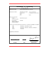
Declaration of Conformity
according to EN 45014
Manufacturer’s Name:
Advanced Digital Information Corporation
Manufacturer’s Address:
10201 Willows Road NE
Redmond, WA
98052
USA
21-23 Av. Saint-Fiacre
F-78100 Saint-Germain-en-Laye
France
declares, that the product:
Product
(Produit, Erzeugnis):
Virtual Library System
Model Number
(Marque Commercial,
Warenbezeichnung):
VLS 4mm
conforms to the following international specifications, as required by 89/336/EEC & 92/31/EEC:
EMI:
EN 50081-1, EN-55022 Class B
EMC:
EN 50082-1, IEC 801-2, IEC 801-3, IEC 801-4
Safety:
EN 60950
Supplementary Information:
Redmond, Washington USA
3-Jan-1996
Project Engineering Mgr
Location
Date
Signature/Title
v
Safety Warnings
Caution
All safety and operating instructions should be read before this product
is operated, and should be retained for future reference. This unit has
been engineered and manufactured to assure your personal safety.
Improper use can result in potential electrical shock or fire hazards. In
order not to defeat the safeguards, observe the following basic rules for
its installation, use and servicing.
1. Heed Warnings - All warnings on the product and in the operating instructions
should be adhered to.
2. Power Source - The product should be connected to a power source only of the
type directed in the operating instructions or as marked on the product.
3. Power Cord Protection - The AC line cord should be routed so that it is not likely
to be walked on or pinched by items placed upon or against it, paying particular
attention to the cord at the wall receptacle, and the point where the cord exits from
the product.
4. Power Switch - The power switch used in this product does not disconnect both
supply conductors when placed in the OFF position. To completely disconnect
power from this product, unplug the AC power cord from the receptacle on the
back of the unit.
5. Servicing - The user should not attempt to service the product beyond that
described in the operating instructions. All other servicing should be referred to
qualified service personnel.
vi
Table of Contents
Copyright Notice................................................................................................................... ii
Copyright Notice (Europe) ...................................................................................................iii
EMI/RFI Compliance........................................................................................................... iv
Safety Warnings .................................................................................................................. vi
Quickstart............................................................................................................................ ix
Chapter 1: Getting Started.................................................................................................... 1
Introduction.............................................................................................................. 2
Requirements............................................................................................................ 2
Unpack and Inspect .................................................................................................. 3
Equipment Description ............................................................................................. 4
The VLS Unit .............................................................................................. 4
Magazine..................................................................................................... 4
Media .......................................................................................................... 5
Cleaning Cassette......................................................................................... 6
System Software....................................................................................................... 6
Preparing the Host Computer System........................................................................ 7
Power Off the Computer .............................................................................. 7
Confirm and/or Install the SCSI Host Interface............................................. 7
Chapter 2: Connecting the VLS............................................................................................ 9
Connecting the Interface Cables.............................................................................. 10
Connecting More Than One VLS............................................................................ 12
Powering on the System.......................................................................................... 13
Installing the Backup Software ............................................................................... 14
Chapter 3: Equipment Description...................................................................................... 15
Front Panel Switches and Indicators........................................................................ 16
Rear Panel Switches and Connectors....................................................................... 18
Menu Items ............................................................................................................ 18
Configuration Menu................................................................................... 20
Buzzer Configuration .................................................................... 20
SCSI ID Config............................................................................. 21
SCSI Parity................................................................................... 22
Off-Line Time ............................................................................... 22
vii
Drive Configuration....................................................................... 23
On-Line Mode............................................................................... 23
Sequential-Access Mode Configuration.......................................... 24
Diagnostics Menu ...................................................................................... 25
Write EEPROM Mode............................................................................... 26
Chapter 4: Operation and Maintenance............................................................................... 27
DDS-2 Media......................................................................................................... 28
Inserting Data Cassettes into the Magazine ............................................................. 29
Inserting the Magazine into the VLS ....................................................................... 31
Loading the Magazine ............................................................................................ 33
Attempting to Load the Magazine with a Cassette Already in Drive......................... 34
Manually Removing a Cassette Loaded in the Drive ................................... 35
Removing the Magazine from the VLS.................................................................... 36
Removing the Magazine while a Cassette is in the Drive ............................. 37
Loading an Individual Cassette ............................................................................... 37
Removing a Cassette from the Magazine................................................................. 39
Storing the Magazine.............................................................................................. 39
Cleaning the Drive Head......................................................................................... 39
Cleaning the Enclosure ........................................................................................... 43
Chapter 5: Troubleshooting and Diagnostics...................................................................... 45
VLS Error Messages .............................................................................................. 46
Error Messages ...................................................................................................... 47
Drive Warning Signals ........................................................................................... 49
Environmental Considerations................................................................................. 52
When You Call ADIC Customer Assistance............................................................ 52
Return for Repair RMA (Return Merchandise Authorization).................................. 54
Appendix A:
Appendix B:
Appendix C:
Appendix D:
Installing the Ferrite Bead .............................................................................. 55
Diagnostics Menu .......................................................................................... 57
Glossary........................................................................................................ 65
Specifications ................................................................................................ 71
Index .................................................................................................................................. 75
viii
Table of Contents
Quickstart
This Section …
❐ provides a quickstart guide for experts who are familiar with
installing computer hardware and software.
ix
Note
DXU F<C XQc RUU^ cXY``UT gYdX dXU C3C9 94 V_b TbYfU 1 cUd Qd ²!³ TbYfU
2 cUd Qd ²"³ Q^T dXU b_R_dYSc cUd Qd ²#³
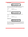
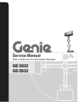
❐ Confirm that power is off and that you have a SCSI interface (either a separate
board as offered by DGLF or integrated on the mother-board) installed in the host
computer. Consult your computer manual.
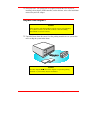
❐ Place the DGLF VLS near the host computer to which it will be connected.
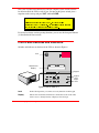
❐ Connect the SCSI interface cable between the SCSI connectors on the computer
and the back of the VLS.
Terminator
SCSI
Interface
Cable
Host Computer
❐ Make sure there is a terminator installed on the last device of the SCSI chain.
x
Quickstart
Note
DGLF bUS_]]U^Tc dXU ecU _V Q^ ²1\d"³ QSdYfU cY^W\U U^TUT
dUb]Y^Qd_b ceSX Qc DGLF `^ &!!!"$ !
❐ Connect the AC power cord first to the VLS and then to the AC outlet. Power on
the VLS. Power on the host computer.
❐ Place the magazine on the carriage by slipping it over the left “magazine position”
pin and then rotating toward the right and pressing into place on the right
“magazine position” pin.
❐ If the application has not already done so, load the magazine by pressing first the
ALT button and then the LOAD button. (If you are in sequential mode, the first
cassette will be inserted in the drive when the load finishes.)
Quickstart
xi
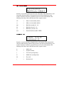
Lock
16-Character
Display
Keypad
9,578$/ /,%5$5< 6<67(0
0(18
$/7
(17(5
(6&
/2$'
81/2$'
0$*$=,1(
/2&.('
'5,9( %
32:(5
'5,9( $
Locked
LED
Power
LED
❐ Install or confirm the backup software (to run the VLS) on the host computer.
❐ Run any diagnostic tests provided with the backup software to make sure the VLS
is communicating correctly with the host computer.
You are now ready to run the VLS at a system level.
xii
Quickstart
Chapter
1
Getting Started
This Chapter …
❐ covers what you need (and what you need to know) to install the
DGLF Virtual Library System. Read this section before you begin
installation.
1
Introduction
The Virtual Library System (VLS) is designed for high-capacity, near and off-line
storage applications, backup, hierarchical storage management (HSM), and
video/design/data file libraries. For the most part, installation is simply a matter of
checking all necessary SCSI connections, installing the software (backup or otherwise)
and applying power. The defaults set at the factory should be sufficient for most
applications.
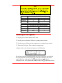
Requirements
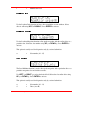
8 .0 in.
20 .3 cm
15 .8 in .
40 .1 cm
1 7.4 in
4 4.2 cm
❐ Space requirements: the VLS has a footprint of 17.4" x 15.8". You must allow
adequate clearance to the rear and bottom to allow air flow and enough room at
the front to open the door which stands 8" high and is hinged at the bottom.
❐ We assume that you are familiar with your computer system. The VLS must be
incorporated into the host computer system. The backup software, SCSI interface
and SCSI interface cable(s) must be purchased separately.
❐ Mode of operation: You must know whether the VLS will be operating in
sequential or random-access mode. This will be determined by the backup
software you use.
2
Getting Started
❐ Necessary tools: No special tools are required to install the VLS. If you are
installing a host adapter (SCSI controller) card at this time, refer to the installation
manual for your host adapter.
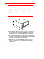
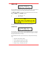
Unpack and Inspect
Caution
If the operating environment differs from the storage environment by
15° C (30° F) or more, let the unit acclimate to the surrounding
environment for at least 12 hours.
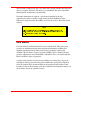
❐ Unpack all items from the carton. Save the packing materials in case you need to
move or ship the system in the future.
a d ic
O NL N
I E
R E SE T
UP
D OW N
M EN U
E N TE R
LE FT
R I GH T
LO C K
P OWE R
Caution
You must ship the DGLF VLS in the original or equivalent packing
materials or your warranty may be invalidated.
Getting Started
3
Equipment Description
The VLS Unit
The DGLF VLS is a fully automated, high performance, high capacity, mass storage
system designed with a removable data cassette magazine. The door can be locked to
deactivate the unit's keypad, assuring only authorized removal of the magazine and
media. In addition, to protect the unit, data and media, the VLS will not operate unless
the door is closed.
Magazine
Note
DGLF cdb_^W\i bUS_]]U^Tc dXQd i_e ecU DGLF Q``b_fUT TQdQWbQTU
]UTYQ _^\i 4_ ^_d QddU]`d d_ ecU QeTY_WbQTU ]UTYQ ceSX ]UTYQ
SQ^ TQ]QWU dXU XUQTc Q^T dQ`U XQ^T\Y^W `Qbdc ° f_YTY^W i_eb
gQbbQ^di
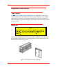
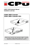
The magazine for the VLS holds fifteen 4mm cassettes. It includes a clear dust cover
to protect the cassettes and for ease of storage. Figure 1 shows a 4mm cassette and a
filled magazine with the cover in place.
Figure 1. VLS Magazine for 4mm Cassettes
4
Getting Started
Media
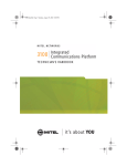
The 4mm VLS uses 4mm DDS data cassettes. Before inserting the cassette into the
magazine check the position of the write-protect switch. Set all switches to the enabled
position – hole closed (refer to Figure 2). (The write-protect switch enables or disables
the ability to write [or delete] files on the data cassette.)
Caution
Only cassettes labeled "DDS" should be used. Never use audio DAT
cassettes, because the media is not certified. Also, DAT cassettes have
a different mechanical specification which can cause them to jam in
the mechanism.
❐ To write-protect the data cassette, move the write-protect switch away from the
edge of the data cassette, as shown in Figure 2. If the hole is open, the cassette is
write protected and cannot be written to (or erased).
❐ To write-enable the data cassette, move the write-protect switch toward the edge
of the data cassette, as shown. If the hole is closed, the data cassette is write
enabled and can be written to or erased. Use a ball-point pen or similar instrument
to set the write-protect switch.
W rite -P ro te c t
S w itch
O pen
(P rotected)
Closed
(U nprotected)
Figure 2. 4mm Cassette Showing Write-Protect Switch
Getting Started
5
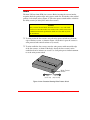
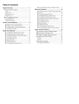
Cleaning Cassette
The tape heads should be cleaned after every 8 to 10 hours of tape motion or when the
Media Caution indication is displayed. A cleaning cassette (ADIC 39-1028-01) is
shipped with your DGLF VLS. Discard it after approximately 20 uses and replace it
with the same or equivalent type cleaning cassette. See Cleaning the Drive Head later
in this manual.
Figure 3. 4mm Cleaning Cassette
System Software
A variety of backup and data storage software is available for use with the VLS.
Please check with DGLF Sales or Customer Assistance if you have a question on the
compatibility of a particular software package.
6
Getting Started
Preparing the Host Computer System
Power Off the Computer
❐ Turn off the power switch.
❐ Unplug the cord from the AC outlet.
Confirm and/or Install the SCSI Host Interface
The VLS must be connected to either an integrated SCSI host or a SCSI interface
(host adapter) card installed in the computer – either directly to the I/O connector on
the card or as part of an existing SCSI chain. The SCSI interface must be installed
before you connect the VLS. Refer to the instructions supplied with your selected
SCSI interface.
Now you are ready to connect the VLS to your host computer. Follow the instructions
provided in the next chapter.
Note
DXU X_cd S_]`edUb cicdU] ^_b]Q\\i Yc dXU cUbfUb
Getting Started
7
Blank Page
8
Getting Started
Chapter
2
Connecting the VLS
This Chapter …
❐ provides instructions for physically connecting your VLS to your
host system.
❐ steps you through the final phase of the installation process.
9
Connecting the Interface Cables
Note
DXU Y^dUbVQSU SQR\Uc ]ecd RU cXYU\TUT °
DGLF SQ^ ce``\i i_e gYdX dXU
S_bbUSd di`Uc
Make sure the interface cable you are using has the appropriate connectors on each
end. If the host computer's SCSI connector is different from that on the VLS, you will
need to obtain a different cable than the one supplied with the unit. Consult your
dealer or DGLF Customer Assistance if you need help. Connect the interface cables as
shown in Figure 4 and explained in the following steps:
❐ Check that the power switches on both the VLS and the host computer are off.
❐ Attach one end of the SCSI interface cable to either connector on the rear of the
VLS. Press firmly and secure the bail locks.
V LS
Term ina to r
H o s t C o m p u te r
SC SI
In terface
Ca ble
Figure 4. Connecting the Interface Cables
10
Connecting the VLS
Note
DXU RQY\ \_S[c Qd R_dX U^Tc _V dXU C3C9 SQR\U ]ecd RU cUSebU\i
VQcdU^UT Y^ _bTUb V_b dXU F<C d_ S_]]e^YSQdU `b_`Ub\i gYdX dXU
S_]`edUb
❐ Plug the other end of the SCSI interface cable into the external connector on the
SCSI port card. Secure firmly.
❐ If this is the only unit you are installing, insert an external terminator plug into the
second SCSI connector at the rear of the VLS. If you plan to connect another unit
on the same SCSI channel, see the next section.
Connecting the VLS
11
Connecting More Than One VLS
If you are connecting additional VLS units on the same SCSI channel, simply attach
each subsequent unit to the previous unit with an interface cable. Make sure all cables
are properly secured. You can attach up to seven devices on each SCSI channel.
2 V L S u n its
(O n sam e
SC SI
Ch annel)
*F errite
B ead
Term inator
SCSI
In terface
C able
I/O
C on necto rs
H o st
C o m p u te r
Figure 5. Cable Diagram for two VLS Units
Note
GXU^ S_^^USdY^W dg_ _b ]_bU F<C e^Ydc d_ Q cY^W\U C3C9 SXQ^^U\ i_e
]ecd Y^cdQ\\ Q VUbbYdU RUQT _^ dXU SQR\U BUVUb d_ 1``U^TYh 1 V_b
TUdQY\c
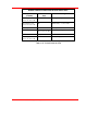
Each VLS unit contains more than one SCSI device and may require more than one
SCSI ID (depending on the mode of use and number of drives). The first chart below
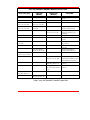
shows various configurations and the number of SCSI IDs required. The second chart
illustrates how many VLS units you can attach to one SCSI channel (if there are no
other devices on the channel).
12
Connecting the VLS
Note
GXU^ S_e^dY^W C3C9 TUfYSUc [UU` Y^ ]Y^T
dXQd Q F<C SQ^ S_^dQY^ e`
d_ dXbUU TUfYSUc 4bYfU 1 4bYfU 2 Q^T dXU b_R_dYSc 4_^d V_bWUd d_
Y^S\eTU Y^ i_eb S_e^d _dXUb TUfYSUc _^ i_eb C3C9 SXQ^^U\ YU Q dQ`U
e^Yd Q^ QTTYdY_^Q\ XQbT TbYfU UdS
Number of SCSI IDs Required
VLS
Sequential Mode
Random Mode
One drive
1
2
Two drives
N/A
3
Maximum VLS units on one Channel
VLS
Sequential Mode
Random Mode
One drive
7
3
Two drives
N/A
2
Powering on the System
❐ Plug the power cord into the back of the VLS.
❐ Plug the power cord from the VLS into a grounded electrical outlet.
❐ Plug the power cord from your host computer into a grounded electrical outlet.
❐ Turn on the VLS power. Turn on the host computer power.
A display similar to the following will appear on the VLS display:
The top line of the LCD is logically divided into a Drive A side (left), and a Drive B
side (right). When the VLS is in the On-Line mode, the LCD displays the current
status of the drives on the top line. The symbol indicates that the drive is
configured, on-line, and is aligned with the Media Picker. The symbol indicates that
Connecting the VLS
13
the drive is configured and on-line, but is not aligned with the Media Picker. The
symbol indicates that there is no configured drive in that position. The in the 5th
character position for each drive indicates that the VLS does not know if a cartridge is
currently loaded in that drive. If the VLS had loaded a cartridge into a drive prior to
shut-down, this character and the one proceeding it would reflect the slot number of
the magazine that the cartridge was loaded from (01 to 15). The 7th character position
may display a symbol, indicating that the drive is actively writing or reading.
The bottom line of the LCD, when the VLS is in the On-Line mode, displays the
characters indicate that the VLS
current status of the magazine. The
does not know the current status of the magazine. This is normal immediately
following power-up. If the magazine had been loaded prior to shut-down, the VLS
would display
when repowered..
You are now ready to install the backup software – if it has not already been installed.
Installing the Backup Software
At this point you need to refer to your software installation guide for instructions on
installing the backup/controlling software for the VLS onto the host computer.
After you have completed installation of the VLS and the backup/controlling software,
make sure that your unit is operating correctly by running any diagnostic test(s)
supplied with the backup software.
14
Connecting the VLS
Chapter
3
Equipment Description
This Chapter …
❐ describes the switches, indicators and connectors on the front and
rear of the VLS.
❐ describes the various functions available via the front panel
buttons.
❐ describes the power-up procedure and messages on the front
panel LED display.
15
Once your VLS has been connected to your host computer system and the software
has been installed, the VLS is ready for use. Just turn on the power switch, place a
magazine on the carriage and press ALT and then LOAD.
Note
DXYc Yc dXU c_VdgQbU dXQd be^c dXU F<C ^_d dXU TQdQ RUY^W
dbQ^cVUbbUT d_ dXU F<C SQccUddUc Dg_ UhQ]`\Uc _V RQS[e` c_VdgQbU
QbU 3XUiU^^Uc 1B3cUbfU Q^T <UWQd_c >UdG_b[Ub
If you need to change certain operating functions, you can use the front panel buttons
(as described in the next section).
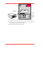
Front Panel Switches and Indicators
Switches and indicators on the front of the VLS are shown in Figure 6.
Lock
16-Character
Display
Keypad
9,578$/ /,%5$5< 6<67(0
0(18
$/7
(17(5
(6&
/2$'
81/2$'
0$*$=,1(
/2&.('
'5,9( %
32:(5
'5,9( $
Locked
LED
Power
LED
Figure 6. Front of ADIC VLS
16
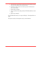
Lock
In the locked position, you cannot access any functions of the keypad.
Display
The two-line 16-character LCD shows current drive status of the VLS,
allows access to change features or displays error messages.
Equipment Description
Power LED
(green)
Lights when power is on.
Locked LED
(green)
Lights when door is locked. The magazine, drive, or keypad cannot be
accessed while the Locked LED is on.
MENU
Press this button to enter or exit Off-line mode menus
ALT
Selects alternate function for another button. For example, press the ALT
button to activate the load function.
button and the UP
Up
Selects previous item or value in the menu.
LOAD
Press the ALT button and then this button to initiate a "load magazine" –
the VLS will check all cassettes in the magazine (making note of empty
spaces) and that all cassettes can be inserted in the drive.
Note
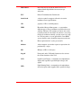
DXU F<C ecUc dXU <?14 Ve^SdY_^ d_ TUdUSd SQccUddUc _b dXU QRcU^SU
_V Q SQccUddU
Down
Selects next item or value in the menu.
UNLOAD
Press the ALT button and then this button to initiate the unload program –
the VLS will return the magazine to the unload position.
Caution
Never attempt to remove a magazine unless it is in the unload position
– you may damage the pick arm.
ENTER
Selects currently displayed item.
ESC
Exits current menu and returns to previous menu.
Left
Scrolls message display to the left or selects previous field on same line.
DRIVE A
Press the ALT button and then this button to select drive A.
Right
Scrolls message display to the right or selects next field on same line.
DRIVE B
Press the ALT button and then this button to select drive B.
Equipment Description
17
Rear Panel Switches and Connectors
Switches and connectors on the rear of the VLS are shown in Figure 7.
SC SI I/O
C onnectors
Fan Filter
R ear
A ccess Panel
A C P ow er Connector
and Pow er Sw itch
Figure 7. Back of ADIC VLS
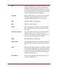
Power Switch
Turns on the AC power to the VLS.
AC Power Connector
Plug the VLS AC power cord into this connector.
SCSI I/O Connectors
Connections for the interface cable which connects the
VLS to the computer, to other VLS units and/or to other
devices on the SCSI channel.
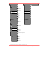
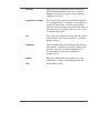
Menu Items
The menus and mode shown at the top of the following diagram are selections
available from the Main Menu. When you choose one of the Main Menu items, a set
of options appears; these options are listed below the Main Menu selections. If an
option has sub-options, these sub-options are listed below and to the right of the
option.
18
Equipment Description
Configuration Menu
Diagnostics Menu
Buzzer Configuration
Error Counters
ErrAlarm
Yes/No
Event Counters
Kybd
Yes/No
Operation Log
SCSI ID Config
Firmware Revision
Drive B
(0-7)
Serial Number
Drive A
(0-7)
Position Drive
AC
(0-7)
Position Magazine
SCSI Parity
Parity Check
Load Medium
Yes/No
Off-Line Time
Max time
Write EEPROM Mode
Unload Medium
Unload Drives
1-99 min
Drive Configuration
Drv A
Yes/No
Drv B
Yes/No
On-Line Mode*
Random / Sequential
Sequential Mode Cfg*
First
(0-11)
Last
(0-11)
Loopback
Yes/No
*Available only when VLS is configured as a single-drive unit.
Equipment Description
19
To access the Off-Line menu, press the MENU button. The display will appear as
follows:
Use the UP or DOWN buttons to scroll through the menu. Press ENTER to
select a displayed item. Use the RIGHT
or LEFT
buttons to scroll through
fields on the same line.
To exit the Off-Line menu press the MENU button.
Configuration Menu
The Configuration Menu allows you to select the following operating parameters:
•
Buzzer Configuration
•
SCSI ID Configuration
•
SCSI Parity
•
Off-Line Time
•
Drive Configuration
•
On-Line Mode (Single Drive models only)
•
Sequential-Access Mode Configuration (Single Drive models only)
Buzzer Configuration
Enables/disables the sounding of an alarm when an error message is displayed.
Enables/disables the beep sound when you press a keypad button.
When you select the Buzzer Configuration option a display similar to the following
appears:
20
Equipment Description
To enable the error alarm use the LEFT
button to select the ErrAlarm field. Use
or DOWN to select "Y" to enable alarm or "N" to disable alarm. When
UP
Error Alarm mode is enabled, a continuous alarm tone will sound in the event of an
error message. The alarm will sound until the condition that caused the error has been
removed or any key is pressed. To clear an error message from the display, press ALT
and ENTER.
If you wish to change the status of the keyboard beep, use the RIGHT button to
select the Kybd field. Use UP
or DOWN to select "Y" to enable a beep when
you press a button or "N" to disable the beep. Press ENTER to make the changes
effective or press ESC to return to previous menu item.
Note
2ejjUb 3_^VYWebQdY_^ TUVQe\d* 5bb 1\Qb]* > ;iRT* I
SCSI ID Config
Lets you select the SCSI ID for drive A, drive B and the robotics on the VLS.
Use LEFT
or RIGHT to select the desired field. DA is Drive A, DB is Drive B
and DOWN to
and AC is the robotic unit (autochanger) on the VLS. Use UP
scroll to the desired ID for that particular element. Press ENTER.
Notes
C3C9 94 SXQ^WUc U^dUbUT T_ ^_d dQ[U UVVUSd e^dY\ i_e SiS\U `_gUb _^
dXU F<C e^Yd
C3C9 94 3_^VYWebQdY_^ TUVQe\d* 4bYfU 1*! 4bYfU 2*" 13*#
CUU dXU cUSdY_^ Y^ 3XQ`dUb " ^_dY^W dXU C3C9 94c ^UUTUT V_b dXU F<C
Equipment Description
21
SCSI Parity
Lets you enable or disable the reporting of SCSI parity. Press ENTER to access this
function.
Use UP or DOWN to select "Y" to enable the reporting of parity check or "N"
to disable the reporting of parity check. Press ENTER to activate the change.
Note
C3C9 @QbYdi TUVQe\d* @QbYdi 3XUS[* >
Off-Line Time
Lets you set the number of minutes the VLS will remain in the Off-Line mode. If
someone leaves the VLS in an Off-Line mode, after the pre-set number of minutes the
VLS will automatically return On-Line. This assures that your automatic backup will
be done even if the VLS has accidentally been left Off-Line.
Use UP or DOWN to select the number of minutes you wish the VLS to remain
Off-Line. Press ENTER to execute the change.
Note
?VV\Y^U dY]U TUVQe\d* % ]Y^edUc
22
Equipment Description
Drive Configuration
This function lets you enable or disable which drives are on-line.
Use LEFT or RIGHT to select the drive you wish to change. Use UP or
DOWN to select "Y" to put the drive on-line or "N" to disable the drive. If you
have only one drive installed, you cannot access the Drv B field.
Note
1 TYcQR\UT TbYfU Yc cdY\\ S_^^USdUT d_ dXU C3C9 Rec Q^T gY\\ bUc`_^T d_
dXU \Qcd QTTbUcc cUddY^W D_ QccebU dXQd QTTbUcc SXQ^WUc Q^T TbYfU
S_^VYWebQdY_^ SXQ^WUc QbU Ve\\i Y^YdYQdUT i_e ]ecd SiS\U `_gUb
Disabling both drives is not allowed (setting "N" in Drv A or Drv B field
automatically places "Y" in the other field).
Note
4bYfU 3_^VYWebQdY_^ TUVQe\d cUddY^W Yc I V_b UQSX Y^cdQ\\UT TbYfU
On-Line Mode
Lets you select random-access or sequential-access operating mode.
When used in random-access mode, the VLS allows software selection of any cassette
in the magazine in any order. You can logically divide cassette usage to satisfy
particular data storage needs. For example, you can assign one or more cassettes to
specific data functions (such as certain directories or network servers), or you can
assign specific cassettes to individual users.
Equipment Description
23
Note
9V i_e XQfU R_dX TbYfUc _^ \Y^U i_e gY\\ ^_d RU QR\U d_ QSSUcc dXYc
Ve^SdY_^ DXU c_VdgQbU i_e ecU gYdX dXU F<C TUdUb]Y^Uc gXUdXUb i_e
SQ^ _`UbQdU dXU F<C Y^ cUaeU^dYQ\ Q^T_b bQ^T_] ]_TU
DGLF's VLS can also be used as a stacker in sequential-access mode if your software
does not support the random-access mode function.
Use UP
or DOWN
to select "random" or "sequential".
Note
?`UbQdY^W =_TU TUVQe\d cUddY^W Yc BQ^T_]³
Sequential-Access Mode Configuration
If you are using Sequential-Access Mode, this option lets you select which cassettes
the drive will write to, and whether or not you wish the drive to start again at the
beginning after the last cassette has been written to.
Note
9V i_e XQfU Q TeQ\TbYfU cicdU] Q^T R_dX TbYfUc QbU _^ \Y^U i_e gY\\ ^_d
RU QR\U d_ QSSUcc dXYc Ve^SdY_^
to select the item you wish to change. "F" is the number
Use LEFT or RIGHT
of the First cassette you wish the VLS to insert into the drive. "L" is the number of the
Last cassette you wish the VLS to insert into the drive.
24
Equipment Description
The Loopback (LPBK) mode determines what happens when the last cassette has been
filled. If you select "Y" for "Lpbk" the designated first cassette will be loaded into the
tape drive after the last cassette has been filled and ejected. If you select "N" an error
message will be issued and the backup will stop.
Note
4UVQe\d cUddY^W Yc 6*
! <* !! <`R[* I
Diagnostics Menu
The following functions are available under the Diagnostics Menu:
•
Error Counters
•
Event Counters
•
Operation Log
•
F/W Revision
•
Serial Number
•
Position Drive
•
Position Magazine
•
Load Medium
•
Unload Medium
•
Unload Drives
For information on these options, refer to Appendix B.
Warning
We highly recommend that these diagnostic functions be used only by
a qualified service technician (or on the instruction of a qualified
technician). Some of these functions assume that the unit has been set
up correctly and thus many of the normal built-in safety checks are
turned off. Misusing these diagnostic functions without the normal
safety checks could result in improper operation (or even damage to
media or VLS).
Equipment Description
25
Write EEPROM Mode
The Write EEPROM Mode is used whenever you upgrade the VLS firmware. Refer to
Appendix C in this manual for additional information.
26
Equipment Description
Chapter
4
Operation and Maintenance
This Chapter …
❐ describes normal operation features of the VLS
❐ provides details on the media and magazine
❐ explains normal maintenance procedures
27
The VLS unit is composed of one or two DAT drives and the robotics that control the
drive(s), magazine and media. The drive(s) are unmodified. The drive status LEDs
function per the manufacturer’s specifications.
No routine maintenance is required – apart from cleaning the heads after
approximately each 8 to 10 hours of tape motion or when the Media Caution
indication is displayed on the drive LEDs (see Cleaning the Drive Head later in this
manual).
Note
CY^SU dXU TbYfU cdQdec <54c QbU \_SQdUT _^ dXU \_gUb Vb_^d _V dXU
TbYfU d_ cUU dXU] i_e ]ecd RU UiU\UfU\ gYdX dXU WbY``Ub Qb] _V dXU
F<C <__[ RUi_^T dXU Qb] d_ dXU TbYfU
DDS Media
Use only industry-standard 4mm DAT cassettes with the VLS. These data-grade
cassettes are manufactured under more stringent environmental, reliability and
durability specifications than audio-grade cassettes, producing superior data
reliability. The 125-meter cassettes, used only in DDS-3 drives, and the 120-meter
cassettes, which can be used in both DDS-3 and DDS-2 drives, are marked with the
DDS-3 and DDS-2 logos, respectively.
A write-protect switch is used to prevent recording over existing data. To prevent
recording or deleting, place the write-protect switch to the open position. The drive
senses the position of the switch and will not allow writing in this position. When
inserting cassettes in the magazine, place the switch in the closed position (unless you
do not wish to record on a specific cassette).
28
Operation and Maintenance
Write-Protect Switch
Closed (Unprotected)
Open (Protected)
Inserting Data Cassettes into the Magazine
The magazine for the 4mm VLS holds fifteen 4mm cassettes. It includes a clear dust
cover to protect the cassettes and for easy storage. See Figure 8. Insert each cassette
into a slot of the magazine making sure that the write-protect tab is on the top and the
cassette faces toward you when the magazine is loaded onto the carriage of the VLS
(as illustrated).
A spring holds each cassette in place even if the magazine is turned upside down.
Note
DGLF cdb_^W\i bUS_]]U^Tc dXQd i_e ecU DGLF-bUS_]]U^TUT TQdQ
WbQTU ]UTYQ _^\i 4_ ^_d QddU]`d d_ ecU QeTY_WbQTU ]UTYQ ceSX
]UTYQ SQ^ TQ]QWU dXU XUQTc Q^T dQ`U XQ^T\Y^W `Qbdc ° f_YTY^W i_eb
gQbbQ^di
Operation and Maintenance
29
M a g a zin e C o ve r
W rite -P ro te ct S w itc h
D a ta C a s se tte s
M a g a z in e
O p e n sid e o f
m a g a zin e
(to w a rd s V L S )
C lo se d sid e
o f m a g a z in e
Figure 8. VLS Magazine
The open side of the magazine faces the VLS. Make sure each cassette touches the
bottom floor of the magazine.
Do not use wrap-around labels on the individual cassettes. Most labels use a
removable adhesive and have a tendency to curl or tear after multiple uses. This can
jam the movement of the VLS. Place labels only in the space provided on the cassette.
Note the following:
❐ Store magazines (and data cassettes) in a dry, cool environment. Keep the dust
cover on the magazine.
❐ Never reset or power down your computer or VLS while a function is in process
or a tape is moving. In addition to getting tape with missing or corrupted data, you
may also get tape run-on within the drive (a condition that can produce internal
contamination requiring factory cleaning).
❐ If a power outage occurs during a back-up sequence, restart your backup from the
beginning.
30
Operation and Maintenance
Inserting the Magazine into the VLS
Note
4_ ^_d QddU]`d d_ `\QSU Q S_fUbUT ]QWQjY^U _^d_ dXU F<C SQbbYQWU
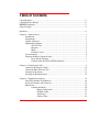
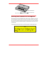
❐ Remove the magazine cover. You can remove the cover by pressing the middle of
both ends (where it is labeled PUSH) and lifting up (see Figure 9).
Figure 9. Removing the Magazine Cover
❐ Open the VLS door.
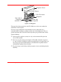
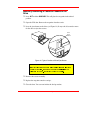
❐ Holding the magazine by the thumbhole handle, and at a 45° angle to the carriage,
slip the magazine onto the left side of the carriage, over the magazine position pin
(see Figure 10).
Operation and Maintenance
31
639181
Left "magazine
position pin"
Figure 10. Placing the Magazine onto the VLS
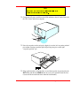
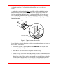
❐ Push the right side of the magazine over the right hand magazine position pin until
you hear a click. See Figure 11.
Note
I_e ]Qi ^UUT d_ Q``\i T_g^gQbT `bUccebU Qc i_e c\Y` dXU ]QWQjY^U
_fUb dXU bYWXd ]QWQjY^U `Y^ Q^T dXU^ `bUcc dXU ]QWQjY^U Y^d_ `\QSU
gYdX i_eb Y^TUh VY^WUb
Figure 11. Pushing the Magazine in Place
32
Operation and Maintenance
The magazine will snap into place. If you don't hear a click, make sure that the slot on
the right side of the magazine has slipped around its magazine position pin and is not
just sitting on top of it. The magazine will not load correctly in this position.
Loading the Magazine
Once you have placed the magazine on the carriage, the VLS must initiate a loading
process. During this procedure the VLS checks and maps the position of each cassette
and makes sure that all cassettes are inserted into the magazine correctly. If you are
using the sequential mode the VLS inserts the first cassette into the drive.
Note
DXU T__b ]ecd RU S\_cUT RUV_bU dXU <?14 _b E><?14 Ve^SdY_^c gY\\
QSdYfQdU
❐ Make sure the magazine is placed correctly on the carriage.
❐ Close the door and press ALT and then LOAD. The VLS will initiate the load
magazine procedure.
Note
9^ dXU cUaeU^dYQ\ ]_TU YV i_e `bUcc
UNLOAD RUV_bU dXU F<C XQc
VY^YcXUT \_QTY^W dXU ]QWQjY^U dXU b_R_dYSc gY\\ VY^YcX ]Q``Y^W Q^T
SXUS[Y^W dXU SQccUddUc Q^T dXU^ ]_fU dXU ]QWQjY^U d_ dXU e^\_QT
`_cYdY_^ dXU VQb bYWXd gYdX_ed Y^cUbdY^W Q SQccUddU Y^d_ dXU TbYfU
9^ bQ^T_] ]_TU YV i_e `bUcc
UNLOAD RUV_bU dXU F<C VY^YcXUc
\_QTY^W dXU ]QWQjY^U Yd gY\\ XQfU ^_ UVVUSd
Operation and Maintenance
33
Attempting to Load the Magazine with a
Cassette Already in Drive
Random Mode: If the cassette was loaded manually, it must be unloaded manually –
before you attempt to have the VLS load the magazine. Refer to the next section for
manual removal of a cassette. If the VLS robotics was used to load the cassette via
applications software, attempting to "load magazine" from the keyboard will fail – the
unit will remain on-line.
Sequential Mode: If the cassette was loaded manually, it must be unloaded manually
– before you attempt to have the VLS load the magazine. Refer to the next section for
manual removal of a cassette. If the VLS robotics was used to load the cassette, the
VLS will remember and not allow a "load magazine" from the keyboard. Press ALT
and then ENTER to bring the VLS back on-line.
34
Operation and Maintenance
Manually Removing a Cassette Loaded in the
Drive
❐ Press ALT and then UNLOAD. This will place the magazine in the unload
position.
❐ Open the VLS door. Remove the magazine from the carrier.
❐ Press the eject button on the drive (see Figure 12). It may take 30 seconds or more
for the drive to eject the cassette.
D rive
E je ct
B u tton
Figure 12. Typical Position of Drive Eject Button.
Note
CY^SU dXU 4bYfU 5ZUSd 2edd_^ Q^T 4bYfU GQb^Y^W <YWXdc QbU \_SQdUT _^
dXU Vb_^d _V dXU TbYfU d_ cUU dXU] i_e ]ecd RU UiU\UfU\ gYdX dXU
WbY``Ub Qb] _V dXU F<C <__[ RUi_^T dXU Qb] d_ dXU TbYfU
❐ Remove the cassette manually.
❐ Replace the magazine onto the carriage.
❐ Close the door. You can now initiate the load procedure.
Operation and Maintenance
35
Removing the Magazine from the VLS
Before physically removing the magazine from the carrier, you must first initiate the
UNLOAD procedure.
❐ Make sure there is no cassette in the drive. If there is, go to the next procedure,
Removing the Magazine while a Cassette is in Drive
Note
I_e SQ^^_d Y^YdYQdU Q^ E><?14 _b bU]_fU dXU ]QWQjY^U YV dXU T__b Yc
\_S[UT GXU^ dXU <_S[UT \YWXd Yc _^ dXU F<C YW^_bUc dXU <?14 Q^T
E><?14 Redd_^c
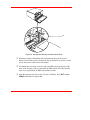
❐ Press ALT and then UNLOAD and wait until the unload procedure is finished. (If
the carriage is not in the unload position, it will move to the right. In addition, the
grippers on the pick arm will close.)Press the Magazine Release on the carriage.
See Figure 13. The magazine will release from the holding pins.
M aga zine
R elease
C atch
Figure 13. The Magazine Release
❐ Grab the thumb handle on the magazine and pull the right side of the magazine
toward you. The magazine will come out at a 30-40 degree angle.
36
Operation and Maintenance
❐ Place the transparent cover over the magazine and store the unit in a cool, dry
place.
Note
=Q[U cebU i_e XQfU \QRU\UT UQSX SQccUddU Qc d_ ]QWQjY^U Q^T c\_d
^e]RUb 9V i_e Tb_` dXU ]QWQjY^U gYdX_ed dXU S_fUb _^ dXU SQccUddUc
gY\\ VQ\\ _ed
Removing the Magazine while a Cassette is in
the Drive
If you wish to remove the magazine but there is a cassette in the drive, do the
following:
❐ Open the VLS door.
❐ Press the eject button on the drive (see Figure 12).
❐ Close the door of the VLS. It will take about 30 seconds for the drive to unload
the tape.
❐ Press ALT and then UNLOAD. The arm will return the cassette to the magazine
slot and the VLS will move the magazine to the unload position.
❐ Remove the magazine as noted earlier.
Loading an Individual Cassette
If for some reason you need to use a single cassette, you can load it manually (this
operation is the same as loading a cleaning cassette).
❐ Unload the magazine by pressing ALT and then UNLOAD. The magazine will
move completely to the right.
❐ Open the door and remove the magazine from the carriage. (See previous
instructions).
Operation and Maintenance
37
❐ Insert the cassette into the drive opening with the label side to your left and the
write-protect switch positioned down. Apply steady pressure on the back of the
cassette until the autoloading mechanism takes the cassette and loads it into the
drive. The cassette is now in a semi-loaded state. If the humidity level is
acceptable, the drive threads the tape, initiates a load sequence and goes on-line.
The drive will take approximately 20 seconds to load the cassette.
Note
9V dXU Xe]YTYdi _^ dXU Y^dUb^Q\ XUQTTbe] Yc UhSUccYfU dXU SQccUddU
gY\\ ^_d RU QSSU`dUT
9V i_e cX_e\T UfUb Uh`UbYU^SU dXYc S_^TYdY_^ Q\\_g dXU cicdU] d_
cdQRY\YjU d_ dXU cebb_e^TY^W dU]`UbQdebU Q^T Xe]YTYdi Q^T dbi QWQY^
❐ Close the door and initiate desired program.
❐ If the drive does not eject the cassette when the program is finished, open the VLS
door (the gripper arm should still be fully extended) and press the drive eject
button (refer back to Figure 12 if necessary). It will take about 30 seconds for the
drive to eject the cassette.
If the normal eject procedure fails to eject a cassette, a Power Eject can be initiated.
Press and hold the drive’s Eject button. The upper LED (on the drive) will begin
flashing amber, as it does during a normal Eject cycle. Holding down the Eject button
for 10 seconds will initiate a Power Eject cycle. The cassette will be ejected
immediately. Using the Power Eject function may cause a tape to be generated that
does not conform to the format standard. After the cassette is ejected, the drive will
reset.
Warning
Power Eject should only be used as a last resort in case of an apparent
drive failure, or if there is no other way to eject a cassette.
38
Operation and Maintenance
Removing a Cassette from the Magazine
The data cassettes easily slip into and out of the slots of the magazine. To remove a
cassette, simply grasp it with two fingers and pull up. Make sure each cassette is
labeled so you know the contents (and where it belongs in the magazine sequence).
Storing the Magazine
Store magazines in a dry, cool environment. Always keep the dust cover on the
magazine.
The removable magazine allows for long-term archiving or off-site safety storage of
groups of data.
You can duplex multiple changers so your system can mirror data backups on each
separate unit. With duplexing you have real time data assurance and the ability to
remove one magazine set for off-site storage while the other remains for on-line data
access.
Cleaning the Drive Head
Caution
Using cloth swabs, cotton swabs, cleaning agents, or unapproved
cleaning cassettes will void the warranty. Use only an DGLF
recommended cleaning cassette. Audio DAT cleaning cassettes do not
have the proper ID hole configuration to initiate the cleaning cycle:
their use will cause excessive head-wear (voiding the warranty).
To prevent contamination of the drive and damage to the heads, do not use the
cleaning cassette for more than the number of cleaning cycles specified on the cassette
label. Discard the cleaning cassette after you have used it the specified number of
cleaning cycles. Do not attempt to rewind the material in the cleaning cassette and
reuse it.
Operation and Maintenance
39
Clean the drive head and tape path after every 8-10 tape motion hours (about once a
week under typical use). You should also clean after the first use of a new tape
cassette.
As an absolute visual reminder, the drive status LEDs will flash the Media Caution
indication during cassette load/unload operations after approximately 24 hours of
head-tape motion since the last cleaning. To see the status LEDs, the magazine must
be in the unloaded position and you must look at the drive (see Figure 13). We urge
you to clean the drive as soon as possible after the LEDs begin flashing the Media
Caution indication.
D rive Status LE Ds
Figure 13. Typical Position of Drive LEDs
Please follow these cleaning directions carefully to assure that no damage will occur to
the tape drive, VLS or media.
❐ Unload the magazine by pressing ALT and then UNLOAD. The magazine will
move completely to the right .
❐ Open the VLS door and remove the magazine from the carriage.
❐ Check the usage record on the label of the cleaning cassette to make sure that there
is at least one cleaning cycle remaining. If there are no cleaning cycles remaining,
discard the cleaning cassette and use a new one. If you attempt to insert a cleaning
cassette which is fully used, the drive will eject the cassette immediately and will
not reset the internal 24-hour cleaning timer. Both drive LEDs will continue to
40
Operation and Maintenance
flash amber during cassette load/unload operations. Figure 14 shows a sample
cleaning cassette with the label on which to write the date of each use.
Figure 14. Representative Cleaning Cassette
Caution
DO not attempt to RE-USE or REWIND the cleaning cassette after all
the cleaning cycles (approx. 20) have been used.
❐ Insert the cleaning cassette into the drive opening (see Figure 15). The drive will
load the cassette and automatically begin the cleaning process. The cleaning cycle
may take from 2 to 3 minutes. The media status LED will flash amber during the
entire cleaning cycle.
Operation and Maintenance
41
Figure 15. Inserting the Cleaning Cassette into the Drive.
❐ When the cleaning is finished the drive will automatically eject the cassette.
Remove the cleaning cassette and write the date on the label so you have a record
of how many times it has been used and when.
❐ To confirm that a cleaning was done, look at the LEDs on the front panel of the
drive. If the cleaning cycle was successful, the LEDs will be off. If the cleaning
cycle was not performed, the LEDs will continue to flash.
❐ Place the magazine onto the carriage. Close the VLS door. Press ALT and then
LOAD to initiate the load procedure.
42
Operation and Maintenance
Caution
Cleaning cassettes are considerably more abrasive to the drive's
recording heads than standard data cassettes. Usage should be kept
within the recommended limits, or the warranty may not be applicable
to the affected equipment.
The VLS is once again ready for use.
Caution
If you encounter a hard error during normal operation, first try a new
4mm data cassette. If this solves the problem, continue on with the
new cassette.
If the symptom persists, try one cleaning cycle with the cleaning
cassette. If this does not resolve the problem, we recommend that you
do NOT use the cleaning cassette again – instead, call the DGLF’s
Customer Assistance group.
Cleaning the Enclosure
The outside of the enclosure can be cleaned with a damp towel. If you use a liquid allpurpose cleaner, apply it to the towel. Do not directly spray the enclosure.
Operation and Maintenance
43
Blank Page
44
Operation and Maintenance
Chapter
5
Troubleshooting
and Diagnostics
This Chapter …
❐ contains some general suggestions to aid you in solving problems
– should you ever run into them.
❐ includes information on error codes and the built-in diagnostics.
45
VLS Error Messages
If any component of the VLS is not communicating correctly, a warning message will
appear on the front display.
A list of error messages in included on the following page. If the error you see is not
on this list, please call DGLF Customer Assistance.
In all cases, after removing the cause of the problem (or if you can't find a cause) push
MENU to return the VLS to the on-line condition.
f the error message is not listed, try to return to the on-line mode by pressing ALT
and/or ENTER. If that does not work or if you get the error again, call DGLF
Customer Assistance and be prepared to tell them what the error message is – and
what the conditions are.
46
Troubleshooting and Diagnostics
Error Messages
Note
C_]U _b Q\\ _V dXU Ubb_b ]UccQWUc ]Qi bUce\d Vb_] _^U _b ]_bU
S_^TYdY_^c DXU TUVY^YdY_^ WYfU^ Yc V_b Q cY^W\U S_^TYdY_^ _^\i 9V i_e
RU\YUfU dXQd dXU S_^TYdY_^ gXYSX SQecUT i_eb Ubb_b ]UccQWU Yc _dXUb
dXQ^ dXU TUVY^YdY_^ `\UQcU SQ\\
DGLF 3ecd_]Ub 1ccYcdQ^SU Qd* "
&
((#$#%'
Error Name
Description
Source location empty
The source location was empty when the VLS attempted to pick
a cartridge from it.
Destination location full
The destination location was full when the VLS attempted to
place a cartridge in it.
Mag unload disabled by
software
The application has issued the SCSI PREVENT/ALLOW
MEDIA REMOVAL command, preventing the magazine from
being unloaded.
Can’t unload, media in
drive
The VLS will unload the magazine only if all drives are empty.
Drive failed to eject
media
The VLS attempted to return a cartridge to a magazine slot, but
the drive had not previously ejected it.
Unexpected Gripper
Arm Sensor break
The VLS sensed that the Gripper Arm Sensor was blocked
when it should not have been.
Unexpected Magazine
Sensor break
The VLS sensed that the Magazine Sensor was blocked when it
should not have been.
No Gripper Arm Sensor
break
The VLS sensed that the Gripper Arm Sensor was not blocked
when it should have been.
No Magazine Sensor
break
The VLS sensed that the Magazine Sensor was not blocked
when it should have been.
Unexpected Medium
Sensor break
The VLS sensed that the Medium Sensor was blocked when it
should not have been.
Unable to return
medium to slot
The VLS attempted to return a cartridge to a magazine slot but
failed, possibly due to a magazine positioning error.
Troubleshooting and Diagnostics
47
Error Name
Description
Unable to load medium
in drive
The VLS attempted to load a cartridge into a drive but failed,
possibly due to a drive positioning error.
Door has been opened
The front door of the VLS had been opened, but is now closed.
Door is open
The front door of the VLS is open. This error will appear
whenever the front door is opened while power is on.
Operation disabled by
keyboard lockout
Whenever the front panel lock is engaged, the keypad is
disabled, disabling any off-line operations.
All configured drives are The VLS received a command (through SCSI, or the front panel
empty
keypad) to unload medium from a drive, but, since the VLS had
not previously loaded a cartridge, the drives are empty.
Slot not empty, can’t
unload drive
A cartridge is occupying the magazine slot currently aligned
with the drive, and the VLS cannot place the cartridge ejected
by the drive into this slot.
SCSI RESET
OCCURRED
A SCSI RESET has occurred, coming from either the SCSI bus,
or from the front panel keypad.
Drive positioning timeout
The drive shuttle failed to position correctly in the allowed time.
Medium incorrectly
oriented
The cartridge is incorrectly oriented in the magazine. This can
occur when the VLS attempts to load the magazine.
Flash RAM erase failure The VLS could not successfully erase the Flash RAM during the
firmware download process.
48
Flash RAM write failure
The VLS could not successfully write to the Flash RAM during
the firmware download process.
NV-RAM selection
failure
The VLS could not successfully select a particular area of the
NV-RAM.
NV-RAM write failure
The VLS could not successfully write to the NV-RAM.
Boot ROM checksum
failure
The checksum of the boot code in the Boot ROM is incorrect.
Unknown error code
XXh
An unknown error has occurred.
Troubleshooting and Diagnostics
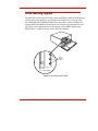
Drive Warning Signals
The 4mm drives used in the VLS employ front panel LEDs to indicate SCSI interface
activity, drive fault conditions, and cartridge status. Figure 16 is a close-up of the
Sony SDT-5000 (SDT-7000/SDT-9000 are the same) drive and the location of the
warning LEDs. The LEDs on all other drives are located in approximately the same
place. Refer to the following tables for descriptions of the methods employed by
different drives to indicate activity, status, and fault conditions.
D riv e
S ta tu s
LEDs
S on y S D T -5 00 0
Figure 16. VLS Drive Status LEDs
Troubleshooting and Diagnostics
49
Hewlett Packard C1533A/C1537A Drive Status LEDs
Tape LED
(bottom)
Clean LED
(top)
Meaning
Flashing green
(½ sec on, ½ sec off)
Off
Cartridge activity — load or unload
Fast flashing green
(¼ sec on, ¼ sec off)
Off
SCSI activity — read or write
Steady green
Off
Off
Flashing amber
(½ sec on, ½ sec off)
Cartridge loaded, drive online
Media Caution Signal
Off
Flashing green
(½ sec on, ½ sec off)
Steady amber
Off
Drive fault
Self-test in progress
Table 3. HP C1533A/C1537A LEDs
50
Troubleshooting and Diagnostics
Sony SDT-5000/SDT-7000/SDT-9000 Drive Status LEDs
Busy LED (Top)
Tape LED
(Middle)
Status LED
(Bottom)
Off
Off
Off
On
Fast flashing
(¼ sec on, ¼ sec off)
Fast flashing
(¼ sec on, ¼ sec off)
Off
Off
Fast flashing
(¼ sec on, ¼ sec off)
Fast flashing (¼ sec on,
¼ sec off)
On
Off
Off
Off
On
On
On
Off
Off
Fast flashing (¼ sec on,
¼ sec off)
*
On
Off
On
On
*
Long, slow flashing
(3½ sec on, ½ sec off)
*
*
*
Long, slow flashing
(3½ sec on, ½ sec off)
*
*
*
*
Flashes once for ¼ sec
then stays off for 1 sec
*
*
Flashes once for ¼ sec
then stays off for 1 sec
Flashes twice once for
¼ sec then stays off for
1 sec
*
Long, slow flashing
(3½ sec on, ½ sec off)
*
Flashes once for ¼ sec
then stays off for 1 sec
On
Fast flashing
(¼ sec on, ¼ sec off)
*
*
MEANING
No cartridge present/no
activity
SCSI activity — read or write
Drive loading/unloading
Drive loading/unloading with
cartridge write protected
Cleaning cartridge at end of
media (no cleaning cycles
remaining)
Cartridge loaded/no activity
Cartridge loaded/SCSI
activity
Cartridge loaded/SCSI and
drive activity
Cartridge loaded/write
protected
Media Caution Signal —
excessive errors detected
High humidity detected
Media Caution Signal —
predetermined number of tape
head motion hours reached
Drive mechanical failure
detected
Drive circuitry failure
detected
Waiting for reset
Waiting for eject
Table 4. Sony SDT-5000/SDT-7000/SDT-9000 LEDs
Troubleshooting and Diagnostics
51
Environmental Considerations
For best performance of your VLS, please observe the following guidelines:
❐ If you expose cassettes to temperatures outside the operating limits – 40-113°F (540°C) – stabilize them by leaving the cassettes in the operating temperature for a
minimum of two hours before you use them.
❐ Avoid temperature problems by ensuring that the VLS's side and rear are not
obstructed so that the drive has adequate ventilation.
❐ Position the VLS where the temperature is relatively stable (i.e., away from open
windows, fan heaters, and doors).
❐ Avoid leaving cassettes in severe temperature conditions, for example, in a car
standing in bright sunlight.
❐ Avoid transferring data (reading from and writing to cassettes) when the
temperature is changing by more than 15°F (10°C) per hour.
When You Call DGLF Customer Assistance
Before calling DGLF Customer Assistance, follow these steps – which will help you
take full advantage of your call:
❐ Review all documentation carefully. (Experience has demonstrated that most
questions are answered in your documentation.)
❐ Be prepared to explain whether the software or hardware has worked properly at
anytime in the past. Have you changed anything recently?
❐ Pinpoint the exact location of your problem, if possible. Note the steps that led to
the problem. Are you able to duplicate the same problem or is it a one-time occurrence?
❐ Note any error messages displayed on your PC screen or file server. Write down
the exact error message.
52
Troubleshooting and Diagnostics
❐ If at all possible, call while at your computer, with DGLF 's system installed and
turned on.
❐ If running on a network, have all relevant information available (i.e. type, version
#, network hardware, etc.).
Be prepared to provide:
•
Your name and your Company’s name
•
Model number
•
Serial number of unit (located on the rear face by the power switch)
•
Software version numbers
– device driver
– archive/restore
•
Hardware configuration, including firmware version, date and number
•
Type of PC, DOS version, clock speed, RAM, network type, network version,
and any special boards installed
•
A brief description of the problem
•
Where you purchased the DGLF system
Having this information available when you call for customer assistance will enable
DGLF to resolve your problem in the most efficient manner possible.
Note
3Q\\ DGLF 3ecd_]Ub 1ccYcdQ^SU Qd* "
9V i_e gYcX i_e ]Qi S_^dQSd
DGLF 22C Qd* "
& ((#$#%'
DGLF 3ecd_]Ub CUbfYSU dXb_eWX dXU
& ((##"!! _b Ri \UQfY^W 9^dUb^Ud 5]QY\ Qd*
ce``_bd0QTYSS_]
Troubleshooting and Diagnostics
53
Return for Repair RMA (Return Merchandise
Authorization)
When you and DGLF Customer Assistance have determined that you need an RMA
number (see previous section When You Call DGLF Customer Assistance). be prepared
with the following information:
•
Model number, serial number, and a brief, descriptive explanation of the
problem.
•
Complete address information (be sure you give any mail stops or special
codes at the time the RMA is issued).
•
If the item is NOT in warranty, you will be charged for the repairs. Therefore,
the Customer Assistance personnel will need a P.O. number at the time the
RMA number is issued. Until credit information can be obtained by our
accounting department, the system may be shipped back COD to first-time
customers.
•
It is also necessary to send the complete system, including the SCSI interface
card/controller, interface cables, and the unit. Problems may have been caused
by a defective external component and/or the drive itself.
Current labor rates will be quoted at the time the RMA is issued.
Loaner or replacement systems are generally NOT available. In extreme
circumstances, they may be arranged for, depending on the nature of the problem and
past history with the customer.
Keep the RMA number as a reference if you call to check on the status of an open
RMA. It MUST also be written on the outside of the package for identification
purposes.
Note
6_\\_gY^W dXYc B=1 `b_SUTebU gY\\ Uh`UTYdU XQ^T\Y^W bU`QYbc Q^T dXU
bUdeb^ _V UaeY`]U^d
54
Troubleshooting and Diagnostics
Appendix
A
Installing the Ferrite Bead
This Appendix …
❐ describes how to install a ferrite bead (supplied) on the SCSI
cable to assure compliance with EMI/RFI suppression
specifications with dual VLS installations.
55
If you are using two or more VLS units on the same SCSI channel, you must install a
ferrite bead on the interface cable between the units.
❐ Clip the clamp-on bead on the cable at any point between the two units. Refer to
Figure 17.
Ferrite
Bead
2 VLS units
(On same
SCSI Channel)
SCSI
Interface
Cable
Host Computer
639104
Figure 17. Installing the Ferrite Bead
The ferrite bead is required to satisfy the EMI/RFI suppression limits. The bead does
not affect the functionality of your system in any way.
56
Installing the Ferrite Bead
Appendix
B
Diagnostics Menu
This Appendix …
❐ describes the built-in diagnostic functions as available via the
Diagnostics Menu
57
One of the most valuable features of the VLS is the extensive built-in diagnostics. In
this Appendix we discuss each of the Diagnostic functions available through the front
panel keypad.
To access the Diagnostics Menu, press the MENU button. The display will read as
follows:
Press DOWN to access the Diagnostics Menu. Press ENTER; a display similar to
the following will appear.
The following items are available under the Diagnostics Menu:
•
Error Counters
•
Event Counters
•
Operation Log
•
F/W Revision
•
Serial Number
•
Position Drive
•
Position Magazine
•
Load Medium
•
Unload Medium
•
Unload Drives
Use UP or DOWN
function.
to scroll through the list. Press ENTER to choose a particular
Use the ESC button to return to a previous menu (or to abandon current change).
58
Diagnostics Menu
Error Counters
Provides a chronological listing (beginning with the last error issued) of the errors
encountered by the VLS system. These are VLS internal hardware/firmware errors.
This register records each error name and assigns it a sequential number.
nnnnnnnn
=
Counter name.
ccccc
=
Counter value (0 - 65535)
Event Counters
Provides a listing of the various VLS operations and how many times they have
occurred.
nnnnnnnn
=
Counter name.
ccccc
=
Counter value (0 - 65535)
Operation Log
Provides a chronological logging (beginning with the latest) of up to 255 operations.
These operations can be SCSI commands, operator requested operations, errors, and
status operations. This information can be vital for trouble shooting problems. The
following is a partial listing of some of the loggable operations. You may encounter
other operations not included here.
Diagnostics Menu
59
NNN
=
Logged operation number (1-255).
When log is full, new operations are
logged in as operation 255, scrolling the
old operation 1 off the log.
Power on or user reset
Unit online due to user request
Unit off-line due to user request
Cmd: 03 00 00 00 20 00 (cmd from SCSI host adapter)
SCSI selection by SCSI ID N (N = SCSI ID of host adapter)
SCSI reselection of SCSI ID N
SCSI disconnect from SCSI ID N
SCSI status = 00h (status to SCSI host adapter)
Load magazine
Unload magazine
Door opened
Door closed
Position drive d (d = Drive A or B)
Position magazine to slot ss (ss = 01- 11)
Load from slot ss to drive d
Unload from d to slot ss
ERROR: Can’t unload, media in drive(s)
ERROR: Source location empty
ERROR: Unexpected Gripper Arm Sensor brk
Retrying operation
60
Diagnostics Menu
)LUPZDUH 5HYLVLRQ
Provides a record of the internal revision date and number. This information is vital
for trouble shooting problems. Be prepared to provide this information to your
reseller's Customer Assistance personnel if you ever need to talk with them. The
following chart shows what each character in the sequence means.
VV
=
Major version number (00-99)
vv
=
Minor version number (00-99)
mm
=
Build-date month (01 - 12)
dd
=
Build-date day (01 - 31)
yy
=
Build-date year (00 - 99)
cccc
=
Internal checksum (0000 - FFFF)
6HULDO 1XPEHU
Provides a record of the unit's unique hardware serial number. This information is
vital for trouble shooting problems. Be prepared to provide this information to your
reseller's Customer Assistance personnel if you ever need to talk with them. The
following chart shows what each character in the sequence means.
cc
=
Model code
ss
=
Sequence number
y
=
Year code (one digit only)
m
=
Month code (one digit only)
dd
=
Day code
r
=
Revision level
Diagnostics Menu
61
l
=
Modification level
3RVLWLRQ 'ULYH
Use the Position Drive function to line a drive up with the cassette window. Select
drive A or B using UP or DOWN . Press ENTER to activate.
3RVLWLRQ 0DJD]LQH
Use the Position Magazine function to line up the magazine with the on-line drive at a
particular slot. Select the slot number using UP or DOWN . Press ENTER to
activate.
This option is usually used for diagnostics only by a trained technician.
ss
=
Slot number (01 - 15)
/RDG 0HGLXP
The Load Medium function is used to line up the magazine with a particular drive at a
particular magazine slot and load that cassette.
Use LEFT or RIGHT to select the desired field. Select the slot and/or drive using
UP or DOWN . Press ENTER to activate.
This option is usually used for diagnostics only by a trained technician.
ss
d
62
=
=
Slot number (01 - 11)
Drive (A or B)
Diagnostics Menu
8QORDG 0HGLXP
The Unload Medium function is used to line up the magazine with a particular drive at
a particular slot so that the cassette will be placed in that slot when ejected.
or RIGHT to select the desired field. Select the slot or drive using
Use LEFT
UP or DOWN . Press ENTER to activate.
ss
d
=
=
Slot number (01 - 11)
Drive (A or B)
Note
9V i_e XQfU TYcQR\UT Q TbYfU Y^ dXU 4bYfU 3_^VYWebQdY_^ ?`dY_^ cU\USdUT
Vb_] dXU 3_^VYWebQdY_^ =U^e _b dXUbU Yc ^_ TbYfU `bUcU^d dXQd TbYfU
VYU\T Yc ^_d cU\USdQR\U
This option is usually used for diagnostics only by a trained technician.
Unload Drives
The Unload Drives function provides a message prompting the operator to manually
eject media from the drive(s) and then returns the media to the magazine, or informs
the operator that the drive(s) are empty.
If the VLS thinks that media is present in the drive(s) it will perform the following
steps:
1. Aligns drive with cartridge window.
2. Verifies appropriate magazine slot is empty.
3. Aligns magazine slot with cartridge window.
4. Displays message: “Manually eject media”.
Diagnostics Menu
63
5. Waits until door is opened, then closed (because operator should have opened
door, pressed eject button on drive, then closed door).
6. Checks that cartridge in transit sensor detects presence of media (because
drive ejected cartridge).
7. Returns media to magazine.
8. Aligns second drive with cartridge window (if VLS thinks both drives contain
media).
9. Repeats steps 2 through 7.
If the VLS thinks that the drive(s) are empty it will display: “All configured drives are
empty”.
This option is usually used for diagnostics only by a trained technician.
64
Diagnostics Menu
Appendix
C
Glossary
This Appendix …
❐ contains terms and definitions of common expressions used with
the VLS and the 4mm drive.
65
66
ALT
This button is used to activate the load/unload functions
on the front panel.
byte
8 bits or one character.
C
Celsius (Centigrade).
cassette
A storage medium item. A cassette is sometimes called a
tape or cartridge and is capable of storing vast amounts
of magnetically-written data. Some cassettes can store
more than 24 GB of data. The 4mm drive in the VLS
uses data-grade DDS cassettes.
cleaning cassette
Media used to clean the drive heads and tape path.
cm
Centimeter (0.3937 inches).
DAT
Digital Audio Tape.
DDS
DDS (Digital Data Storage) is the original industrystandard data interchange recording format that supports
the use of DAT for computer applications. The DDS
format is an overlay to the basic DAT audio format.
Under DDS, fixed capacity data groups are constructed
on tape with pairs of tracks (or frames) from the audio
format.
DDS-3
DDS-3 is an industry-standard data interchange
recording format built on the strengths of the DDS
format, combined with increased performance. The DDS3 format allows writing of compressed entities and
uncompressed records on the same tape. The DDS-3
format is written to MP+ media only, presently available
exclusively in 125-meter data cassettes.
DDS-3 cassette
Media used with the DDS-3 DAT tape drive in the VLS
4mm unit. It is a data-quality 4mm metal-particle
cassette. These cassettes require no formatting or other
media conditioning before use.
Glossary
DDS-3 drive
Drive that may be used in the 4mm VLS. It is an
enhanced 4mm digital helical-scan cassette tape
subsystem.
FCC
Federal Communications Commission
ferrite bead
a device required to suppress radio noise in certain
conditions to meet specifications
GB
gigabyte (1 GB = 1,024 Megabytes)
HSM
Hierarchical Storage Management – a system where
different types of storage medium are used based on cost
and time efficiency. For example, for fastest access, data
is usually stored on a local drive. If you have a very large
file that is needed occasionally, you may store it on a tape
in a VLS magazine, or on an optical drive. In an HSM
system, the data source should be transparent to the user.
Hz
Hertz (replacement for "cycles-per-second”).
initiator
A host computer system that requests an operation to be
performed by a target.
KB
Kilobyte (1 KB = 1,024 bytes)
keypad
Front panel on the VLS with 8 buttons used to activate
the various functions of the VLS.
LCD
Liquid Crystal Display, a commonly used alphanumeric
display that responds to specified input voltages and
signals
LED
Light Emitting Diode, a commonly used semiconductor
device that glows when supplied with a specified voltage.
Glossary
67
68
load
The process where the VLS checks each slot to see if a
cassette is physically present, and if so, whether the
orientation of the cassette in the magazine is correct. It
also places the magazine in position for the first cassette
to be inserted into the drive. In sequential mode, the first
cassette is physically inserted into the drive.
magazine
The item that holds the tape cassettes for use within the
VLS. The 4mm magazine holds 15 cassettes. The
magazine provides long-term storage of cassettes.
MB
megabyte (1 MB = 1,024 Kilobytes)
mm
millimeter (0.03937 inches)
POST
Power-On Self-Test is a built-in self-test for the 4mm
drive. POST automatically occurs each time the VLS
powers up.
random-access mode
Gives the software the ability to communicate with the
robotics in such a way as to be able to access the
cassettes in the magazine (and data on the cassettes) in
any order. (Also, see sequential-access mode.)
RMA
Return Merchandise Authorization.
RMA number
An identifying number given to a customer who needs to
return equipment for repair, whether under warranty or
not.
SCSI
Small Computer System Interface. An industry standard
for connecting peripheral devices and their controllers to
a microprocessor. The SCSI defines both hardware and
software standards for communication between a host
computer and a peripheral.
SCSI address
The octal representation of the unique address (0 to 7)
assigned to a SCSI device.
Glossary
SCSI bus
Signal path or line shared by the devices on the same
SCSI channel. Information is often sent to all devices
throughout the same bus; only the device to which it is
addressed will accept it.
sequential-access mode
The cassettes in the magazine are inserted into the drive
in a sequential manner, i.e. number 1 is first, number 2 is
second, etc. When the last cassette is ejected from the
drive, the sequence will either stop and the VLS will issue
an error message or loop back to the first cassette. (Also,
see random-access mode.)
slot
A slot is the place within the magazine where the media is
placed. Each slot has a reference position, i.e. position 1
through position 15.
terminator
a physical block which tells the SCSI bus that this is the
end of the line. A terminator is required at both ends of a
SCSI bus. A bus may be terminated internally (on a
device inside the host system) or externally on a
peripheral device.
unload
The process which returns the magazine to its resting
position where it can be removed from the VLS unit.
VLS
Virtual Library System.
Glossary
69
Blank Page
70
Glossary
Appendix
D
Specifications
This Appendix …
❐ contains terms and definitions of common expressions used with
the VLS and the 4mm drive.
71
Specifications
Drive
Data Capacity:
Up to 24 GB per 125-meter DDS-3 cassette
(DDS-3 drive w/2:1 compression)
Up to 360 GB per 15 cassette magazine
(DDS-3 drive w/2:1 compression)
Type:
HP model C1533A (DDS-2)
HP model C1537A (DDS-3)
Sony model SDT-5000 (DDS-2)
Sony model SDT-7000 (DDS-2)
Sony model SDT-9000 (DDS-3)
(Optional dual drives available)
Data Transfer Rate: Up to 288 MB/min. w/2:1 compression
(dual Sony SDT-9000)
Up to 240 MB/min. w/2:1 compression
(dual HP C1537A drives)
Load Time:
20 seconds
Changer
Magazine:
15 Cassettes
Media type:
DDS, 4mm metal-particle cassettes
Cassette Change:
8 seconds, maximum
Indicators/Controls:
8 button keypad with LCD menu display, POWER LED
and LOCKED LED to monitor and control system status,
diagnostics and configuration
SCSI-2
Interface:
Reliability
72
Maintenance:
Use cleaning cassette every 8-10 hours of tape use
MSBF:
Greater than 100,000 cassette changes (net, drive and
media)
MTBF:
More than 80,000 power-on hours
MTTR:
Within 30 minutes
Specifications
Physical
Dimensions:
17.4" (w) x 15.8" (d) x 8.0" (h)
Weight:
30 lb. (32 lb. with dual drives)
Power Consumption
Less than 65 Watts
Environment
Electrical:
100-240 VAC Automatic AC line voltage selection
Temperature:
10° C to 40° C (Operating)
-40° C to 70° C (Storage/Shipping)
Humidity:
20% to 80% (Operating)
5% to 95% (Storage/Shipping)
0.25g (5-500 Hz) (Operating)
0.5g (5-500 Hz) (Storage/Shipping)
2g Operating
30g Storage/Shipping
Vibration:
Shock:
Specifications
73
Blank Page
74
Specifications
Index
75
—A—
alarm mode, 20
alarm sound, 20
archiving, 39
—B—
backup software, xii, 2, 6, 14, 16
bail locks, 10, 11
Busy LED, 51
Buzzer Configuration, 19, 20, 21
—C—
cassette label, 30, 39
Changer Cassette Change Time, 71
Changer Indicators/Controls, 71
Changer Interface, 71
Changer Magazine Capacity, 71
Changer Maintenance, 71
Changer Media Type, 71
Clean LED, 50
cleaning cassette, 6, 37, 39, 40, 41, 42, 43,
66, 71
cleaning confirmation, 42
cleaning cycle, 39, 40
Cleaning the Drive Head, 6, 28, 39
Cleaning the Enclosure, 44
Cleaning the Fan Filter, 43
Configuration Menu, 19, 20
Connecting Multiple VLS Units, 12
Connecting the Interface Cables, 10
Copyright, ii, iii
Cycle Test, 19
—D—
DAT, 5, 28, 39, 66
Data Transfer Rate, 71
DDS, 5, 66
76
Index
DDS Media, 28
DDS-3, 66
DDS-3 cassette, 66
DDS-3 drive, 67
Declaration of Conformity, v
Diagnostics Menu, 19, 25, 58
Dimensions, 72
disabling drives, 23
Drive Configuration, 19, 20, 23
drive eject button, 35, 38, 64
Drive Load Time, 71
Drive Status LEDs, 50, 51
drive warning LEDs, 28
Drive Warning Signals, 49
duplex, 39
dust cover, 4, 29, 30, 39
—A—
EMI/RFI Compliance, iv
EMI/RFI limit specification, iv
EMI/RFI suppression limits, 56
Environmental Considerations, 52
Error Counters, 19, 59
Error Messages, 46
Event Counters, 19, 58, 59
—F—
ferrite bead, iv, 56, 67
Firmware Revision, 19, 58, 61
Front Panel Keypad, 4, 17, 20, 58, 67, 71
Front Panel LCD Display, 17, 71
Front Panel Lock, 17
Front Panel Locked LED, 17
Front Panel MENU Button, 17, 20, 46, 58
Front Panel Switches and Indicators, 16
—G—
gripper arm, 38, 60
—H—
Hierarchical Storage Management, 2, 67
host computer, x, xii, 2, 7, 10, 13, 14, 16,
67, 68
HSM, 2, 67
humidity, 51, 72
—I—
I/O connector, 7
Inserting Data Cassettes into Magazine, 29
Inserting Magazine into VLS, 31
Installing the Backup Software, 14
Installing the SCSI Host Interface, 7
interface cable, iv, 10, 12, 56
—L—
Load Magazine, 60
Load Medium, 19, 58, 62
Loading Individual Cassette, 37
Loading Magazine with Cassette in Drive,
34
Loading the Magazine, 33
Locked LED, 71
—M—
magazine, xi, 4, 5, 16, 17, 23, 28, 29, 30,
31, 32, 33, 34, 35, 36, 37, 39, 40, 42,
62, 63, 64, 67, 68, 69
magazine position pin, xi, 31, 32, 33
Magazine Release, 36
Main Menu, 18
mean swaps between failures (MSBF), 71
mean time between failures (MTBF), 71
mean time to repair (MTTR), 71
media, 4, 5, 25, 28, 29, 40, 41, 51, 60, 63,
64, 66, 69, 71
Media Caution indication, 6, 28, 40, 50,
51
Mode of operation, 2
—N—
Necessary tools, 3
—O—
off-line menu, 20
off-line mode, 17, 22
Off-line Time, 19, 20, 22
off-site storage, 39
on-line data access, 39
On-line Mode, 19, 20, 23, 46
operating environment, 3
Operation Log, 19, 58, 59
—P—
packing materials, 3
pick arm, 17
Position, 25
Position Drive, 19, 58, 60, 62
Position Magazine, 19, 58, 60, 62
Power Consumption, 72
Power Cord Protection, vi
Power Eject, 38
Power LED, 17, 71
Powering on the System, 13
Preparing the Host Computer, 7
—Q—
Quickstart Guide, ix
Index
77
—R—
random-access mode, 2, 13, 23, 24, 33, 34,
68, 69
Rear Panel AC Power Connector, 18
Rear Panel Power Switch, 18
Rear Panel SCSI I/O Connectors, 18
Rear Panel Switches and Connectors, 18
Removing a Cassette Loaded in Drive, 35
Removing Cassette from the Magazine, 39
Removing Magazine from VLS, 36
Removing Magazine with Cassette in
Drive, 36, 37
Return for Repair, 54
Return Merchandise Authorization, 54, 68
RMA, 54, 68
RMA number, 54, 68
Sequential-Access Mode Configuration,
19, 20, 24
Serial Number, 19, 58, 61
shielded cable, iv, 10
Shock, 72
Small Computer System Interface, 68
Space requirements, 2
Specifications, iii, 71
Status LED, 51
storage environment, 3
Storing the Magazine, 39
—T—
Tape LED, 50, 51
temperature, 72
terminator, x, 11, 69
—U—
—S—
Safety Warnings, vi
SCSI address, 68
SCSI bus, 69
SCSI cable, 11
SCSI chain, x, 7
SCSI channel, iv, 11, 12, 18, 56, 69
SCSI commands, 59
SCSI connections, 2
SCSI connector, x, 10, 11
SCSI controller, 3
SCSI host adapter, 60
SCSI ID, 12, 60
SCSI ID configuration, 19, 20, 21
SCSI interface cable, x, 2, 10, 11
SCSI Parity, 19, 20, 21, 22
sequential-access mode, xi, 2, 13, 24, 33,
34, 68, 69
78
Index
Unload Drives, 58, 63
Unload Magazine, 60
Unload Medium, 19, 58, 63
Unpacking and Inspecting, 3
—V—
Vibration, 72
—W—
warranty, ii, iii, 39, 68
Weight, 72
When You Need Assistance, 52
Write EEPROM Mode, 19, 26
write-protect switch, 5, 28, 38