1
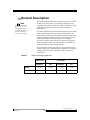
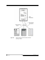
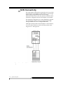
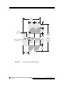
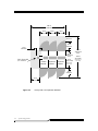
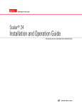
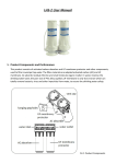
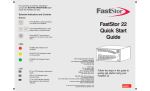
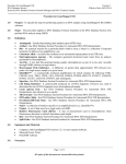
Scalar 1000 Library Planning Guide Copyright Notice © 2002–2004 ADIC The information contained in this document is subject to change without notice. This document contains proprietary information which is protected by copyright. All rights are reserved. No part of this document may be photocopied, reproduced, or translated to another language without prior written consent of ADIC. ADIC shall not be liable for errors contained herein or for incidental or consequential damages (including lost profits) in connection with the furnishing, performance or use of this material whether based on warranty, contract, or other legal theory. All trademarks are the property of their respective owners. Copyright Notice (Europe) © 2002–2004 ADIC Europe™ All rights reserved. No part of this document may be copied or reproduced in any form or by any means, without prior written permission of ADIC Europe, ZAC des Basses Auges, 1,rue Alfred de Vigny, 78112 - Fourqueux, France. ADIC Europe assumes no responsibility for any errors that may appear in this document, and retains the right to make changes to these specifications and descriptions at any time, without notice. This publication may describe designs for which patents are pending, or have been granted. By publishing this information, ADIC Europe conveys no license under any patent or any other right. ADIC Europe makes no representation or warranty with respect to the contents of this document and specifically disclaims any implied warranties of merchantability or fitness for any particular purpose. Further, ADIC Europe reserves the right to revise or change this publication without obligation on the part of ADIC Europe to notify any person or organization of such revision of change. Every effort has been made to acknowledge trademarks and their owners. Trademarked names are used solely for identification or exemplary purposes, any omission is unintentional. ADIC is a registered trademark and ADIC Europe is a trademark of Advanced Digital Information Corporation. ADIC USA Tel.: +1-303-705-3900 Fax: +1-303-792-2465 ATAC: 1-800-827-3822 www.adic.com ADIC Europe ZAC des Basses Auges 1, rue Alfred de Vigny 78112 Fourqueux, France Tel.: +33.1.3087.5300 Fax: +33.1.3087.5301 Document number: 6-01150-01 Rev A Published: 22 June 2004 ADIC Germany Beteiligungs GmbH, KG Eschenstraße 3 D-89558 Böhmenkirch, Germany Tel: +00.800.9999.3822 Printed in the USA ADIC CORPORATE • 11431 WILLOWS ROAD, NE • REDMOND, WASHINGTON, USA • 1-800-336-1233 ADIC • 8560 UPLAND DRIVE• ENGLEWOOD, COLORADO, USA • 1-800-827-3822 ADIC • 10 BROWN ROAD • ITHACA, NEW YORK, USA • 1-607-241-4800 Contents 1 Introduction Overview . . . . . . . . . . . . . . . . . . . . . . . . . . . . . . . . . . . . . . . . . . . . . . . . . . . . . . . . . . . . . . . 1-3 Intended Audience . . . . . . . . . . . . . . . . . . . . . . . . . . . . . . . . . . . . . . . . . . . . . . . . . . . . . . . 1-3 Organization . . . . . . . . . . . . . . . . . . . . . . . . . . . . . . . . . . . . . . . . . . . . . . . . . . . . . . . . . . . . 1-3 Associated Documents . . . . . . . . . . . . . . . . . . . . . . . . . . . . . . . . . . . . . . . . . . . . . . . . . . . . 1-4 ADIC Technical Assistance Center . . . . . . . . . . . . . . . . . . . . . . . . . . . . . . . . . . . . . . . . . . 1-4 2 System Description General Description . . . . . . . . . . . . . . . . . . . . . . . . . . . . . . . . . . . . . . . . . . . . . . . . . . . . . . 2-3 Modules . . . . . . . . . . . . . . . . . . . . . . . . . . . . . . . . . . . . . . . . . . . . . . . . . . . . . . . . . . . . . . . . 2-4 Control Module (CM) . . . . . . . . . . . . . . . . . . . . . . . . . . . . . . . . . . . . . . . . . . . . . . . . . 2-5 Expansion Module (EM) . . . . . . . . . . . . . . . . . . . . . . . . . . . . . . . . . . . . . . . . . . . . . . . 2-5 Internal Components . . . . . . . . . . . . . . . . . . . . . . . . . . . . . . . . . . . . . . . . . . . . . . . . . . . . . 2-6 Tape Drives . . . . . . . . . . . . . . . . . . . . . . . . . . . . . . . . . . . . . . . . . . . . . . . . . . . . . . . . . . 2-6 Cartridge Accessor . . . . . . . . . . . . . . . . . . . . . . . . . . . . . . . . . . . . . . . . . . . . . . . . . . . . 2-6 Tape Cartridges . . . . . . . . . . . . . . . . . . . . . . . . . . . . . . . . . . . . . . . . . . . . . . . . . . . . . . 2-7 Insert/Eject Station . . . . . . . . . . . . . . . . . . . . . . . . . . . . . . . . . . . . . . . . . . . . . . . . . . . 2-7 Connectivity . . . . . . . . . . . . . . . . . . . . . . . . . . . . . . . . . . . . . . . . . . . . . . . . . . . . . . . . . . . . . 2-8 SAN Connectivity . . . . . . . . . . . . . . . . . . . . . . . . . . . . . . . . . . . . . . . . . . . . . . . . . . . . 2-8 SCSI Connectivity . . . . . . . . . . . . . . . . . . . . . . . . . . . . . . . . . . . . . . . . . . . . . . . . . . . 2-10 Scalar DLC Option . . . . . . . . . . . . . . . . . . . . . . . . . . . . . . . . . . . . . . . . . . . . . . . . . . . . . . 2-11 Remote Management Unit . . . . . . . . . . . . . . . . . . . . . . . . . . . . . . . . . . . . . . . . . . . . . . . . 2-12 3 System Configurations Overview . . . . . . . . . . . . . . . . . . . . . . . . . . . . . . . . . . . . . . . . . . . . . . . . . . . . . . . . . . . . . . . 3-3 Configurations . . . . . . . . . . . . . . . . . . . . . . . . . . . . . . . . . . . . . . . . . . . . . . . . . . . . . . . . . . . 3-4 4 System Specifications Overview . . . . . . . . . . . . . . . . . . . . . . . . . . . . . . . . . . . . . . . . . . . . . . . . . . . . . . . . . . . . . . . 4-3 Performance Specifications . . . . . . . . . . . . . . . . . . . . . . . . . . . . . . . . . . . . . . . . . . . . . . . . 4-3 Environmental Specifications . . . . . . . . . . . . . . . . . . . . . . . . . . . . . . . . . . . . . . . . . . . . . . 4-3 Electrical Specifications . . . . . . . . . . . . . . . . . . . . . . . . . . . . . . . . . . . . . . . . . . . . . . . . . . . 4-4 Physical Specifications . . . . . . . . . . . . . . . . . . . . . . . . . . . . . . . . . . . . . . . . . . . . . . . . . . . . 4-5 Foot Pad Positions . . . . . . . . . . . . . . . . . . . . . . . . . . . . . . . . . . . . . . . . . . . . . . . . . . . . . . . . 4-6 Barcode Requirements . . . . . . . . . . . . . . . . . . . . . . . . . . . . . . . . . . . . . . . . . . . . . . . . . . . . 4-7 iv Contents 6-01150-01 Rev A 5 Site Preparation Overview . . . . . . . . . . . . . . . . . . . . . . . . . . . . . . . . . . . . . . . . . . . . . . . . . . . . . . . . . . . . . . . 5-3 Packaging Dimensions . . . . . . . . . . . . . . . . . . . . . . . . . . . . . . . . . . . . . . . . . . . . . . . . . . . . 5-3 General Information . . . . . . . . . . . . . . . . . . . . . . . . . . . . . . . . . . . . . . . . . . . . . . . . . . . . . . 5-4 Physical Environment . . . . . . . . . . . . . . . . . . . . . . . . . . . . . . . . . . . . . . . . . . . . . . . . . . . . . 5-5 Access Conditions . . . . . . . . . . . . . . . . . . . . . . . . . . . . . . . . . . . . . . . . . . . . . . . . . . . . 5-5 Additional Comments . . . . . . . . . . . . . . . . . . . . . . . . . . . . . . . . . . . . . . . . . . . . . . . . . 5-9 Index 22 June 2004 Contents v vi Contents 6-01150-01 Rev A Figures Figure 2-1 Control Module and Expansion Module . . . . . . . . . . . . . . . . . . . . . . . 2-4 Figure 2-2 Storage Networking Fibre Channel Attachment (Through an SNC) . . . . . . . . . . . . . . . . . . . . . . . . . . . . . . . . . . . . . . . . . . 2-9 Figure 2-3 Direct SCSI Attachment . . . . . . . . . . . . . . . . . . . . . . . . . . . . . . . . . . . . 2-10 Figure 2-4 Network Attachment . . . . . . . . . . . . . . . . . . . . . . . . . . . . . . . . . . . . . . 2-12 Figure 3-1 Basic Library with No Expansion Modules . . . . . . . . . . . . . . . . . . . . . 3-4 Figure 3-2 Library with One Expansion Module. . . . . . . . . . . . . . . . . . . . . . . . . . 3-5 Figure 3-3 Library with Two Expansion Modules. . . . . . . . . . . . . . . . . . . . . . . . . 3-6 Figure 3-4 Library with Three Expansion Modules . . . . . . . . . . . . . . . . . . . . . . . 3-7 Figure 4-1 Foot Pad Positions (Control Module and Expansion Module). . . . . 4-6 viii Figures 6-01150-01 Rev A Tables Table 2-1 Drives and Storage Capacities . . . . . . . . . . . . . . . . . . . . . . . . . . . . . . . 2-3 Table 3-1 Library Configurations . . . . . . . . . . . . . . . . . . . . . . . . . . . . . . . . . . . . . 3-3 Table 4-1 Performance Specifications . . . . . . . . . . . . . . . . . . . . . . . . . . . . . . . . . 4-3 Table 4-2 Environmental Specifications . . . . . . . . . . . . . . . . . . . . . . . . . . . . . . . 4-3 Table 4-3 Electrical Specifications . . . . . . . . . . . . . . . . . . . . . . . . . . . . . . . . . . . . 4-4 Table 4-4 Typical Component Power Consumption (Worst Case) . . . . . . . . . 4-4 Table 4-5 Physical Specifications . . . . . . . . . . . . . . . . . . . . . . . . . . . . . . . . . . . . . 4-5 x Tables 6-01150-01 Rev A 1 Introduction Overview . . . . . . . . . . . . . . . . . . . . . . . . . . . . . . . . . . . . . . . . . . . . . . . . . . . . . . . . . . . . . . . 1-3 Intended Audience . . . . . . . . . . . . . . . . . . . . . . . . . . . . . . . . . . . . . . . . . . . . . . . . . . . . . . . 1-3 Organization . . . . . . . . . . . . . . . . . . . . . . . . . . . . . . . . . . . . . . . . . . . . . . . . . . . . . . . . . . . . 1-3 Associated Documents . . . . . . . . . . . . . . . . . . . . . . . . . . . . . . . . . . . . . . . . . . . . . . . . . . . . 1-4 ADIC Technical Assistance Center . . . . . . . . . . . . . . . . . . . . . . . . . . . . . . . . . . . . . . . . . . 1-4 2 Introduction 6-01150-01 Rev A 1- Overview This chapter provides general information on this manual, including intended audience, organization, associated documents, and where to acquire technical assistance. The information in this chapter is organized as follows: • Intended Audience on page 1-3 • Organization on page 1-3 • Associated Documents on page 1-4 • ADIC Technical Assistance Center on page 1-4 Intended Audience This manual is for sales personnel and potential purchasers of the Scalar 10001 library. Organization This manual contains information detailing the Scalar 1000 library. The chapters include: Chapter 1 About this Guide - Describes the intended audience, organization, associated documents, and where to acquire additional assistance. Chapter 2 System Description - Describes general information, Scalar 1000 library modules, I/O status and control, and host attachments. Chapter 3 System Configurations - Describes the structure of the basic Scalar 1000 library and available optional components. Chapter 4 System Specifications - Describes the physical and electrical specifications of the Scalar 1000 components. 1. Scalar 1000 is a trademark of ADIC. Throughout the remainder of this document, we refer to Scalar 1000 library as Scalar 1000 or the library. 22 June 2004 Overview 1-3 Chapter 5 Site Preparation - Provides forms for planning space, physical, electrical, and environmental requirements. This information is required by the installation team. Associated Documents 6-00054-xx Scalar 1000 Operator Guide 6-00055-xx Scalar 1000 SCSI Reference Manual 6-01151-xx Scalar 1000 Maintenance Guide ADIC Technical Assistance Center If problems cannot be solved with the aid of this document or if recommended training is desired, contact the ADIC Technical Assistance Center (ATAC). 1-4 Introduction • In the USA: 800.827.3822 • Outside the USA, toll free: 00.800.9999.3822 • email: [email protected] 6-01150-01 Rev A 2 System Description General Description . . . . . . . . . . . . . . . . . . . . . . . . . . . . . . . . . . . . . . . . . . . . . . . . . . . . . . 2-3 Modules . . . . . . . . . . . . . . . . . . . . . . . . . . . . . . . . . . . . . . . . . . . . . . . . . . . . . . . . . . . . . . . . 2-4 Control Module (CM) . . . . . . . . . . . . . . . . . . . . . . . . . . . . . . . . . . . . . . . . . . . . . . . . . 2-5 Expansion Module (EM) . . . . . . . . . . . . . . . . . . . . . . . . . . . . . . . . . . . . . . . . . . . . . . . 2-5 Internal Components . . . . . . . . . . . . . . . . . . . . . . . . . . . . . . . . . . . . . . . . . . . . . . . . . . . . . 2-6 Tape Drives . . . . . . . . . . . . . . . . . . . . . . . . . . . . . . . . . . . . . . . . . . . . . . . . . . . . . . . . . . 2-6 Cartridge Accessor . . . . . . . . . . . . . . . . . . . . . . . . . . . . . . . . . . . . . . . . . . . . . . . . . . . . 2-6 Tape Cartridges . . . . . . . . . . . . . . . . . . . . . . . . . . . . . . . . . . . . . . . . . . . . . . . . . . . . . . 2-7 Insert/Eject Station . . . . . . . . . . . . . . . . . . . . . . . . . . . . . . . . . . . . . . . . . . . . . . . . . . . 2-7 Connectivity . . . . . . . . . . . . . . . . . . . . . . . . . . . . . . . . . . . . . . . . . . . . . . . . . . . . . . . . . . . . . 2-8 SAN Connectivity . . . . . . . . . . . . . . . . . . . . . . . . . . . . . . . . . . . . . . . . . . . . . . . . . . . . 2-8 SCSI Connectivity . . . . . . . . . . . . . . . . . . . . . . . . . . . . . . . . . . . . . . . . . . . . . . . . . . . 2-10 Scalar DLC Option . . . . . . . . . . . . . . . . . . . . . . . . . . . . . . . . . . . . . . . . . . . . . . . . . . . . . . 2-11 Remote Management Unit . . . . . . . . . . . . . . . . . . . . . . . . . . . . . . . . . . . . . . . . . . . . . . . . 2-12 2 System Description 6-01150-01 Rev A 2- General Description The Scalar 1000 automates the storage, retrieval, and control of 3590, LTO, DLT, SDLT, and AIT tape cartridges. Tape cartridges are mounted and dismounted in tape drives using application software from the host without operator intervention. Note To accommodate IBM 3590 drives, you must add an Extension frame to a Control Module or an Expansion Module to increase module depth. The Scalar 1000 is a linear storage library that can be expanded from a single media library to a mixed media library. The Scalar 1000 consists of a Control Module (CM) and up to three Expansion Modules (EMs). See Figure 2-1 on page 2-4. The CM contains library control hardware, the Cartridge Accessor, an Insert/Eject Station (I/E Station), an Operator Panel, cartridge storage cells, and tape drives. The EM can contain tape drives and cartridge storage. The Scalar 1000 can be configured for approximately 118 to 1182 cartridges (the cartridge capacity depends on the library configuration and features installed), and 1 to 48 drives. See Table 2-1. Table 2-1 Drives and Storage Capacities High Profile Drives Cartridges 22 June 2004 Low Profile 3590/DLT LTO DLT/SDLT AIT 1 - 16 1 - 48 1 - 48 1 - 48 118 - 788 140 - 938 118 - 788 237 - 1182 General Description 2-3 Modules The Scalar 1000 Library has the following modules: • Control Module (CM) on page 2-5 • Expansion Module (EM) on page 2-5 Door Lock, Handle, and Key Operator Panel Insert/Eject Station Expansion Module Control Module Figure 2-1 2-4 System Description Control Module and Expansion Module 6-01150-01 Rev A Control Module (CM) The CM is a single module, standalone Scalar 1000 library. It contains an LCD Operator Panel, AC and DC power supplies, robot control electronics, and host interfaces. It can be attached to an EM to create an expanded Scalar 1000 library. See Figure 2-1 on page 2-4. The tape and drive bay capacity varies in the CM. Each drive bay accommodates: • One or two High Profile tape drives • One to six Low Profile tape drives • One to 12 Low Profile 8 mm (AIT) tape drives Expansion Module (EM) The EM extends the length of the aisle and adds drives and cartridges to the library. The Scalar 1000 maximum configuration includes three EMs. These modules extend the X-rails (top and bottom) which allow the Accessor to travel the length of the library. See Figure 2-1 on page 2-4. 22 June 2004 Modules 2-5 Internal Components The Scalar 1000 consists of the following internal components: • Tape Drives • Cartridge Storage • Cartridge Accessor • Tape Cartridges • Insert/Eject Station Tape Drives The Scalar 1000 supports the following tape drives: • 3490E • NCTP • 3590 • DLT (high profile and low profile) • SDLT • AIT-1 • AIT-2 • AIT-3 • LTO-1 • LTO-2 Cartridge Accessor The Cartridge Accessor identifies and moves cartridges between the storage cells, tape drives, and the I/E Station. The Cartridge Accessor has: 2-6 System Description • A Gripper Assembly for getting and putting cartridges in storage cells, tape drives or the I/E Station. • A Barcode Scanner for reading the external barcode labels on the cartridges. The Barcode Scanner is used during the inventory process to locate and categorize all cartridges installed in the library. It is also used during the teaching process in which it reads the fiducial labels to identify the types of storage arrays and tape drives installed in the Library. (Fiducial labels are barcode labels located on tape drives and storage arrays. Each label has a different value to identify the various types of storage arrays or tape drives that may be installed in the Library. Refer to the Scalar 1000 Operator Guide for a list of all fiducial labels.) 6-01150-01 Rev A • An X-Axis drive for moving the Cartridge Accessor the length of the rails in the CM and the EMs. • A Y-Axis drive for moving the Gripper Assembly vertically in the CM and the EMs. Tape Cartridges The Scalar 1000 automates the retrieval, storage, and control of 3590, DLT, SDLT, LTO, and AIT cartridges. Note Duplicate barcode labels (even with different media identifiers) are NOT supported. Two characters are used to identify the cartridge type. For SDLT and LTO cartridges, the media identifier is embedded at the end of the barcode label. Any code 39 labels are supported. Refer to the Scalar 1000 Operator Guide for more information on label types supported by the Scalar 1000. Insert/Eject Station The I/E Station allows for the insertion and ejection of cartridges without interrupting the normal operation of the library. The I/E Station uses two different cartridge magazines. One magazine has a capacity of six half-inch cartridges (3590/ DLT/SDLT/LTO), the other magazine has a capacity of nine 8 mm (AIT) cartridges. A maximum of two magazines of any type can be present in the I/E Station at any time. If you have two different magazines in an I/E Station, such as one halfinch and one 8 mm magazine, the library requires Scalar DLC. For more information on Scalar DLC, refer to Scalar DLC Option on page 2-11 or contact an ADIC representative. The coordinate for the rows in the old style I/E Station is always contiguous (1 to 12 for half-inch and 1 to 18 for 8 mm). Since two magazines of different cartridge types can be present in the I/E station at any time, the first cell of the bottom magazine of the new style I/E station always starts with Row 10. 22 June 2004 Internal Components 2-7 Connectivity The Scalar 1000 offers several different connectivity options, allowing the library to support a wide range of backup topologies and applications. Flexible library connectivity delivers active support for loop and switched fabric Fibre Channel protocols, along with SCSI. SAN Connectivity The Scalar 1000 can be connected to a Fibre Channel Storage Area Network (SAN) via the Storage Networking Controller (SNC). The SNC provides four parallel SCSI bus connections, one ethernet, and two Fibre Channel connections. The SNC allows native SCSI devices (for example: robot controller and tape drives) to be seen by any hosts that are attached to the SAN. The library controller and the tape drives access the SAN via the SNCs that can be installed in a Scalar 1000 CM or EM. See Figure 2-2 on page 2-9. 2-8 System Description 6-01150-01 Rev A Figure 2-2 22 June 2004 Storage Networking Fibre Channel Attachment (Through an SNC) Connectivity 2-9 SCSI Connectivity The Scalar 1000 can be directly connected to one or two SCSI buses. Because each SCSI bus is independent, it can be Single Ended, High Voltage Differential, or Low Voltage Differential. Both ends of each bus must be terminated and a terminator is shipped with each SCSI adapter card ordered. The minimum configuration of a Scalar 1000 library requires one SCSI adapter and the SCSI type (Single Ended, High Voltage Differential or Low Voltage Differential). Although the Scalar 1000 can be attached to a wide SCSI bus, it is not a wide SCSI device and its SCSI ID must be in the range of 0 to 7. See Figure 2-3. Figure 2-3 2-10 System Description Direct SCSI Attachment 6-01150-01 Rev A Scalar DLC Option The Scalar 1000, through its optional Scalar Distributed Library Control (Scalar DLC) interface, provides the industry’s most advanced combination of management and diagnostics. The Scalar DLC software serves as a centralized library management tool that simplifies and automates the tracking and management of all system resources for optimal performance and maximum availability. The Scalar DLC attaches to the library SCSI bus. The host continues to directly attach to the drives through a SCSI or a Fibre Channel Interface. For more information on Scalar DLC, including detailed information on the supported interfaces, refer to ADIC Scalar DLC documentation. See Figure 2-4 on page 2-12 for more information. 22 June 2004 Scalar DLC Option 2-11 Figure 2-4 Network Attachment Remote Management Unit The factory-installed Remote Management Unit (RMU) in each system uses a standard web browser for remote library access. The supported browsers are: • Microsoft Internet Explorer version 4.0 and above • Netscape Navigator version 4.7 and above With an RMU, you are able to do the following: 2-12 System Description • Update RMU firmware • Access the library status • Make configuration changes 6-01150-01 Rev A • Access the library Operator Panel • Access Scalar 1000 documentation • Retrieve library command and event logs The RMU supports Simple Network Management Protocol (SNMP) version 2.0 and acts as an SNMP-server. The RMU acquires Tape Alert 3.0 compatible information from the library over the serial interface port and sends that information to a SNMP manager. The RMU also detects a power loss and generates a SNMP trap for notification. For additional information, refer to the Scalar 1000 Operator Guide. 22 June 2004 Remote Management Unit 2-13 2-14 System Description 6-01150-01 Rev A 3 System Configurations Overview . . . . . . . . . . . . . . . . . . . . . . . . . . . . . . . . . . . . . . . . . . . . . . . . . . . . . . . . . . . . . . . 3-3 Configurations . . . . . . . . . . . . . . . . . . . . . . . . . . . . . . . . . . . . . . . . . . . . . . . . . . . . . . . . . . . 3-4 2 System Configurations 6-01150-01 Rev A 3- Overview This chapter describes the Scalar 1000 library component configurations. The Scalar 1000 can consist of one to four modules (a Control Module and up to three Expansion Modules). See Table 3-1 for module, tape drive, and tape cartridge configuration information. Note Service requires 48 in. (1219 mm) access. Table 3-1 Library Configurations LTO/DLT/SDLT Drives LTO/DLT/SDLT Control Module Control Module and 1 Expansion Module Control Module and 2 Expansion Modules Control Module and 3 Expansion Modules 22 June 2004 AIT 3590 Cartridges LTO Drives Cartridges Drives Cartridges 2–12 237 1–2 158 DLT/SDLT 1–6 188 158 7–12 140 118 1–6 438 368 2–12 552 1–2 368 7–12 390 328 14–24 492 3–4 328 13–18 342 288 5–6 288 19–24 294 248 7–8 248 1–6 688 578 2–12 867 1–2 578 538 7–12 640 538 14–24 807 3–4 13–18 592 498 26–36 747 5–6 498 19–24 544 458 7–8 458 25–30 496 418 9–10 418 31–36 448 378 11–12 378 1–6 938 788 2–12 1182 1–2 788 7–12 890 748 14–24 1122 3–4 748 13–18 842 708 26–36 1062 5–6 708 19–24 794 688 38–48 1002 7–8 668 25–30 746 628 9–10 628 31–36 698 588 11–12 588 37–42 650 548 13–14 548 43–48 602 508 15–16 508 Overview 3-3 Configurations This section contains figures that show the four possible Scalar 1000 component configurations. • Basic Library with No Expansion Modules, Figure 3-1 • Library with One Expansion Module, Figure 3-2 on page 3-5 • Library with Two Expansion Modules, Figure 3-3 on page 3-6 • Library with Three Expansion Modules, Figure 3-4 on page 3-7 60 in. 1524 mm 30 in. 762 mm Service 18 in. Access 48 in. 457 mm 1219 mm 30 in. 762 mm 12 in. 305 mm 138 in. 3505 mm 60 in. 1524 mm (3590) Fully Extended I/E Station Control Module 47 in. 1193.8 mm (3590) 125 in. 3175 mm (SDLT/DLT, LTO, AIT) (SDLT/DLT, LTO, AIT) 30 in. 762 mm 30 in. 762 mm Figure 3-1 3-4 System Configurations Basic Library with No Expansion Modules 6-01150-01 Rev A 90 in. 2280 mm 30 in. 30 in. 762 mm 762 mm 18 in. 457 mm 30 in. 762 mm 12 in. 305 mm 60 in. 1524 mm (3590) Fully Extended I/E Station Control Module Expansion Module 47 in. 1193.8 mm (SDLT/DLT, LTO, AIT) 138 in. 3505 mm (3590) 125 in. 3175 mm (SDLT/DLT, LTO, AIT) 30 in. 762 mm 30 in. 762 mm Figure 3-2 22 June 2004 Library with One Expansion Module Configurations 3-5 120 in. 3048 mm 30 in. 762 mm 30 in. 762 mm 30 in. 762 mm 18 in. 457 mm 30 in. 762 mm 12 in. 305 mm 138 in. 3505 mm 60 in. 1524 mm (3590) Fully Extended I/E Station Control Module Expansion Module Expansion Module 47 in. 1193.8 mm (3590) 125 in. 3175 mm (SDLT/DLT, LTO, AIT) (SDLT/DLT, LTO, AIT) 30 in. 762 mm 30 in. 762 mm Figure 3-3 3-6 System Configurations Library with Two Expansion Modules 6-01150-01 Rev A 150 in. 3810 mm 30 in. 762 mm 30 in. 762 mm 30 in. 762 mm 30 in. 762 mm 18 in. 457 mm 30 in. 762 mm 12 in. 305 mm 60 in. 1524 mm (3590) Fully Extended I/E Station Control Module Expansion Module Expansion Module Expansion Module 47 in. 1193.8 mm (SDLT/DLT, LTO, AIT) 138 in. 3505 mm (3590) 125 in. 3175 mm (SDLT/DLT, LTO, AIT) 30 in. 762 mm 30 in. 762 mm Figure 3-4 22 June 2004 Library with Three Expansion Modules Configurations 3-7 3-8 System Configurations 6-01150-01 Rev A 4 System Specifications Overview . . . . . . . . . . . . . . . . . . . . . . . . . . . . . . . . . . . . . . . . . . . . . . . . . . . . . . . . . . . . . . . 4-3 Performance Specifications . . . . . . . . . . . . . . . . . . . . . . . . . . . . . . . . . . . . . . . . . . . . . . . . 4-3 Environmental Specifications . . . . . . . . . . . . . . . . . . . . . . . . . . . . . . . . . . . . . . . . . . . . . . 4-3 Electrical Specifications . . . . . . . . . . . . . . . . . . . . . . . . . . . . . . . . . . . . . . . . . . . . . . . . . . . 4-4 Physical Specifications . . . . . . . . . . . . . . . . . . . . . . . . . . . . . . . . . . . . . . . . . . . . . . . . . . . . 4-5 Foot Pad Positions . . . . . . . . . . . . . . . . . . . . . . . . . . . . . . . . . . . . . . . . . . . . . . . . . . . . . . . . 4-6 Barcode Requirements . . . . . . . . . . . . . . . . . . . . . . . . . . . . . . . . . . . . . . . . . . . . . . . . . . . . 4-7 2 System Specifications 6-01150-01 Rev A 4- Overview This chapter contains performance, environmental, electrical, and physical specification information for the Scalar 1000 library. The information is organized as follows: • Performance Specifications on page 4-3 • Environmental Specifications on page 4-3 • Electrical Specifications on page 4-4 • Physical Specifications on page 4-5 • Foot Pad Positions on page 4-6 • Barcode Requirements on page 4-7 Performance Specifications The Scalar 1000 has peak actions per hour of 350 exchanges and peak time to mount media of 6 seconds. Table 4-1 Performance Specifications Avg Actions per Hour Peak Actions per Hour Avg Time to Mount Media Max Time to Mount Media 290 350 5 Seconds 6 Seconds Environmental Specifications Table 4-2 lists the key environmental information for the Scalar 1000 library. Specifications do not include drives. Table 4-2 Environmental Specifications Temperature Humidity Operating: Non-condensing 60° - 90° F (16° - 32° C) Operating: 15 - 75% Altitude No Limit Maximum BTU/Heat Dissipation 0.44 kwh 1502 BTU Recommended: Recommended: 45 - 65% 70° - 75° F (21° - 24° C) 22 June 2004 Overview 4-3 Electrical Specifications The electrical specifications for the Control Module (CM) and Expansion Module (EM) are shown in Table 4-3. Table 4-3 Electrical Specifications Module Voltage a (Single Phase) kVA United States Power Connector International Power Connector CM/EM 115 - 230 1.6 L5 - 20 Plug is customer supplied a. Connect an 18 gauge stranded copper wire from the CM to earth ground. The typical power consumption for a full-height/half-height drive and the SNC 5100 is shown in Table 4-4. Table 4-4 Typical Component Power Consumption (Worst Case) Component Watts BTU Read/Write 71.5 244 Idle 53.0 180 Half-Height Drive (Two in sled AIT) Read/Write 53.8 263 Idle 24.6 120 SNC 5100 Read/Write 33 113 Full-Height Drive Status The EMs only need power if there are drive bays installed. 4-4 System Specifications 6-01150-01 Rev A Physical Specifications The physical specifications for the library modules are shown in Table 4-5. The floor must support point loads exerted by the leveling pads of up to 86.42 lb./in2. In addition to being dust-free, physically, chemically, and acoustically appropriate, the flooring must meet the insulation resistance specifications. The insulation resistance between the floor surface and earth ground must be 1x10⁵ to 1x10⁸ ohms to prevent system failure or electrical shock. Sufficient resistance is achieved by using antistatic, nonconducting floor tile with a resistance of 1x10⁶ to 1x10⁹ ohms. If necessary, provide an appropriate connection to the metal portion of the ground plane. The Scalar 1000 has four point loads on the CM and EM. Table 4-5 Height Physical Specifications Width Depth Maximum Weight Distributed Load Point Load 85 lb./ft2 414 Kg/m2 86.42 lb./in.2 421.88 Kg/m2 Control Module 72 in. 1828.8 mm 29.6 in. 751.8 mm 47 in. 1193.8 mm (SDLT/DLT/ LTO/AIT) 1052 lb. 477 Kg 60 in. 1524 mm (3590) Expansion Module 72 in. 1828.8 mm 29.6 in. 751.8 mm 47 in. 1193.8 mm (SDLT/DLT/ LTO/AIT) 817 lb. 371 Kg 66.00 lb./ft2 67.11 lb./in.2 322.2 Kg/m2 327 Kg/m2 60 in. 1524 mm (3590) 22 June 2004 Physical Specifications 4-5 Foot Pad Positions The Scalar 1000 foot pad positions are shown in Figure 4-1. The foot pad positions are the same for the CM and EM. 29.65 in. (753.2 mm) 46.71 in. (1186.4 mm) 2X 41.09 in. (1043.8 mm) 4X 2.00 in. (50.8 mm) 2X 2.81 in. (71.3 mm) 2X 1.84 in. (46.7 mm) 25.98 in. (659.8 mm) Figure 4-1 4-6 System Specifications Foot Pad Positions (Control Module and Expansion Module) 6-01150-01 Rev A Barcode Requirements For customers who want to print barcode labels, the labels must meet the ANSI MH10.8M-1983 standard and other additional requirements. The following list outlines the ANSI MH10.8M-1983 standard and additional requirements: • ANSI MH10.8M-1983 Standard • • • • • • Additional requirements • • • • • 22 June 2004 Number of digits: • 5 - 16 in extended mode • 6 (7 or 8 including media characters) in default and mixed media modes • Background reflection: at least 25 percent Print contrast: at least 75 percent Ratio: at least 2.2 Module: 250 mm Print tolerance: ± 57 mm Length of the rest zones: 5.00 mm minimum No black marks can be present in the intermediate spaces or rest zones No white areas may be present on the bars A nine digit bar code must not match the serial numbers of any frames of the unit, otherwise it will be ignored Each label should be applied in the upper right corner of the tape cartridge recess (when oriented vertically) Barcode Requirements 4-7 4-8 System Specifications 6-01150-01 Rev A 5 Site Preparation Overview . . . . . . . . . . . . . . . . . . . . . . . . . . . . . . . . . . . . . . . . . . . . . . . . . . . . . . . . . . . . . . . 5-3 Packaging Dimensions . . . . . . . . . . . . . . . . . . . . . . . . . . . . . . . . . . . . . . . . . . . . . . . . . . . . 5-3 General Information . . . . . . . . . . . . . . . . . . . . . . . . . . . . . . . . . . . . . . . . . . . . . . . . . . . . . . 5-4 Physical Environment . . . . . . . . . . . . . . . . . . . . . . . . . . . . . . . . . . . . . . . . . . . . . . . . . . . . . 5-5 Access Conditions . . . . . . . . . . . . . . . . . . . . . . . . . . . . . . . . . . . . . . . . . . . . . . . . . . . . 5-5 Additional Comments . . . . . . . . . . . . . . . . . . . . . . . . . . . . . . . . . . . . . . . . . . . . . . . . . 5-9 2 Site Preparation 6-01150-01 Rev A 5- Overview This section solicits pertinent information about the delivery site. Record all requested general information. Packaging Dimensions The Scalar 1000 module packaging sizes are as follows: • Control Module (CM) packing size: 65 in. L (1651 mm) x 35 in. W (889 mm) x 78 in. H (1981 mm) and mounted on 150 lb. palettes. • Expansion Module (EM) packing size: 65 in. L (1651 mm) x 35 in. W (889 mm) x 78 in. H (1981 mm) and mounted on 150 lb. palettes. 22 June 2004 Overview 5-3 General Information Note Customer Name: Place any additional information in Additional Comments on page 5-9. Mailing Address: Shipping Address: Sales Contact: Telephone: ADIC Sales Rep: ADIC Account Mgr: Installation Contact: Telephone: Target Installation Date: 5-4 Site Preparation 6-01150-01 Rev A Target Operational Date: Physical Environment Place any additional information in Additional Comments on page 5-9. Room Dimension: Ceiling Projection Floor Type Floor Load Capacity Fire Protection Access Conditions Access to Scalar 1000 library room (elevator, stairs, door widths, etc.): 22 June 2004 Physical Environment 5-5 Dimensions and Location of Smallest Door or Opening: Loading Dock Specifications (dock height, type of ramps, weather protection, etc.): 5-6 Site Preparation 6-01150-01 Rev A Semitrailer Accessibility (Y or N): ________ Preferred/Required Local Carrier Company: Where Can Trailer Be Left for Staging? Availability of Material Handling Equipment: Location for uncrating: Preferred Time of Day for Unloading and Moving Materials: 22 June 2004 Physical Environment 5-7 Off Hours/Weekends Accessibility for Installation Team: Procedure for Obtaining Building Passes: Procedure for Scheduling the Elevator, Loading Dock, etc.: Waste Disposal Considerations: Bargaining Unit Considerations: 5-8 Site Preparation 6-01150-01 Rev A Other Considerations: Additional Comments Record any additional information from other pages. For reference purposes, note the page number with the information. Add and number additional sheets as necessary. 22 June 2004 Physical Environment 5-9 5-10 Site Preparation 6-01150-01 Rev A Index -AAccess Conditions . . . . . . . . . . . . . . . . . . . . . . . 5-5 Additional Comments . . . . . . . . . . . . . . . . . . . . 5-9 Assistance with Problems . . . . . . . . . . . . . . . . . 1-4 Associated Documents . . . . . . . . . . . . . . . . . . . 1-4 ATAC . . . . . . . . . . . . . . . . . . . . . . . . . . . . . . . . . . 1-4 -BBarcode Requirement . . . . . . . . . . . . . . . . . . . . 4-7 Insert/Eject Station . . . . . . . . . . . . . . . . . . . . . . .2-7 Intended Audience . . . . . . . . . . . . . . . . . . . . . . .1-3 -OOperator Panel . . . . . . . . . . . . . . . . . . . . . . . . . .2-3 -PPerformance Specifications . . . . . . . . . . . . . . . .4-3 Physical Environment . . . . . . . . . . . . . . . . . . . .5-5 Physical Specifications . . . . . . . . . . . . . . . . . . . .4-5 -CCartridge Accessor . . . . . . . . . . . . . . . . . . . 2-3, 2-6 Chapter Organization . . . . . . . . . . . . . . . . . . . . 1-3 Control Module . . . . . . . . . . . . . . . . . . . . . . . . . 2-3 -EElectrical Specifications . . . . . . . . . . . . . . . . . . . 4-4 Environmental Specifications . . . . . . . . . . . . . . 4-3 Expansion Module . . . . . . . . . . . . . . . . . . . . . . . 2-3 -FFoot Pad Positions Control Module . . . . . . . . . . . . . . . . . . . . . . 4-6 Expansion Module . . . . . . . . . . . . . . . . . . . 4-6 -GGeneral Description . . . . . . . . . . . . . . . . . . . . . . 2-3 General Information . . . . . . . . . . . . . . . . . . . . . 5-4 -IInsert/Eject Magazines . . . . . . . . . . . . . . . . . . . 2-3 -RRemote Management Unit . . . . . . . . . . . . . . .2-13 -SSAN Connectivity . . . . . . . . . . . . . . . . . . . . . . . .2-8 Scalar DLC . . . . . . . . . . . . . . . . . . . . . . . . . . . . .2-11 SCSI Connectivity . . . . . . . . . . . . . . . . . . . . . . .2-10 SNMP . . . . . . . . . . . . . . . . . . . . . . . . . . . . . . . . .2-13 Specifications Electrical Specifications . . . . . . . . . . . . . . .4-4 Environmental Specifications . . . . . . . . . .4-3 Performance Specifications . . . . . . . . . . . .4-3 Physical Specifications . . . . . . . . . . . . . . . .4-5 Storage Cells . . . . . . . . . . . . . . . . . . . . . . . . . . . .2-3 -TTape Cartridges . . . . . . . . . . . . . . . . . . . . . . . . . .2-7 Technical Assistance . . . . . . . . . . . . . . . . . . . . . .1-4 in-2 Index 6-01150-01 Rev A