1
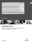
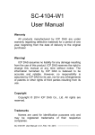
DX3000 and DX5000
Quick Start Guide
TABLE OF CONTENTS
Introduction .......................................1
Notational Conventions .................1
Choosing a Location ..........................2
Rack Space Requirements...............2
Environmental Conditions .............2
Introduction
0
This quick start guides provides basic installation and configuration instructions for
both the DX3000 and DX5000 systems (see figure 1). For more information, see
the Quantum DX3000 and DX5000 User’s Guide on the documentation CD
provided with your DX3000 or DX5000 system.
Preparing for the Installation ...........2
Providing Necessary Tools ..............2
Taking ESD Precautions ..................2
Unpacking the DX3000/DX5000.........2
Installing the DX3000/DX5000 System3
Locating the Mounting Position ....3
Installing the DX3000/DX5000
Chassis .............................................4
Cabling the DX3000/DX5000..............7
Cabling a DX3000 System...............7
Notational Conventions
0
This instruction uses the following conventions:
NOTE: Notes emphasize important information related to the main topic.
CAUTION:
Cautions indicate potential hazards to equipment and are included
to prevent damage to equipment.
Cabling a DX5000 System...............8
Initial Configuration ..........................8
WARNING: Warnings indicate potential hazards to personal safety and are
included to prevent injury.
Figure 1 PX3000 and DX5000
DX3000 and DX5000 Quick Start Guide
Choosing a Location
0
The DX3000/DX5000 must be installed in a restricted access
location per specification EN69050-1. This system must only
be installed by qualified IT service personnel. This is required
to prevent untrained personnel from allowing body parts or
electrically conductive items to penetrate into the interior of
the system when replacing or installing drives, fans, and
power supplies.
When choosing an installation site for the DX3000/DX5000
system, consider the following requirements:
•
Rack Space Requirements
•
Environmental Conditions
Rack Space Requirements
Preparing for the Installation
0
Before you begin the installation procedure in this section,
make the following preparations as described in this
section:
•
Providing Necessary Tools
•
Taking ESD Precautions
Providing Necessary Tools
0
Provide the following tools for unpacking and installing the
DX3000 and DX5000 systems:
0
Table 1 contains the rack requirements for both the DX3000
and DX5000.
•
#1 PHILLIPS® screwdriver
•
#2 PHILLIPS screwdriver
•
#1 Flat head screwdriver
•
Antistatic wrist strap included in accessory kit
Taking ESD Precautions
0
Table 1 Rack Requirements
DX3000
DX5000
Depth
27 in (68.6 cm)
25.4 in (64.5 cm)
Width
19 in (48.3 cm)
19 in (48.3 cm)
Height
3.5 in (8.9 cm),
2U
8.75 (22.2 cm), 5U
Weight
50 lbs (22.68 kg)
122 (55.34 kg)
Air
Clearance
Open 4 in (10.2 cm) behind unit for proper
air flow
Environmental Conditions
0
The installation site must have the following environmental
conditions:
•
Humidity: 20%-80% non-condensing
•
Temperature: 10°C-35°C (50°F-95°F)
•
Altitude: 0 to 10,000 feet (0 to 3048 meters)
These environmental conditions apply when the DX-Series
system is in operation.
NOTE: For additional specifications, refer to the
Quantum DX3000 and DX5000 User’s Guide (PN
81-81493)
Some components within the DX3000 and DX5000 systems
contain static-sensitive parts. To avoid damaging these parts
while performing installation procedures, always observe
the following precautions:
•
Keep the DX3000/DX5000 system turned off during all
installation procedures.
•
Use an antistatic wrist strap (included in the accessory
kit).
•
Keep static-sensitive parts in their original shipping
containers until ready for installation.
•
Do not place static-sensitive parts on a metal surface.
Place them inside their protective shipping bag or on an
antistatic mat.
•
Avoid touching connectors and other components.
NOTE: Dry climates and cold-weather heating
environments have lower relative humidity and
are more likely to produce static electricity.
Unpacking the DX3000/DX5000
0
This section explains how to unpack both the DX3000 and
DX5000 system components and move them to their final
installation location.
By following these instructions, you help ensure that the
system will continue to be safeguarded after it arrives at the
installation site.
2
DX3000 and DX5000 Quick Start Guide
Unpack and remove the following components from the
packing materials (see figure 2 and figure 3):
•
DX3000 or DX5000 chassis
•
Hard drive sleds
•
Accessory kit
Figure 3 Unpacking the DX5000
Accessory kit
Foam
WARNING: The DX3000 weighs 38 lbs (17.24 kg) and
the DX5000 weights 85 lbs (38.56 kg)
without hard drives. Two people are required
to lift either unit.
Antistatic
bag
Foam
Hard drive
sleds
Figure 2 Unpacking the DX3000
Lift point
Foam
DX5000
chassis
Foam
DX3000 chassis
Lift point
Foam
Foam
Rail kit
Antistatic
bag
Cables
Quick start
Foam
Hard drive
sleds
Installing the DX3000/DX5000
System
0
Installing the DX3000/5000 in a rack consists of the
following steps:
•
Locating the Mounting Position
•
Installing the DX3000/DX5000 Chassis
Locating the Mounting
Position
0
Both the DX3000 and DX5000 systems are designed to fit in
a standard 19 inch wide rack. It is important to the chassis
installation to locate the hole pattern in the rack rails (see
figure 4).
3
DX3000 and DX5000 Quick Start Guide
Figure 4 Rail Hole Pattern
Installing the DX3000/
DX5000 Chassis
0
7U of rack space
1 Assemble the DX3000/DX5000 support brackets
figure 5:
5U
For the DX5000 - The DX5000 rails are preset for
easy installation. Loosen the two nuts securing the
back portion of the rail so the rail can adjust to the
depth of the rack.
•
For the DX3000 - The DX3000 rails are preset for
28 in (71.1cm). Loosen the nuts to adjust the rails
to the depth of the rack.
1 DX5000 System (5U)
1U = 1.75 in
(44.45mm)
1 DX3000 System (2U)
2U
•
1U = 1.75 in
(44.45mm)
The marks above (X)
indicate the location of
mounting hardware on
the rack rails. Ensure that
any necessary mounting
hardware is installed on
the rack rails prior to
installing the chassis.
Hole pattern
Top of rack
.312 in (7.92 mm)
.625 in (15.9 mm)
.625 in (15.9 mm)
.5 in (12.7 mm)
.625 in (15.9 mm)
.625 in (15.9 mm)
.5 in (12.7 mm)
NOTE: Two sizes of support brackets are included
with the DX3000 rails to support various rack
depths. Measure the depth of the rack to
determine the depth. The short brackets (5
in., 12.7cm) are used for rack depths of 28 to
31 in (71.1 to 78.7 cm). The long brackets
(10 in., 25.4 cm) are used for rack depths of
32 to 36 in (81.3 to 91.4 cm). Use the
appropriate support bracket for your rack.
WARNING: If the rack is empty at the time of
installation, do NOT install the DX3000 or
DX5000 chassis too high in the rack. The
weight of the chassis may cause the rack to
become “top heavy” and unstable if installed
in the top of an empty rack.
NOTE: Quantum ships sufficient clip nuts to support
mounting the DX3000/DX5000 rack rails and also
to secure the front of the chassis to the rails.
Clip nut
4
DX3000 and DX5000 Quick Start Guide
•
Figure 5 Assembling the Rack
Rails
DX
50
00
rac
DX5000: Front mounting
bracket preset. Ensure the
screws are in the correct
position.
kr
DX5000: Adjustment
screws; adjusts to
the depth of your
rack
ail
s
DX5000 - Two 10-32 x .50 in. PHILLIPS screws on
each rail at the front and back of the rack for the
DX5000.
NOTE: Ensure that clip nuts are installed on the rails (see
figure 4) prior to installing the DX5000 rails.
Figure 6 Installing the Chassis
Support Brackets (DX3000 and
DX5000)
10-32 x .50
PHILLIPS
screws
Clip nuts
DX3000: Bracket (short
brackets pre installed)
DX
30
00
r
DX5000
support
brackets
ac
k
rai
ls
DX3000: The brackets are
secured with four #8 PHILLIPS
screws and four nuts.
2 Install the left and right chassis support brackets at the
beginning of a hole pattern (see Locating the Mounting
Position) and secure as follows (see figure 6):
NOTE: The support brackets extend to accommodate
rack depths or 30 to 36 in. (76.2 to 91.4 cm).
•
DX3000 - One 10-32 x .50 in. Slotted screw with
and a three hole nut plate on each rail at the front
and back of the rack. 10-32 x .50 in. PHILLIPS
screws and nuts are also provided for racks with
threaded holes.
DX3000
support
brackets
Three hole nut
plate, use
bottom hole
10-32 x .50
slotted
screw
3 Once the rails are secured to the rack, tighten the rail
adjustment nuts on each rail.
4 With the support brackets installed, prepare the chassis
mounting holes if necessary (see figure 7 for hole
location). These are the holes used to secure the chassis
to the rack.
NOTE: The DX3000 support brackets must be installed
on the inside rack rails.
5
DX3000 and DX5000 Quick Start Guide
Figure 7 DX3000/DX5000
Chassis Mounting Holes
Figure 8 Securing the DX3000/
DX5000 Chassis to the Rack
Chassis mounting
holes
DX5000 chassis
5
DX
00
up
0s
Chassis mounting
holes
DX
00
30
r
po
t
ke
rac
b
t
t
ke
ac
r
tb
or
pp
u
s
5 Carefully slide the chassis into the rack.
WARNING: The DX3000 weighs 38 lbs (17.24 kg)
and the DX5000 weights 85 lbs (38.56
kg) without hard drives. Two people are
required to lift either unit.
6 Secure the DX3000/DX5000 chassis to the rack with the
following hardware (see figure 8):
•
DX3000 - two 10-32 x 1.25 in. (M5 x 32 metric also
provided) black PHILLIPS screws on each side of the
front of the chassis. Tighten to 5 in/lbs.
•
DX5000 - two 10-32 x 1.25 in. (M5 x 32 metric also
provided) black PHILLIPS screws on each side of the
front of the chassis.
DX3000 chassis
10-32 in. (M5)
screws
Clip nuts, installed in step 4
7 Install each of the hard drive sleds into the DX-Series
storage array chassis. Ensure each drive is completely
installed in the chassis with the drive handle in the
closed position (see figure 9 for DX3000 and figure 10
for DX5000).
CAUTION:
Use ESD procedures when handling the hard
drives sleds (see “Taking ESD Precautions” on
page 2). Place the ESD wrist strap on your
wrist and connect the other end of the strap
to the DX3000/DX5000 chassis.
6
DX3000 and DX5000 Quick Start Guide
NOTE: The hard drives must be installed in the
proper sequence since RAID sets have already
been established at the factory. Refer to the
label on the bottom of the drive sled for the
drive number. The hard drive numbering
starts in the lower left-hand drive bay and
then moves to the right.
DX3000
Drive 4
Drive 5
Drive 6
Drive 7
Drive 0
Drive 1
Drive 2
Drive 3
Figure 10 Installing the Disk
Drives in the DX5000 Chassis
Array
controller 2
Array
controller 1
Dr
ive
Dr
iv
Drive 8
Drive 9
Drive 10 Drive 11
Array
controller 2 Drive 4
Drive 5
Drive 6
Drive 7
Drive 0
Drive 1
Drive 2
Drive 3
Drive 8
Drive 9
Drive 10 Drive 11
Drive 5
Drive 6
Drive 7
Drive 1
Drive 2
Drive 3
Array
controller 1 Drive 4
Drive 0
DX5000
Figure 9 Installing the Disk
Drives in the DX3000 Chassis
Dr
iv e
Dr
iv e
0
e0
Dr
ive
11
Dr
ive
11
The DX3000/DX5000 chassis is now installed in the rack.
Cabling the DX3000/DX5000
4
Dr
ive
0
Dr
ive
The cabling instructions differ depending on the system
installed. Refer to the following sections for either the
DX3000 or DX5000 system:
5
Dr
ive
1
Dr
ive
0
6
•
Cabling a DX3000 System
•
Cabling a DX5000 System
Cabling a DX3000 System 0
7
Connect the following cables to the back of the DX3000
system (see figure 11):
•
Connect a power cable to each power supply
•
Connect an Ethernet cable to port ETH1
•
Fibre Channel cable (optional)
7
DX3000 and DX5000 Quick Start Guide
Configuring the DX3000/DX5000 consists of the following
major steps:
Figure 11 DX3000 System
Cabling
Fibre Channel ports (optional Optyon™ card)
1 2
•
Accept the License Agreement
•
Complete the User Registration
•
Complete the Network Configuration
•
Select a RAID Configuration
•
Create Cartridges on the DX3000/DX5000
To configure the DX3000/DX5000:
Power supply cables
1 Turn on the D3000/DX5000 system by pressing the
power button located on the front of the chassis (see
figure 13).
Ethernet ports
Figure 13 Power Buttons
Cabling a DX5000 System 0
Connect the following cables to the back of the DX5000
system (see figure 12):
Power button
•
Connect a power cable to each power supply
•
Connect an Ethernet cable to port ETH1(left-hand port)
•
Fibre Channel cable (optional)
1UANTUM
(
03
34!453
$8
Figure 12 DX5000 System
Cabling
Ethernet ports
Fibre Channel ports (optional
Optyon™ cards)
1 2
Power button
2 On a computer on the same subnet as the DX3000/
DX5000, enter the IP address of the system in the
Address field of a web browser.
NOTE: The default IP address is: 10.1.1.1 for port 1
and 10.0.1.0 for port 2.
Power supply cables
Initial Configuration
The Log In screen displays (see figure 14).
0
Before the DX3000/DX5000 is operational, you must
configure the system by completing the remote
management setup screens.
8
DX3000 and DX5000 Quick Start Guide
Figure 14 Log In Screen
Figure 16 User Registration
3 Select Administrator and enter password for the
password.
The License Agreement screen displays (see figure 15).
Figure 15 License Agreement
5 The registration information is sent to Quantum to
allow the system to be easily serviced and maintained.
If you do not want to register on-line, press Skip, then
fill out and mail the warranty card included in the
DX3000/DX5000 accessory kit. When finished, click
Continue to continue.
The Network Configuration screen displays (see
figure 17).
Figure 17 Network
Configuration
4 Read the license agreement and press I Accept to
continue.
NOTE: If you do not accept the license agreement,
the DX3000/DX5000 will not function.
The User Registration screen displays (see figure 16).
9
DX3000 and DX5000 Quick Start Guide
6 Enter the network configuration information for both
Ethernet ports (if used) and the host and domain
information in the General Section. When finished click
Next to continue.
NOTE: When DHCP is disabled, the default IP
address for port 1 is 10.1.1.1 with a netmask
of 255.255.255.0. The default IP address for
port 2 is 10.0.1.0 with a netmask of
255.255.0.0.
DX5000 users can disable the hot spare option(s) to
maximize storage capacity. This process takes
approximately 4 hours to complete. Click Next to
continue. During this initialization period, the system is
available, but only in a degraded (slower) mode.
The Media Areas Configuration screen displays (see
figure 19).
Figure 19 Media Areas
Configuration
NOTE: Refer to the Quantum DX3000 and DX5000
User’s Guide (PN 81-81493)for additional
network configuration information.
The RAID Selection screen displays (see figure 18).
Figure 18 RAID Selection
(DX5000 with Twelve Drives)
The Media Areas Configuration screen allows you to
specify how much storage space is dedicated to either
virtual tape cartridges or virtual disks.
8 If you would like tape cartridges to be available on one
or more volumes, change the number in the Tape
Cartridge Area (GB) from a minimum of 5 GB to the
total capacity of the volume. 5 GB is the smallest size
available to tape cartridges.
7 The DX3000/DX5000 systems ship from Quantum in the
following default RAID5 configurations:
•
DX3000 - One logical drive with either four or
eight hard drives.
•
DX5000 (twelve hard drives) - Two logical drives:
The first logical drive contains six hard drives. The
second logical drive contains five hard drives. The
last hard drive is reserved as a hot spare.
•
DX5000 (twenty-four drives) - Four logical drives:
First the third logical drives contain six hard drives.
Second and fourth logical drives contain 5 hard
drives. Two hard drives are reserved as hot spares.
have two hard drives reserved as hot spares.
9 If you would like virtual disks to be available on one or
more volumes, change the number in Virtual Disk Area
(GB) from a minimum of 1 GB to the total capacity of
the volume.
10 Click Next. to continue
The Cartridge Creation screen displays (see figure 20).
10
DX3000 and DX5000 Quick Start Guide
14 Click Next.
Figure 20 Cartridge Creation
(DX5000 with Twelve Drives)
The Finish System Setup screen displays.
15 Click OK to apply your settings.
The DX3000/DX5000 is configured and ready for
operation. Refer to the Quantum DX3000 and DX5000
User’s Guide (PN 81-81493)for additional information.
11 Select the volume(s), either All Volumes or Volume
Name, where the tape cartridges will be created.
12 Create cartridges by either quantity or capacity:
•
If you select By quantity, you can create between 1
and 400 cartridges per LUN. The capacity decreases
the more tape cartridges you create.
NOTE: The maximum number of cartridges depends
on the size of the volumes created in the
Media Areas Configuration section.
•
If you select By capacity, you choose between 5
GB and the maximum capacity of the logical
drive per cartridge. The number of cartridges
decreases with higher capacity per cartridge.
13 Enter the starting cartridge barcode.
NOTE: The barcode format must be AANNNN, where
A is any uppercase alpha-numeric character
and N is any single digit (0-9). Barcodes
automatically increment.
United States of America
Quantum Corporation
141 Innovation Drive
Irvine, CA 92612
U.S.A.
phone 949.856.7800
fax 949.856.7799
European Headquarters
Quantum Corporation
3 Bracknell Beeches
Old Bracknell Lane West
Bracknell
Berkshire RG12 7BW
United Kingdom
phone +44 1344 353500
fax +44 1344 353510
Asia Pacific
Quantum Corporation
9 Temasek Boulevard, #08-03
Suntec Tower Two
Singapore 038989
Tel: +65 6334 0660
Fax: +65 6432 2830
Email: [email protected]
©2006 Quantum Corporation. Quantum, the Quantum logo, and the DLTtape logo are all registered trademarks of Quantum Corporation. SDLT and Super DLTtape are trademarks of
Quantum Corporation. Other trademarks may be mentioned herein which belong to other companies.
81-81492-04 A01 June 2006