1
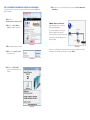
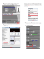
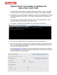
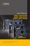
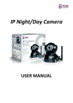
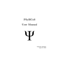
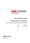
Quick-Start Guide
SUPER DVR
MONITORING
SOFTWARE
Remote Surveillance
& Playback
For use on Q-See’s QSDT series of
PC Securitiy Surveillance Cards
2 CONFIGURING ROUTER FOR REMOTE ACCESS
REMOTE SURVEILLANCE
& PLAYBACK
PART 1: FIND OUT THE IP ADDRESS OF THE SYSTEM
This quick-start guide is excerpted from the Super DVR manual which is available in its entirety
on the CD that accompanied your surveillance video capture card or it can be found on
www.Q-See.com by looking up the model of your card.
1 REMOTE LIVE SURVEILLANCE
Surveillance system supports Remote Surveillance through LAN, Internet, and Intranet. Simply
enable the Webcam function of the system on a computer which is connected to the Internet,
and the computer system will become an Internet Webcam server. On any other computer
that connects to Internet, enter the public IP server address in an Internet Explorer browser
window. Remote users can get high quality real-time image from the server (depending on
available bandwidth) and also control the P.T.Z devices.
STEP 1. To access the router’s settings you will need to enter the Command (CMD)
panel on the computer containing your video capture card.
A. WINDOWS XP – Select Run from
your Windows START menu (lower
left of screen) and type “cmd” after
the prompt.
Microsoft Internet Explorer
Microsoft Office Outlook 2007
iTunes
Default Programs
Adobe Acrobat
Help and Support
HTTP Port - Web service & download
service port, default value is 80.
Data Port - Data transmission port, default
value is 1159.
Run
All Programs
Log Off
start
Inbox Microsof...
B. WINDOWS VISTA and WINDOWS
7 – Click on the START menu
(Windows icon) in the lower left of
your screen. Type “cmd” into the field
that says, “Search programs and
files” and hit ENTER or click on the
magnifying glass icon.
Microsoft Office Outlook 2007
Devices and Printers
Sticky Notes
Default Programs
iTunes
Help and Support
Adobe Acrobat
All Programs
cmd
Shut down
Command Port - Control command port,
default value is 1160.
Picture Quality - Default value is medium.
PICTURE 3
PICTURE 1
If your internet connection does not have enough bandwidth available you can use the Picture
Quality option to send the video over the internet at a lower quality setting then you are using
for recording. That way you will be able to see the images over the internet at lower quality
while still recording at the higher quality setting.
NOTE! The minimum speed on the internet connection is 1Mbps download
and 1Mbps upload for 4 and 8 channels, and 2Mbps download and upload
for 16 channels. You can check the speed of your connection at both ends by
going www.SpeedTest.net from both the computer in which the card is installed as well as
the remote computer which you will be using.
Shut Down
iTunes
PICTURE 2
REMOTE SURVEILLANCE SERVER CONFIGURATION
Users should first enable the Web Camera Services in Basic Configuration and set other
settings as shown below:
Devices and Printers
STEP 2. Type “ipconfig” at the prompt
(Red arrow in Picture 4) to access
router settings.
STEP 3. Write down the IP4v address
(Blue arrow) as well as the Gateway
and Subnet Mask numbers (Green
arrows). The IP4v address is the
address used by the card.
PICTURE 4
PART 2: DETERMINE THE NUMBER OF ROUTERS ON THE NETWORK
To find out the number of routers on your network, you will need to download a FREE router
detection program.
STEP 6. If there is only one router detected, then you may skip to Part 3: Simple Port
Forwarding.
STEP 1. Go to
http://www.pcwintech.com/shanes-toolbox
If Multiple Routers are Detected
STEP 2. Click on Detect Multiple
Routers to begin the download.
If there are multiple routers, you will see a
display similar to Picture 8.
If so, it may be preferable to connect your
DVR and computer to the router that
connects directly to the Internet. However, this
is not always possible depending upon your
particular situation.
STEP 3. Unzip the application to install it.
PICTURE 5
PICTURE 8
In this case, you will need to proceed with the next section using the IP address for Router 1
to forward its ports. After that, you will need to proceed to Part 4.
STEP 4. Click on the detect_routers
application to run it.
PICTURE 6
STEP 5. Click on CHECK NOW to
detect how many Routers are in the
network.
PICTURE 7
PART 3: SIMPLE PORT FORWARDING
STEP 5. Click on ADD CUSTOM.
Download the FREE Simple Port Forwarding program from:
http://www.simpleportforwarding.com/download
STEP 1. Click on Download in any of the mirrors or the Direct Download link to download
and install this program.
PICTURE 9
STEP 2. Once the program is installed,
go to the Windows Start Menu
(Windows icon in the lower left of
your monitor) and look for Simple
Port Forwarding in the program list.
Click on the program to launch it.
PICTURE 12
STEP 6. Input the required information:
PICTURE 10
STEP 3. Once Simple Port Forwarding has launched, select your router from the list.
The default Router IP and Login information will automatically come up. If you have
previously changed the login information, then you will have to enter it manually
Name: (You can name your DVR if you
wish)
Type: TCP
Start Port: 80
End Port:80
IP add: IP of DVR obtained in Part 1.
Click on ADD
Repeat for port 1159 and 1160.
PICTURE 11
STEP 4. Click on “+” at the bottom to open the window allowing you to set your ports.
PICTURE 13
STEP 7. You will now be returned to the main window of the program. The ports you
added will now show on the list. Click on Update Router at the bottom.
If for some reason, a port or ports that you forwarded are not listed in the Router and if you
see a message in the Scripts list on the left side of the window stating that the port already
exists (Red box in Picture 16), then you will need to change the Port 80 to 85 in the DVR
and start over again.
PICTURE 16
PICTURE 14
STEP 8. You will see the “Updating is in progress” message. Please wait until you see it
say DONE at the bottom.
PICTURE 15
STEP 9. Once you receive the DONE message that the ports have been successfully
forwarded, test if the ports are working by clicking on item number 7 in the Check
List - Test that the ports now work.
PICTURE 17
STEP 10. Click on Begin.
PART 4: SETTING UP DMZ IN ROUTER 2
If you receive a message stating that the port is online and can be reached, then you have
set it up correctly.
NOTE! You will only need to proceed with this section if you detected a
second router in Section 2.
STEP 1. Login into Router 1 by putting
the IP of Router 1 into the Internet
Explorer browser, as in the example
shown in Picture 19 where the IP
address of Router 1 is 192.168.0.1
STEP 2. Find the status page on the
router settings that shows the WAN/
Internet IP address and write it down
this WAN IP address.
STEP 3. Log into the Router 2 by putting
the IP of Router 2 into the Internet
Explorer browser, as in example
shown in Picture 19 where the IP
address of Router 2 is 192.168.1.1
STEP 4. Find the DMZ page in the router
settings.
STEP 5. Enter the WAN IP for Router 1
into the DMZ page and enable DMZ.
PICTURE 19
PICTURE 18
To connect to your DVR from the Internet, you will need to put the Internet IP address shown
after “Your Internet Address:” message into your Internet Explorer browser or access program window.
NOTE! The default value is 80. If port 80 is already occupied by another device
on the network, then another port will need to be selected. Choose another
number in the same range; 81-89. In this case, you will have to add the port to
the IP address when entering it into the Internet Explorer window. For example,
if the port is now 82, then you will need to enter http://192.168.0.25:82
IMPORTANT! Do not use 255 or higher to complete your IP address as these
addresses are reserved for other devices and components.
NOTE! If you do not have a DMZ setting in the router, check to see if there
is a Bridge setting. If so, then use the Bridge setting instead of DMZ.
STEP 6. Save your changes.
You have forwarded the ports on the router to which the DVR is connected, to the IP address
of the DVR, and set the primary router to pass the connection to this router.
3 DDNS (DYNAMIC DOMAIN NAME SERVICE)
4 ACCESSING THE DVR USING INTERNET EXPLORER
You can access the system over the Internet using a static or dynamic IP address. However,
your service provider can change this dynamic address from time to time. When it changes,
you will have to return to www.MyIPAaddress.com to get the new public IP address.
There are two solutions to this problem. The first would be to obtain a static IP address from
your ISP – which can be expensive. A second – and free – option is to use a dynamic domain
name service (DDNS) to get a domain name that can be linked to your dynamic IP address. In
addition to automatically keeping up with the changes in the address, you will now be able to
enter a domain name rather than a string of digits when accessing the DVR in Internet Explorer.
Once you have configured the network settings on the DVR to match those on your router
and forwarded the ports needed by the DVR to enable remote access over the Internet, you
will be ready to remotely view your cameras using a webcam program based on an ActiveX
control. For this to work, you will have to enable the ActiveX control options that are built into
Internet Explorer. It is strongly suggested that you be running the latest version of Internet
Explorer (currently IE8). The instructions below will describe the process using that version of
the browser. Instructions for users with IE6 or 7 are available in the Resources library of our
Technical Support page.
We recommend using www.MyQ-See.com or www.DynDNS.com as the DVR has been
already configured to accept account information from these two services.
USER ACCOUNT CONTROL FOR WINDOWS VISTA AND WINDOWS 7
NOTE! Before setting up DDNS, you must have previously set up Port
Forwarding as described in the previous section.
SETTING UP DDNS
Windows Vista
The following instructions are for setting up DDNS with MyQ-See, instructions for DynDNS are
available on their website.
STEP 1. Using a computer that is
connected to the same router as the
DVR, use Internet Explorer to go to
www.MyQ-See.com
STEP 4. Once you have obtained your
domain name, you will need to
configure the DVR for access using it.
STEP 1. Open the Control Panel
(accessible by clicking on the
Windows icon in the lower left of your
screen.
PICTURE 23
STEP 2. Fill out the required information
to register and click the Submit
button at the bottom of the screen.
STEP 3. The next page will ask you
to create a domain name. Domain
names must begin with a letter (a-z)
or a number (0-9) and cannot contain
a hyphen. Once you’ve decided
upon a name, click on the “Request
Domain” button. If it is available you
will see a confirmation screen along
with the IP address associated with it.
Confirm that this matches the number
obtained in Network Settings. Your
domain name will look like this: http://example.myq-see.com
Some users of computers using Windows Vista or Windows 7 operating systems may receive
an error message informing of a codec that is missing or not installed. This conflict can be
resolved by turning off User Account Control (UAC).
STEP 2. Select User Accounts and
Family Safety.
PICTURE 24
PICTURE 20
STEP 3. Select “Add or Remove User
Account.”
PICTURE 25
STEP 4. Select the desired user account.
PICTURE 21
STEP 5. Once you have completed steps 1-4, click on the link on the MyQ-See website
to download the MyQ-See software program onto your computer and install it so that
it can monitor the IP address assigned to your account. The computer must always be
on in order to update the link to the public IP address when it changes.
PICTURE 26
Setting Up ActiveX Control
STEP 5. Select Turn User Account
Control on or off
STEP 1. Open Internet Explorer
STEP 2. Click on Tools
STEP 3. Select Internet Options in the
pull-down menu
PICTURE 27
STEP 6. Uncheck the box next to “Use
User Account Control (UAC) to help
protect your computer.”
PICTURE 31
STEP 4. Click on the Security Tab
STEP 5. Select Trusted Sites
STEP 6. Click on the Sites button
STEP 7. You will then be asked to restart
your computer for the change to take
effect.
PICTURE 32
PICTURE 28
Windows 7
Microsoft Office Outlook 2007
Devices and Printers
STEP 1. Open up the Start Menu
(accessible by clicking on the
Windows icon in the lower left of your
screen.
Adobe Acrobat
STEP 8. Type the DVR’s IP address
(obtained during Network Setup)
or DDNS domain name into the “Add
this website to the zone:” box.
All Programs
STEP 9. Click the Add button
Sticky Notes
Default Programs
iTunes
Help and Support
uac
STEP 2. Type “uac” into the search bar
and hit ENTER. The User Account
Control will open or you will be offered
a link to click to open it.
STEP 7. Uncheck the “Require server
verification (https:) for all sites in
this zone” button.
Shut down
PICTURE 29
STEP 3. Move slider to lowest setting
and press OK.
PICTURE 6-30
STEP 10. Close the window.
PICTURE 33
STEP 11. Click the Custom level…
button.
STEP 13. Click the Reset button
STEP 14. Click “Yes” when asked, “Are
you sure you want to change the
setting for this zone?”
STEP 15. Click OK
STEP 16. Click Apply
STEP 17. Click OK
STEP 18. Close Internet Explorer
PICTURE 6-36
PICTURE 6-34
You are now ready to access the DVR using Internet Explorer.
STEP 12. Pull down the “Reset to:”
menu button and select Low
Open a browser window in Internet Explorer
and enter the IP address or DDNS name
(obtained in Section 6.3 DDNS (Dynamic
Domain Name Service) into the address
bar.
You will see a log in screen similar to that
shown in Picture 37 or yellow alert bar at
the top of the window asking for permission
to open an ActiveX application. Allow it to
install webrec.cab control to reach the
sign-in screen.
Instructions for controlling your system
remotely are in the next section.
PICTURE 6-35
PICTURE 6-37
ACCESSING THE INTERNET EXPLORER CLIENT
After enabling network server on the unit, and enabling ActiveX, users can view the video
from the cameras over the LAN or Internet through Internet Explorer. This unit only supports
Internet Explorer browser, no other browsers are supported. It also supports Win2000, WinXP,
Vista, and Win7.
Input the IP address of the computer with the card if accessing from LAN, or the public IP
address of the router if accessing from the internet, into the Internet Explorer window to reach
the window that prompts you to install the ActiveX control.
Icon
Description
Controls for PTZ Cameras:
Move Up.
Move Down.
Move Left rotate left. Move Right. Stop Rotating.
PTZ ‘Focus’ buttons.
Far Focus
PTZ ‘Zoom’ buttons.
Zoom In
PTZ ‘Iris’ button.
You will get a message asking you to install
the file NetVideo.cab. Install it as normal.
Increase light.
Near Focus
Zoom Out
Decrease light
Go to a Preset Point
Set a Preset Point
Speed dome.
Adjust PTZ speed.
Single channel with full screen display
PICTURE 6-38
Four channel mode - four cameras displayed
Contrast adjustment
You will then be asked to log in. Use the
same User Name and Password as you
would when logging in from the computer
itself. The default User Name is SYSTEM
without a password.
Brightness adjustment
Hue adjustment
Saturation adjustment
Log in/ Log out
Once you have entered the User Name and
Password, click OK to log in.
Record playback
PICTURE 6-39
System Configuration
LAN or Master stream is for users on the same network as
your system. It has higher frame rate and needs higher network
bandwidth
Internet, or sub stream, has a lower frame rate and requires
lower network bandwidth. Users can select the stream
according to their bandwidth.
As you can see, the
WebCam main interface
is very similar to the
SuperDVR main interface.
PICTURE 6-40
5 REMOTE PLAYBACK
Right-clicking the mouse in the main interface
will open a sub menu.
RECORD PLAYBACK AND CONTROL
Open Stream - Click this item, selected
channel will open
Close Stream - Click this item, selected
channel will close
PICTURE 6-41
Click
button on the Webcam main
interface, and the remote playback interface
will appear:
Close All - Click this item, all channels will
close
Full Screen - Select this item, the picture
will display full screen. Double click or
click right mouse to return to the previous
interface.
PICTURE 6-42
Play/ Pause
Stop
Adjust the speed of playing back. Users can adjust play speed as needed.
Playing back backup. Users can click Backup to enter into the Remote
Backup interface:
REMOTE BACKUP
STEP 1. Select the date, channel, then
click Search button. It will list all files
recorded for the day.
STEP 2. Click Browse button, set the
saving path.
STEP 3. Select files in the search area.
Users can hold shift button on the
keyboard and select multi files with
mouse simultaneously.
STEP 4. Click Backup button to do
remote backup.
PICTURE 6-43
The backup files will be saved in AVI format. Most computer users can play with most third
party players directly.
If you do not have a media player installed, we suggest using Windows Media Player Classic
which is available as a free download from many web sites and is easily found via an online
search.
The ruler on top of the bar shows the hours of the day. Right-click the ruler, it will be magnified
10 times allowing users to see the time marks more clearly.
Right-clicking the mouse in the search area
will open a sub menu.
PICTURE 6-44
If you want to view all channels, click Select all, then all check boxes before channels will be
selected.
Click Clear all to clear all selected channels; if users select a certain channel, click Select this
channel, then just this channel be selected.
Click Clear this channel to deselect that channel.
Return to previous main interface
Multiple Channels playback control
The system default playback modes
are single and four channel. If you need
to change to other channels, then click
the single channel button to bring up the
1-channel configuration window where you
can select one channel from all the available
channels for playing back.
PICTURE 6-45
The four channel configuration window
will display when the four channel icon
is selected allowing you to select any four
channels from all the available channels for
play back.
PICTURE 6-46
Data preview shows the recorded data for different channels during corresponding time, the
left side shows the available channels. When a certain channel has been selected for playing
back, the background color will be highlighted, or its dark gray and a tick sign will appear
beside the channel title.
PICTURE 6-47
The data preview area at the center gives details of the recorded files. Different colors of the
bar show different types of records.
BLUE
Manually Recorded
YELLOW
Motion Detection
GREEN
RED
Schedule Recorded
Sensor Alarm
When searching for a certain section of a record, draw the bar to the desired position. If
necessary, right-click the bar to see the magnified time marks for precise search.
You can click the Play button to play the selected record, Then return to live display mode after
finishing remote playback, it will display a message ‘Connecting…’on the screen. And you
may click “Large Picture” or “Quad Picture” button to refresh the screen to get live picture.
For further details on operating your surveillance card and the SuperDVR software, please
consult the complete user manual available at www.Q-See.com or included on the CD that
accompanied your product.
Digital Peripheral Solutions, Inc.
8015 E. Crystal Drive
Anaheim, CA 92807