1
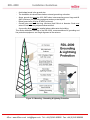
RDL-2000
Broadband Wireless Radio Platform
Installation Guidelines
70-00144-01-01
Proprietary Redline Communications © 2011
Page 1 of 52
March 9, 2011
4Gon www.4Gon.co.uk [email protected] Tel: +44 (0)1245 808295 Fax: +44 (0)1245 808299
RDL-2000
Installation Guidelines
Copyright Information
All rights reserved March 9, 2011. The information in this document is proprietary to
Redline Communications Inc. This document may not in whole or in part be copied,
reproduced, or reduced to any medium without prior consent, in writing, from Redline
Communications Incorporated.
Disclaimer
The statements, configurations, technical data, and recommendations in this document
are believed to be accurate and reliable, but are presented without express or implied
warranty. Additionally, Redline makes no representations or warranties, either expressed
or implied, regarding the contents of this product. Redline Communications shall not be
liable for any misuse regarding this product. The information in this document is subject
to change without notice. No part of this document shall be deemed to be part of any
warranty or contract unless specifically referenced to be part of such warranty or
contract within this document.
70-00144-01-01
Proprietary Redline Communications © 2011
Page 2 of 52
March 9, 2011
4Gon www.4Gon.co.uk [email protected] Tel: +44 (0)1245 808295 Fax: +44 (0)1245 808299
RDL-2000
Installation Guidelines
CONTENTS SUMMARY
70-00144-01-01
1
Important Safety & Service Notices ...................................... 7
1.1
Safety Warnings.................................................................................................7
1.2
Warning Symbols...............................................................................................7
1.3
Service & Warranty Information........................................................................8
1.4
Lightning Protection ..........................................................................................8
1.5
Deployment in the USA and Canada ................................................................9
1.6
FCC & IC Notices ...............................................................................................9
1.7
UL Information .................................................................................................10
1.8
Product Information.........................................................................................10
2
Introduction........................................................................... 11
3
Site Survey Information ....................................................... 12
3.1
RF Interference.................................................................................................12
3.2
Path Profile.......................................................................................................12
3.3
Deployment Information..................................................................................14
4
Installation Procedures ........................................................ 15
4.1
Overview...........................................................................................................15
4.2
Step 1: Assemble Antenna Bracket ................................................................19
4.3
Step 2: RF Connections...................................................................................23
4.4
Step 3: Ethernet Connections .........................................................................27
4.5
Step 4: Installing the RDL-2000.......................................................................31
4.6
Step 6: Antenna Alignment .............................................................................47
5
Reference Information.......................................................... 49
5.1
Protecting Cables from High Temperature & Abrasion.................................49
5.2
Bench Test Setup.............................................................................................50
Proprietary Redline Communications © 2011
Page 3 of 52
March 9, 2011
4Gon www.4Gon.co.uk [email protected] Tel: +44 (0)1245 808295 Fax: +44 (0)1245 808299
RDL-2000
Installation Guidelines
TABLE OF CONTENTS
70-00144-01-01
1
Important Safety & Service Notices ...................................... 7
1.1
Safety Warnings.................................................................................................7
1.2
Warning Symbols...............................................................................................7
1.3
Service & Warranty Information........................................................................8
1.4
Lightning Protection ..........................................................................................8
1.5
Deployment in the USA and Canada ................................................................9
1.6
FCC & IC Notices ...............................................................................................9
1.7
UL Information .................................................................................................10
1.8
Product Information.........................................................................................10
2
Introduction........................................................................... 11
3
Site Survey Information ....................................................... 12
3.1
RF Interference.................................................................................................12
3.2
Path Profile.......................................................................................................12
3.3
Deployment Information..................................................................................14
4
Installation Procedures ........................................................ 15
4.1
4.1.1
4.1.2
4.1.3
Overview...........................................................................................................15
Redline Supplied System Components ...........................................................16
Customer Supplied Materials ..........................................................................17
Installation Overview .......................................................................................18
4.2
4.2.1
Step 1: Assemble Antenna Bracket ................................................................19
Lightweight Mounting Kit .................................................................................19
4.3
4.3.1
4.3.2
4.3.3
4.3.4
Step 2: RF Connections...................................................................................23
RF Ports..........................................................................................................23
RF Cable Connections ....................................................................................24
Connections RF Cables ..................................................................................24
Weatherproofing RF Connectors.....................................................................24
4.4
4.4.1
4.4.2
4.4.3
Step 3: Ethernet Connections .........................................................................27
Ethernet Ports .................................................................................................27
Terminating the Ethernet Cable ......................................................................27
Disconnecting the Ethernet Cable ...................................................................30
4.5
4.5.1
4.5.2
4.5.3
Step 4: Installing the RDL-2000.......................................................................31
Mounting the RDL-2000 ..................................................................................31
System Grounding ..........................................................................................32
Lightning Protection Guidelines.......................................................................32
Grounding Guidelines ..................................................................................32
Installing Ethernet Lightning Arrestors ..........................................................35
Proprietary Redline Communications © 2011
Page 4 of 52
March 9, 2011
4Gon www.4Gon.co.uk [email protected] Tel: +44 (0)1245 808295 Fax: +44 (0)1245 808299
RDL-2000
4.5.4
4.5.5
4.5.6
4.5.7
4.5.8
4.5.9
4.5.10
4.6
4.6.1
Installation Guidelines
Weatherproof LP Connections .....................................................................37
Install Indoor PoE Power Adapter ...................................................................38
Step 5: Configure the RDL-2000 .....................................................................39
List of Required Parameters............................................................................39
Installing the Link Manager Application ...........................................................40
Start a Session with an RDL-2000 ..................................................................40
Configure PTP Slave.......................................................................................41
Configure PTP Master.....................................................................................44
4.6.2
Step 6: Antenna Alignment .............................................................................47
Basic Antenna Alignment ................................................................................47
Antenna Polarization ....................................................................................47
Azimuth Alignment .......................................................................................47
Elevation Alignment .....................................................................................47
Fine Antenna Alignment Using RSSI...............................................................47
5
Reference Information.......................................................... 49
5.1
Protecting Cables from High Temperature & Abrasion.................................49
5.2
5.2.1
5.2.2
5.2.3
5.2.4
Bench Test Setup.............................................................................................50
Customer Supplied Equipment:.......................................................................50
Assemble Test Setup ......................................................................................50
Connectivity Test ............................................................................................50
Throughput Test..............................................................................................51
LIST OF TABLES
Table 1: FCC & IC RF Recommended Safe Separation Distances .................................. 9
Table 2: Site Survey - Site Path Profile Data ................................................................. 13
Table 3: Site Survey - Network Plan Data......................................................................14
Table 4: Site Survey - RF Plan Data ..............................................................................14
Table 5: Site Survey - Additional Parameters ................................................................14
Table 6: Installation - Redline-Supplied Items ................................................................16
Table 7: Installation - Customer-Supplied Items ............................................................17
Table 8: Procedures - Lightweight Mounting Bracket - Parts List ...................................20
Table 9: Installation - Outdoor Ethernet Cable Termination ...........................................28
Table 10: Outdoor Line Protection Wiring Diagram ........................................................36
Table 11: Lightning Protection - Mounting Kit Parts List.................................................36
Table 12: Installation - Step by Step Configuration of RDL-2000 ...................................39
LIST OF FIGURES
Figure 1: Overview - RDL-2000 System Features .........................................................11
Figure 2: Site Survey - Fresnel Zone Radius ................................................................. 12
Figure 3: Site Survey - Non-Line of Sight Deployment ...................................................13
Figure 4: Installation - Redline Supplied Components ...................................................15
Figure 5: Installation - RDL-2000 System Components .................................................18
Figure 6: Procedures - Lightweight Mounting Kit - Installed View...................................19
Figure 7: Procedures - Lightweight Mounting Kit - Bracket Arm .....................................20
Figure 8: Procedures - Lightweight Mounting Kit - Assembly Drawing ...........................21
70-00144-01-01
Proprietary Redline Communications © 2011
Page 5 of 52
March 9, 2011
4Gon www.4Gon.co.uk [email protected] Tel: +44 (0)1245 808295 Fax: +44 (0)1245 808299
RDL-2000
Installation Guidelines
Figure 9: Procedures - Alternate Mounting Methods ......................................................22
Figure 10: Installation - RDL-2000 RF Ports ..................................................................23
Figure 11: Installation - RF Jumper Cable .....................................................................24
Figure 12: Installation - RF Port Weatherproofing - Pt-1 ................................................25
Figure 13: Installation - RF Port Weatherproofing - Pt-2 ................................................25
Figure 14: Installation - RF Port Weatherproofing - Pt-3 ................................................25
Figure 15: Installation - RF Port Weatherproofing - Pt-4 ................................................26
Figure 16: Installation - RDL-2000 Ethernet Ports .........................................................27
Figure 17: Installation - Ethernet Port Cover Plate & Grommet ......................................28
Figure 18: Installation - Ethernet Connector Locking Tab .............................................. 29
Figure 19: Installation - Ethernet Port Weatherproofing .................................................29
Figure 20: Installation - RDL-2000 (with Ethernet Drip Loop) .........................................31
Figure 21: Mounting - Grounding & lightning Protection.................................................33
Figure 22: Mounting - Air Terminal for Tower and Pole Deployments ............................34
Figure 23: Lightning Protection - Terminal Connection Identification .............................35
Figure 24: Lightning Protection - Mounting Kit ...............................................................36
Figure 25: LP Ethernet Cable Entry Weatherproofing - Pt-1 ..........................................37
Figure 26: LP Ethernet Cable Entry Weatherproofing - Pt-2 ..........................................37
Figure 27: LP Ethernet Cable Entry Weatherproofing - Pt-3 ..........................................37
Figure 28: Link Manager - Start Screen .........................................................................40
Figure 29: Link Manager - Slave - Link Configuration Screen ........................................41
Figure 30: Link Manager - Slave - Installation->Advanced Screen ................................. 42
Figure 31: Link Manager - Slave - Installation->Basic Screen ........................................43
Figure 32: Link Manager - Master - Link Configuration Screen ......................................44
Figure 33: Link Manager - Master - Installation->Advanced Screen ...............................45
Figure 34: Link Manager - Master - Installation->Basic Screen ......................................46
Figure 35: Ref. - Outdoor Cable Protection - Spiroband ................................................49
Figure 36: Ref. - Bench Test Setup (No Antenna) .........................................................50
70-00144-01-01
Proprietary Redline Communications © 2011
Page 6 of 52
March 9, 2011
4Gon www.4Gon.co.uk [email protected] Tel: +44 (0)1245 808295 Fax: +44 (0)1245 808299
RDL-2000
Installation Guidelines
Chapter 1
1
1.1
Important Safety & Service
Notices
Safety Warnings
1.
PoE power adapter for RDL-2000:
Warning to Service Personnel: 48 VDC
Customer equipment including personal computers, routers, etc., must be
connected only to the INPUT (DATA) port on the PoE unit.
Only the outdoors Ethernet interface cable connecting to the unit can be safely
connected to the OUTPUT (DATA & POWER OUT) connector. Connecting
customer premises Ethernet equipment directly to the OUTPUT (DATA & POWER
OUT) connector on the Power-over-Ethernet power adapter may damage customer
equipment.
2. Installation of the system must be contracted to a professional installer.
3. The installer is responsible for ensuring that the system is used exclusively for fixed,
4.
5.
6.
7.
8.
9.
10.
1.2
point-to point operations.
Read this user manual and follow all operating and safety instructions.
Keep all product information for future reference.
The power requirements are indicated on the product-marking label. Do not exceed
the described limits.
Disconnect the power before cleaning. Use only a damp cloth for cleaning. Do not
use liquid or aerosol cleaners.
Disconnect power when unit is stored for long periods.
The unit must not be located near power lines or other electrical power circuits.
The system must be properly grounded to protect against power surges and
accumulated static electricity. It is the user’s responsibility to install this device in
accordance with the local electrical codes: correct installation procedures for
grounding the unit, mast, lead-in wire and discharge unit, location of discharge unit,
size of grounding conductors and connection requirements for grounding electrodes.
Warning Symbols
The following symbols may be encountered during installation or troubleshooting. These
warning symbols mean danger. Bodily injury may result if you are not aware of the safety
hazards involved in working with electrical equipment and radio transmitters. Familiarize
yourself with standard safety practices before continuing.
Electro-Magnetic Radiation
70-00144-01-01
Proprietary Redline Communications © 2011
High Voltage
Page 7 of 52
March 9, 2011
4Gon www.4Gon.co.uk [email protected] Tel: +44 (0)1245 808295 Fax: +44 (0)1245 808299
RDL-2000
Installation Guidelines
1.3
Service & Warranty Information
1.4
Lightning Protection
Refer all repairs to qualified service personnel. Do not remove the covers or modify any
part of this device, as this action will void the warranty.
Locate the serial numbers and record these on your registration card for future
reference. Use the space below to affix serial number stickers. Also, record the MAC
address identified on the unit product label.
Redline does not endorse or support the use of outdoor cable assemblies: i) not supplied
by Redline, ii) third-party products that do not meet Redline's cable and connector
assembly specifications, or iii) cables not installed and weatherproofed as specified in
the Installation Guidelines manual (70-00073-01-XX). Refer to the Redline Limited
Standard Warranty and RedCare service agreements.
WARNING: The following notes are general recommendations for the system. The
wireless equipment should be installed by a qualified professional installer who is
knowledgeable of and follows local and national codes for electrical grounding and
safety. Failure to meet safety requirements and/or use of non-standard practices and
procedures could result in personal injury and damage to equipment.
All outdoor wireless equipment is susceptible to lightning damage from a direct hit or
induced current from a near strike. A direct lightning strike may cause serious damage
even if these guidelines are followed. Lightning protection and grounding practices in
local and national electrical codes serve to minimize equipment damage, service
outages, and serious injury. Reasons for lightning damage are summarized as:
a) Poorly grounded antenna sites can conduct high lightning strike energy into
equipment.
b) Lack of properly installed lightning protection equipment can cause equipment
failures from lightning induced currents.
A lighting protection system provides a means by which the energy may enter earth
without passing through and damaging parts of a structure. A lightning protection system
does not prevent lightning from striking; it provides a means for preventing damage to
equipment by providing a low resistance path for the discharge of energy to travel safely
to ground. Improperly grounded connections are also a source of noise that can cause
sensitive equipment to malfunction.
A good grounding system disperses most of the surge energy from a lightning strike
away from the building and equipment. The remaining energy on the Ethernet cable
shield and conductors can be directed safely to ground by installing a lightning arrestor
in series with the cable.
If you have determined that it is appropriate to install lightning protection for your system,
the following general industry practices are provided as a guideline only:
1. The AC wall outlet ground for the indoor POE adapter should be connected to the
building grounding system.
2. Install a lightning arrestor in series with the Ethernet cable at the point of entry to the
building. The grounding wire should be connected to the same termination point
used for the tower or mast.
3. Install a lightning arrestor in series with the Ethernet cable as close to the outdoors
unit as practical. The grounding wire should be connected to the same termination
point used for the tower or mast.
70-00144-01-01
Proprietary Redline Communications © 2011
Page 8 of 52
March 9, 2011
4Gon www.4Gon.co.uk [email protected] Tel: +44 (0)1245 808295 Fax: +44 (0)1245 808299
RDL-2000
4.
1.5
1.6
Installation Guidelines
Provide direct grounding from the unit, the mounting bracket, the antenna, and the
Ethernet cable surge protection to the same ground bus on the building. Use the
grounding screws provided for terminating the ground wires.
Deployment in the USA and Canada
FCC & IC Notices
1.
2.
The Model RDL-2000 and its antenna must be professionally installed.
WARNING -- FCC & IC RF Exposure Warnings
To satisfy FCC and IC RF exposure requirements for RF transmitting devices, the
following distances should be maintained between the antenna of this device and
persons during device operation:
Table 1: FCC & IC RF Recommended Safe Separation Distances
Frequency (GHz)
Mode
Separation Distance
5.4
PTP
40 cm (16 in) or more
5.8
PTP
354 cm (140 in) or more
To ensure compliance, operation at closer than these distances is not
recommended. The antenna used for this transmitter must not be collocated in
conjunction with any other antenna or transmitter.
3. High power radars are allocated as primary users (meaning they have priority) of
5.250-5.350 MHz and 5.650-5.850 GHz and these radars could cause interference
and/or damage to LE-LAN devices.
4. FCC Information to Users @ FCC 15.105:
NOTE: This equipment has been tested and found to comply with the limits for a
Class B digital device, pursuant to part 15 of the FCC Rules. These limits are
designed to provide reasonable protection against harmful interference in a
residential installation.
This equipment generates, uses and can radiate radio frequency energy and, if not
installed and used in accordance with the instructions, may cause harmful
interference to radio communications. However, there is no guarantee that
interference will not occur in a particular installation. If this equipment does cause
harmful interference to radio or television reception, which can be determined by
turning the equipment off and on, the user is encouraged to try to correct the
interference by one or more of the following measures:
- Reorient or relocate the receiving antenna.
- Increase the separation between the equipment and receiver.
- Connect the equipment into an outlet on a circuit different from that to which the
receiver is connected.
- Consult the dealer or an experienced radio/TV technician for help.
Where DFS is required by regional regulations, this function is permanently enabled
at the factory and can not be disabled by the installer or end-user.
5. FCC Information to Users @ FCC 15.21:
Warning: Changes or modifications not expressly approved by Redline
Communications could void the user’s authority to operate the equipment.
70-00144-01-01
Proprietary Redline Communications © 2011
Page 9 of 52
March 9, 2011
4Gon www.4Gon.co.uk [email protected] Tel: +44 (0)1245 808295 Fax: +44 (0)1245 808299
RDL-2000
1.7
UL Information
1. The suitability of the supplied Ethernet cable is subject to the approval of Authority
2.
3.
4.
5.
6.
7.
1.8
Installation Guidelines
Having Jurisdiction and must comply with the local electrical code.
The equipment must be properly grounded according with NEC and other local
safety code and building code requirements
To meet the over-voltage safety requirements on the telecommunications cables, a
minimum 26 AWG telecommunication line cord must be used.
"Pour être en conformance avec les exigences finies de sûreté de sur-tension sur les
câbles de télécommunications un fil de télécommunication ayant un calibre minimum
de 26 AWG doit être utilisé."
Reminder to all the BWA system installers: Attention to Section 820-40 of the NEC
which provides guidelines for proper grounding and, in particular, specifies that the
cable ground shall be connected to the grounding system of the building, as close to
the point of cable entry as is practical.
RDL-2000 must be installed in compliance with relevant articles in National Electrical
Code-NEC (and equivalent Canadian Code-CEC) including referenced articles 725,
800 and 810 in NEC.
RF coaxial cable connecting an antenna to the RDL-2000 must comply with the local
electrical code.
Product Information
Use the following table to record important system information:
Product Information
RDL-2000 SN:
MAC Address
PoE SN:
Model #:
Antenna SN:
Model #
Serial Number Stickers
70-00144-01-01
Proprietary Redline Communications © 2011
Page 10 of 52
March 9, 2011
4Gon www.4Gon.co.uk [email protected] Tel: +44 (0)1245 808295 Fax: +44 (0)1245 808299
RDL-2000
Installation Guidelines
Chapter 2
2
Introduction
The RDL-2000 is a high-performance, high-speed wireless Ethernet bridge for use in a
commercial, industrial, business, or government environment. The system includes a 5.4
- 5.8 GHz radio using a time division duplexing (TDD) RF transceiver to transmit and
receive on the same channel.
Figure 1: Overview - RDL-2000 System Features
The all-outdoor radio is housed in a weatherproof aluminum alloy case and can be used
with external flat panel or parabolic antennas. When equipped with a narrow beam
antenna the RDL-2000 supports long-range operations in clear line of sight (LOS)
conditions. An indoor PoE power adapter provides operational power for the RDL-2000
and connectivity to the local Ethernet network using a standard outdoor approved
Ethernet cable.
For each PTP link, one RDL-2000 is configured as Master Unit (MU) and controls the
wireless link. This function is transparent to all Ethernet operations. The Master uses a
scheduled request/grant mechanism to arbitrate bandwidth requests from the remote
Slave Unit (SU) to provide non contention based traffic with predictable transmission
characteristics. A unique identifier (MU ID) can be specified to ensure wireless links are
established only between designated pairs of RDL-2000 units. Encryption can be
enabled for secure data transmission over the air.
70-00144-01-01
Proprietary Redline Communications © 2011
Page 11 of 52
March 9, 2011
4Gon www.4Gon.co.uk [email protected] Tel: +44 (0)1245 808295 Fax: +44 (0)1245 808299
RDL-2000
Installation Guidelines
Chapter 3
3
3.1
Site Survey Information
Before installing the RDL-2000 equipment, a site survey should be completed and this
data should be available to the installation team. This data will assist the installer to
install the RDL-2000 correctly, and to understand the operating characteristics of the
wireless system during configuration and testing.
RF Interference
Frequency planning is an essential component of installation and it is very important to
test for RF interference at every installation site. The RDL-2000 will not achieve full
operational capability if there is excessive interference.
RF interference may be caused by another wireless system operating on the same RF
channel or adjacent channels. A simple test may be performed using the RDL-2000
built-in Spectrum Sweep feature to determine if a selected RF channel is generally free
from interference. The RDL-2000 also includes an automatic channel selection feature,
to choose the channel with the lowest detected level of interference. Refer to the RDL2000 User Manual for a description of these features.
3.2
Path Profile
The site survey should identify the optimum location for mounting the RDL-2000. For
maximum performance, there should be a direct line of sight between the Master and
Slave system.
Figure 2: Site Survey - Fresnel Zone Radius
The antenna should be positioned to provide maximum clearance within the first Fresnel
zone of the direct path (as high as possible, on either a tall building or tower). A clear
line-of-sight (LOS) path requires clearance above natural and man-made objects by at
least 60% of the First Fresnel zone.
70-00144-01-01
Proprietary Redline Communications © 2011
Page 12 of 52
March 9, 2011
4Gon www.4Gon.co.uk [email protected] Tel: +44 (0)1245 808295 Fax: +44 (0)1245 808299
RDL-2000
Installation Guidelines
The RDL-2000 will also function under optical line-of-sight (OLOS) conditions; where a
clear straight line path exists between the two end points, but the first Fresnel zone is
not clear. If the optical path is completely blocked, it may still be possible to establish a
non line-of-sight (NLOS) path using reflections and diffraction. A satisfactory multipath
RF signal may be obtained by directing both RDL-2000 antennas towards a reflective
structure that is within sight of both units.
Figure 3: Site Survey - Non-Line of Sight Deployment
The path profile should include the following information:
Table 2: Site Survey - Site Path Profile Data
70-00144-01-01
Antenna
Description
Location
Height
Instructions to identify the location for installing the antenna.
May include blueprints and specify material list.
Mounting height for antenna.
Azimuth
Horizontal aiming direction for the antenna (magnetic or GPS compass)
Elevation angle
Vertical aiming for antenna (spirit level).
Expected RSSI
Use the Link Budget tool to determine the expected receive signal
strength indication (RSSI).
Proprietary Redline Communications © 2011
Page 13 of 52
March 9, 2011
4Gon www.4Gon.co.uk [email protected] Tel: +44 (0)1245 808295 Fax: +44 (0)1245 808299
RDL-2000
3.3
Installation Guidelines
Deployment Information
Following installation, each RDL-2000 must be configured for operation with a local
Ethernet network. Contact your network system administrator for details.
The following network and RF plan information is required to configure the wireless link.
Table 3: Site Survey - Network Plan Data
Network
Setting
Master
Plan
IP Address
Slave
Network Mask
Table 4: Site Survey - RF Plan Data
RF
Setting
Master
Slave
Plan
MU ID
(same as Master)
Band
(same as Master)
Channel BW
(same as Master)
M. Tx Power
(same as Master)
Channel/RF Channels
Antenna Gain
Table 5: Site Survey - Additional Parameters
70-00144-01-01
Setting
Description
Ethernet Mode
Speed and duplex options.
VLAN
Necessary if using VLAN for device management.
Proprietary Redline Communications © 2011
Page 14 of 52
March 9, 2011
4Gon www.4Gon.co.uk [email protected] Tel: +44 (0)1245 808295 Fax: +44 (0)1245 808299
RDL-2000
Installation Guidelines
Chapter 4
4
4.1
Installation Procedures
Overview
The components in the following illustration are supplied with each RDL-2000 system.
Figure 4: Installation - Redline Supplied Components
70-00144-01-01
Proprietary Redline Communications © 2011
Page 15 of 52
March 9, 2011
4Gon www.4Gon.co.uk [email protected] Tel: +44 (0)1245 808295 Fax: +44 (0)1245 808299
RDL-2000
4.1.1
Installation Guidelines
Redline Supplied System Components
The following items are provided with each RDL-2000 system. Antenna systems and
lightning protection devices must be ordered separately.
Table 6: Installation - Redline-Supplied Items
Item
Description
1
RDL-2000 Radio
2
Universal mounting bracket with assembly hardware. Bracket adjusts for a 44.5 mm to
76.2 mm (1.75 in to 3.00 in) mast pipe or mounts directly to a flat surface. Assembly is
required.
3
Two 75 cm (29.5 in) RF jumper cables to connect the RDL-2000 to the MIMO antenna
system.
4
30.5 m (100 ft) Cat-5e shielded outdoor Ethernet cable with single RJ-45 connector
termination (indoor connection). The outdoor end of the cable must be terminated by
the installer using the supplied RJ-45 connector (after installing the RDL-2000
Ethernet port weatherproof grommet and mounting plate on the cable).
5
Ethernet port weatherproofing grommet, plate, and mounting screws.
6
RJ- 45 connector for terminating Cat-5 cable.
7
PoE power injector: with single AC 110/220 VAC input, single 10/100 Ethernet data
port, plus single 10/100 powered Ethernet port. Includes AC power cord with type-B
plug.
Quick Start Guide (this document).
8
70-00144-01-01
Proprietary Redline Communications © 2011
Page 16 of 52
March 9, 2011
4Gon www.4Gon.co.uk [email protected] Tel: +44 (0)1245 808295 Fax: +44 (0)1245 808299
RDL-2000
4.1.2
Installation Guidelines
Customer Supplied Materials
Installation of the RDL-2000 equipment requires additional equipment and materials
supplied by the customer. The following list is provided as a guideline only, and
additional materials may be required based on local conditions at each installation site.
This list is not comprehensive and is provided as a guide only.
Table 7: Installation - Customer-Supplied Items
#
Item
Description
1
Equipment Rack
Mounting space allocated for the PoE power adapter. Must
accommodate 2 m (6') AC power cable and routing of Ethernet cable
from PoE to local Ethernet network access point.
2
120/240 VAC
Power
Cat-5 Ethernet
Cables
Cable
Installation
Materials
Reliable 120/240 VAC. Total power requirements must be
evaluated based on individual site configurations.
Connect from PoE power adapter to core network.
5
Radio/Antenna
Mast
Mast or tower location as required by site survey. Equipment must be
rated for weight and wind loading of all installed radios and antennas.
6
Ground Block
Termination for grounding and shield of all conductive cables entering
the building.
7
Grounding
Wire
Master grounding system for all indoor and outdoor equipment,
with #2 AWG through #6 AWG as required and eye-terminals for
connection to RDL-2000 chassis and mounting bracket.
8
Tools
i) Equipment to terminate CAT-5 Ethernet cable with RJ-45 connector
(e.g., AMP 2-231652 or equivalent).
ii) Precision set of screwdrivers, cutter pliers, and other common
installation tools.
iii) Portable computer (Windows™) for RDL-2000 configuration,
antenna alignment, and troubleshooting as required.
3
4
70-00144-01-01
Materials for securing cables to mast, protecting cables from
abrasion, etc. including suggested weatherproofing materials:
Scotch 2200 series of vinyl mastic rolls
Scotch 130C linerless rubber splicing tape
3M Scotch super 88 electrical tape
Rubber mastic putty or duct sealing putty
Proprietary Redline Communications © 2011
Page 17 of 52
March 9, 2011
4Gon www.4Gon.co.uk [email protected] Tel: +44 (0)1245 808295 Fax: +44 (0)1245 808299
RDL-2000
4.1.3
Installation Guidelines
Installation Overview
The following diagram illustrates a typical RDL-2000 installation. When using flat panel
antennas, the RDL-2000 radio and antenna are both secured to the same mounting
bracket. When using parabolic antennas, the radio may be mounted separately. Power
and data are supplied to the RDL-2000 using an outdoor-rated Ethernet cable. The
power injector (PoE) must be located inside a weatherproof enclosure, with access to
reliable AC and connection to the local network. Optional surge arrestor may be ordered
and installed if there are concerns about damage from lightning strikes.
Surge protection must be provided where any outdoor cabling enters a
building. Refer to local building and electrical codes.
Figure 5: Installation - RDL-2000 System Components
70-00144-01-01
Proprietary Redline Communications © 2011
Page 18 of 52
March 9, 2011
4Gon www.4Gon.co.uk [email protected] Tel: +44 (0)1245 808295 Fax: +44 (0)1245 808299
RDL-2000
Installation Guidelines
4.2
Step 1: Assemble Antenna Bracket
4.2.1
Lightweight Mounting Kit
The RDL-2000 lightweight mounting kit general-purpose adapter allows the RDL-2000 to
be mounted on a mast pipe or flat surface. This bracket can be used with Redline flat
panel antennas that mount directly to the radio or with antennas that are mounted
separately (e.g., parabolic antenna).
Figure 6: Procedures - Lightweight Mounting Kit - Installed View
The lightweight installation kit includes:
Universal mounting bracket with assembly hardware. Bracket adjusts for a 44.5 mm
to 76.2 mm (1.75 in to 3.00 in) mast pipe or mounts directly to a flat surface.
Assembly is required.
2. Two 406 mm (16 in) RF jumper cables (N-type connectors, 50 Ohm).
1.
70-00144-01-01
Proprietary Redline Communications © 2011
Page 19 of 52
March 9, 2011
4Gon www.4Gon.co.uk [email protected] Tel: +44 (0)1245 808295 Fax: +44 (0)1245 808299
RDL-2000
Installation Guidelines
Use the following parts list and diagram to assemble the mounting bracket and attach
the RDL-2000 radio and antenna.
Assemble the lightweight mounting bracket. See the following assembly drawings.
2. Attach the RDL-2000 unit directly to the antenna (if applicable).
3. Attach the lightweight mounting bracket to the RDL-2000.
1.
Figure 7: Procedures - Lightweight Mounting Kit - Bracket Arm
Table 8: Procedures - Lightweight Mounting Bracket - Parts List
Item
Qty
Description
Torque
1
1
RDL-2000 Radio*
2
1
Mount Bracket Arm Kit
3
1
Antenna*
4
4
Bolt 1/4-20 UNC X 3/4
13.56 N-m (10 ft-lb.)
5
4
Nut, 1/4-20 UNC
13.56 N-m (10 ft-lb.)
6
8
Washer, 1/4 flat
7
8
Washer, 1/4, split
8
2
230 mm (9 in) RF cables.
N-type connectors, 50 Ohm
12 lb-in (1.35 N-m)
* Item not included in the mounting bracket kit.
70-00144-01-01
Proprietary Redline Communications © 2011
Page 20 of 52
March 9, 2011
4Gon www.4Gon.co.uk [email protected] Tel: +44 (0)1245 808295 Fax: +44 (0)1245 808299
RDL-2000
Installation Guidelines
Figure 8: Procedures - Lightweight Mounting Kit - Assembly Drawing
70-00144-01-01
Proprietary Redline Communications © 2011
Page 21 of 52
March 9, 2011
4Gon www.4Gon.co.uk [email protected] Tel: +44 (0)1245 808295 Fax: +44 (0)1245 808299
RDL-2000
Installation Guidelines
Figure 9: Procedures - Alternate Mounting Methods
70-00144-01-01
Proprietary Redline Communications © 2011
Page 22 of 52
March 9, 2011
4Gon www.4Gon.co.uk [email protected] Tel: +44 (0)1245 808295 Fax: +44 (0)1245 808299
RDL-2000
4.3
Installation Guidelines
Step 2: RF Connections
A pair of RF cables are provided to connect the RDL-2000 to the antenna system. Both
ends of the RF cables must be weatherproofed. This section describes how to connect
the RF cables and the recommended weatherproofing procedures.
: Outdoor Cable Assembly
Redline does not endorse or support the use of outdoor cable assemblies: i) not
supplied by Redline, ii) third-party products that do not meet Redline's cable and
connector assembly specifications, or iii) cables not installed and weatherproofed as
specified in this manual. Redline warranty and service obligations will be voided under
the conditions listed above. Refer to the Redline Limited Standard Warranty and
RedCare service agreements for details.
4.3.1
RF Ports
The RF ports (2x female TNC connectors) are used to conduct RF signals between the
RDL-2000 and the antenna system. Refer to Figure 10: Installation - RDL-2000 RF Ports
for the port locations.
RF Port 0: This port is always active. Use RF Port 0 when deploying a SISO (single
antenna) system.
RF Port 1: This port is activated when MIMO operation is enabled in the system
configuration.
Figure 10: Installation - RDL-2000 RF Ports
Note: When deploying a MIMO system, it is not required to match the antenna
connections (RF Port 0/ RF Port 1) between the antenna systems at each end of the
wireless link.
70-00144-01-01
Proprietary Redline Communications © 2011
Page 23 of 52
March 9, 2011
4Gon www.4Gon.co.uk [email protected] Tel: +44 (0)1245 808295 Fax: +44 (0)1245 808299
RDL-2000
4.3.2
Installation Guidelines
RF Cable Connections
Two RF jumper cables are provided with each RDL-2000 unit. The RF cables conduct
RF signals between the RDL-2000 and antenna system. Each 75 cm (29.5 in) cable is
terminated female BNC to Type-N.
Figure 11: Installation - RF Jumper Cable
4.3.3
Connections RF Cables
Apply a small amount of weatherproofing grease to weatherproof the connector threads
on each RF cable. Connect the RF cables between the RDL-2000 RF ports and the
antenna RF ports. The connectors must be finger-tight only. Using excessive force or the
incorrect tools will damage the connectors on the antenna and RDL-2000 and defeat the
connector weatherproofing features.
Outdoor Cable Assembly Weatherproofing
The TNC-type connectors on the RDL-2000 and the antenna must be weatherproofed.
This section provides a pictorial primer on correct weatherproofing procedures.
Redline does not recommend silicon seal or glue as these materials are difficult to
apply accurately, can leave gaps, and are difficult to remove. Do not use PVC tape.
4.3.4
Weatherproofing RF Connectors
The importance of proper weatherproofing can not be overstressed. Inadequate
weatherproofing can result in damage to equipment and higher maintenance costs. Both
ends of the RF cable must be weatherproofed.
The following sealing tapes are recommended for weatherproofing:
- Scotch 2200 series of Vinyl Mastic rolls
- Scotch 130C Linerless Rubber Splicing Tape
- 3M Scotch Super 88 Electrical Tape
These are heavy-duty weather, abrasion, and UV resistant tapes that can be purchased
at most hardware stores. Rubber mastic putty or duct sealing putty must also be used to
complete the weatherproofing. The professional installer may use his own
weatherproofing materials provided they are not silicon-based.
70-00144-01-01
Proprietary Redline Communications © 2011
Page 24 of 52
March 9, 2011
4Gon www.4Gon.co.uk [email protected] Tel: +44 (0)1245 808295 Fax: +44 (0)1245 808299
RDL-2000
Installation Guidelines
1. Begin to wrap the splicing tape. Start as close as possible to the chassis.
Figure 12: Installation - RF Port Weatherproofing - Pt-1
2. Stretch and wind the tape back along the connector housing making very sure there
are no gaps in the tape.
Figure 13: Installation - RF Port Weatherproofing - Pt-2
3. Continue to wrap the tape tightly along the cable.
Figure 14: Installation - RF Port Weatherproofing - Pt-3
70-00144-01-01
Proprietary Redline Communications © 2011
Page 25 of 52
March 9, 2011
4Gon www.4Gon.co.uk [email protected] Tel: +44 (0)1245 808295 Fax: +44 (0)1245 808299
RDL-2000
Installation Guidelines
4. When the taping is complete, work the mastic putty well into the area between the
connector and the body of the radio. Continue working the putty to make a watertight
seal.
Figure 15: Installation - RF Port Weatherproofing - Pt-4
The connection is now well weatherproofed. Repeat this procedure for each RF
connector on the RDL-2000 and the antenna system.
70-00144-01-01
Proprietary Redline Communications © 2011
Page 26 of 52
March 9, 2011
4Gon www.4Gon.co.uk [email protected] Tel: +44 (0)1245 808295 Fax: +44 (0)1245 808299
RDL-2000
4.4
Installation Guidelines
Step 3: Ethernet Connections
An outdoor Ethernet cable is provided to connect the RDL-2000 to the local network.
This section describes how to connect and weatherproof the Ethernet cable.
Important -- RDL-2000 Ethernet Cables
The maximum total length of the Ethernet cable is 100 m (328 ft). For example, 98 m
(322 ft) from the RDL-2000 to the PoE and an additional 2 m (6 ft) from the PoE to the
network equipment.
4.4.1
Ethernet Ports
The RDL-2000 has two Ethernet ports (female RJ-45 connectors) used to receive DC
power from the PoE and exchange data with the local Ethernet network. The ports
provide identical functions. Refer to Figure 16: Installation - RDL-2000 Ethernet Ports for
the port locations.
Ethernet Port 1: This port is sealed at the factory. Use Ethernet Port 2.
Ethernet Port 2: Use this Ethernet port for normal operation.
The RDL-2000 Ethernet port uses a custom pinout for the PoE signals. All
Ethernet cables from the indoor PoE to the outdoor RDL-2000 must be terminated to
match the specifications in this manual.
Figure 16: Installation - RDL-2000 Ethernet Ports
4.4.2
Terminating the Ethernet Cable
The outdoor Ethernet cable is supplied with a single RJ-45 connector for terminating to
the indoor PoE. The system installer must prepare this cable by:
1. Install the Ethernet port weatherproof grommet and clamp onto the cable.
2. Terminate the cable using the supplied RJ-45 connector.
3. Connect the cable to the RDL-2000 Ethernet port.
4. Weatherproof the RDL-2000 Ethernet port.
70-00144-01-01
Proprietary Redline Communications © 2011
Page 27 of 52
March 9, 2011
4Gon www.4Gon.co.uk [email protected] Tel: +44 (0)1245 808295 Fax: +44 (0)1245 808299
RDL-2000
Installation Guidelines
The Ethernet cable must be inserted through the mounting plate and grommet
before the RJ-45 connector is installed on outdoor Ethernet cable.
When assembled correctly, the Ethernet port seal will be weather-resistant.
Use the following steps to:
1. Install the Ethernet port weatherproof grommet and clamp onto the cable.
a. Insert the grommet into the grommet clamping plate. The grommet must be
threaded through the metal clamping plate first. This operation will not be
possible after the Ethernet cable has been inserted through the grommet.
b. Thread the Ethernet cable through the rubber grommet/metal clamping plate
combination (see Figure 17). The large end of the grommet should be
oriented towards the unterminated end of the cable.
Figure 17: Installation - Ethernet Port Cover Plate & Grommet
2. Terminate the cable using the supplied RJ-45 connector. The RDL-2000 Ethernet
port uses a custom pinout for the PoE signals. All Ethernet cables from the
indoor PoE to the outdoor RDL-2000 must be terminated to match the
specifications in Table 9.
Table 9: Installation - Outdoor Ethernet Cable Termination
RJ-45 Conn.
Signal
1
RX +
Color Code
White / Orange
Identification
2
Rx -
Orange
3
Tx +
White / Green
4
No Connection
5
No Connection
6
Tx -
Green
7
+Ve
Blue
8
-Ve
Brown
Note: Color codes are provided for convenience only. All signals must match the
connector assignments. Do not terminate wires to pins 4 an d 5 on the RJ-45
connector.
70-00144-01-01
Proprietary Redline Communications © 2011
Page 28 of 52
March 9, 2011
4Gon www.4Gon.co.uk [email protected] Tel: +44 (0)1245 808295 Fax: +44 (0)1245 808299
RDL-2000
Installation Guidelines
3. Connect the cable to the RDL-2000 Ethernet port by inserting the RJ-45 plug into
the mating RDL-2000 Ethernet port connector.
Ethernet Plug Must 'Click' into Socket
Inserting the RJ-45 plug into the mating socket should result in an audible 'click'
from the locking mechanism. Ensure the connector is locked in position. Do not
use cables where the locking tab is broken or has been removed!
Figure 18: Installation - Ethernet Connector Locking Tab
It is strongly recommended to test the Ethernet cable by connecting
the RDL-2000 to a PoE and verifying connectivity (e.g., ping from a connected
PC) before sealing and weatherproofing the RDL-2000.
4. Weatherproof the RDL-2000 Ethernet port.
Position the grommet and clamping plate against the Ethernet port opening and
install the two NC-6 screws with spring washers to seal the port (see Figure 19).
Figure 19: Installation - Ethernet Port Weatherproofing
Apply adequate weatherproofing (putty and tape) to protect the Ethernet ports. While the
Ethernet connection is weatherproof, it is always advisable to provide additional
weatherproofing. Use the same procedure as for the RF cable connections (refer to
section 4.3.4: Weatherproofing RF Connectors on page 24).
70-00144-01-01
Proprietary Redline Communications © 2011
Page 29 of 52
March 9, 2011
4Gon www.4Gon.co.uk [email protected] Tel: +44 (0)1245 808295 Fax: +44 (0)1245 808299
RDL-2000
4.4.3
Installation Guidelines
Disconnecting the Ethernet Cable
The RJ-45 connector is recessed within the RDL-2000 chassis. To disconnect the
Ethernet cable from the RDL-2000, you must use a small flat blade screwdriver or similar
tool release the locking tab located in the chassis recess.
1. Use a small flat blade screwdriver or similar tool to carefully depress the locking tab
on the Ethernet plug.
2. Maintain pressure on the tab and use only a light pull (two fingers) to remove the
Ethernet plug from the socket. The cable must be pulled straight out the port or the
connector may be caught on the chassis metal housing.
Ethernet Cable Removal
Use of excessive force when removing the Ethernet cable will damage the RJ-45
connector and the RDL-2000 printed circuit board.
If the weatherproofing grommet has been installed, care must be taken to avoid
excessive strain on the RJ-45 connector when moving the grommet to gain access the
release pin on the connector. Be sure to push the Ethernet cable through the grommet
hole as the grommet is moved away from the RDL-2000 port.
70-00144-01-01
Proprietary Redline Communications © 2011
Page 30 of 52
March 9, 2011
4Gon www.4Gon.co.uk [email protected] Tel: +44 (0)1245 808295 Fax: +44 (0)1245 808299
RDL-2000
4.5
Installation Guidelines
Step 4: Installing the RDL-2000
This section describes mounting the RDL-2000, recommendations for grounding and line
protection equipment, and basic antenna alignment.
RDL-2000 Installation Guidelines
The following are general guidelines for system installation. The RDL-2000 must be
installed by a qualified professional installer and follow local and national building codes
and codes for electrical grounding and safety.
Failure to meet safety requirements and/or use of non-standard practices and
procedures could result in personal injury and damage to equipment. A direct lightning
hit may cause serious damage or injury even if these guidelines are followed for the
system. A direct lightning hit may cause serious damage or injury even if these
guidelines are followed for the system.
Do not install outdoor components during adverse weather conditions when the threat
of a lightning strike is possible.
4.5.1
Mounting the RDL-2000
It is recommended to pre-assemble and test the RDL-2000 equipment (RDL2000, mounting bracket, and antenna) and connection wiring before final installation of
the units. Refer to 5.2: Bench Test Setup on page 50.
The standard mounting kit may be used with 305 or 370 mm (12 or 14.5 in) flat panel
antennas where the RDL-2000 is installed on towers or similar locations. The mounting
bracket adjusts to fit 4.45 mm to 11.73 cm (1.75 in to 4.62 in) mast pipe.
Figure 20: Installation - RDL-2000 (with Ethernet Drip Loop)
All RDL-2000 systems should be installed with an Ethernet cable drip loop to reduce
mechanical strain on the RDL-2000 Ethernet port. A drip loop should also be used when
mounting lightning protection devices to avoid mechanical stress and excess water flow
at the Ethernet wiring ports.
70-00144-01-01
Proprietary Redline Communications © 2011
Page 31 of 52
March 9, 2011
4Gon www.4Gon.co.uk [email protected] Tel: +44 (0)1245 808295 Fax: +44 (0)1245 808299
RDL-2000
4.5.2
Installation Guidelines
System Grounding
A grounding connection is located on the RDL-2000 chassis. Use this screw to terminate
a grounding wire.
System Grounding Procedures
Correct grounding is very important for safe operation of wireless equipment -- ensure
that all grounding connections are made in accordance with local and national
standards.
The following general industry practices are provided as a guideline only:
1. All grounding connections must be made in accordance with local and national
standards. Painted or dirty surfaces should be cleaned thoroughly down to bare
metal and screws should be well tightened.
2. Provide a direct ground connection from the antenna-mounting bracket, the RDL2000 unit, and any lightning protection equipment, to the same ground point on the
tower. Use the grounding screw on the antenna bracket and the grounding screw on
the RDL-2000 to terminate the ground wires. Avoid making sharp bends in the
ground wires.
4.5.3
Lightning Protection Guidelines
All outdoor wireless equipment is susceptible to lightning damage. Lightning protection
and grounding practices per the local and national electrical codes serve to minimize
possible equipment damage, service outages, and serious injury. Common reasons for
these damages can be summarized as follows:
- Tower/Antenna sites that are not grounded properly may conduct high lightning strike
energy.
- Lack of installed lightning protection equipment may cause equipment failures
resulting from lightning induced currents.
The grounding system should provide a low-impedance path to ground for the lightninginduced current. A loose ground connection is a source of noise and may cause
sensitive equipment to malfunction.
The tower grounding system disperses most of the surge energy from a tower strike
away from the building and equipment. The remaining energy on the Ethernet cable
shield and center conductor can be directed safely to ground by using a lightning
arrestor in series with the Ethernet cable.
Grounding Guidelines
The following are general recommendations for system installation.
This equipment must be installed by a qualified professional installer and follow
local and national codes for electrical grounding and safety. Failure to meet
safety requirements and/or use of non-standard practices and procedures could
result in personal injury and damage to equipment. A direct lightning hit may
cause serious damage or i njury even if these guidelines are followed for the
system.
The following general industry practices are provided as a guideline only.
- All grounding connections must be made in accordance with local/national
standards.
- Painted or dirty surfaces should be cleaned thoroughly down to bare metal and
screws should be well tightened.
70-00144-01-01
Proprietary Redline Communications © 2011
Page 32 of 52
March 9, 2011
4Gon www.4Gon.co.uk [email protected] Tel: +44 (0)1245 808295 Fax: +44 (0)1245 808299
RDL-2000
Installation Guidelines
-
Avoid sharp bends in the ground wire.
The installation site should have had an external ground ring or bus bar.
Above ground wire must be #2-6 AWG when interconnecting ground rings and #6
AWG (minimum) for grounding equipment and any metal objects
- Below ground wire must be #2 AWG (minimum).
- Ground rods must be 8 feet long (minimum) and 5/8-inch in diameter. Rods must
extend 3 feet below any adjacent basement/vault.
- A grounding block should be installed where cables enter the building.
This section describes mounting of the RDL-2000, recommendations for grounding and
line protection equipment, and rough alignment of the antenna.
Figure 21: Mounting - Grounding & lightning Protection
70-00144-01-01
Proprietary Redline Communications © 2011
Page 33 of 52
March 9, 2011
4Gon www.4Gon.co.uk [email protected] Tel: +44 (0)1245 808295 Fax: +44 (0)1245 808299
RDL-2000
Installation Guidelines
The following recommendations are general industry practices:
-
-
-
-
-
The antenna mast/tower must be connected to the master earth ground.
It is recommended to pre-assemble and test the RDL-2000 equipment (RDL2000, mounting bracket, and antenna) and connection wiring before final
installation of the units. Mount the pre-assembled RDL-2000 on the antenna
mast.
Direct grounding from the RDL-2000, the mounting bracket, the antenna, and
the Ethernet cable surge protection to the same ground bus on the building
should be provided. Terminate ground wires using the grounding screws
provided on the RDL-2000 and the antenna mounting bracket.
A lightning arrestor should be installed in series with the Ethernet cable as
close to the RDL-2000 unit as practical. The grounding wire should be
connected to the same termination point used for the tower or mast.
A lightning arrestor should be installed in series with the Ethernet cable at the
point of entry to the building. The grounding wire should be connected to the
same termination point used for the tower or mast.
. If AC PoE is used, the AC wall outlet ground for the indoor POE adapter
should be connected to the building grounding system.
Figure 22: Mounting - Air Terminal for Tower and Pole Deployments
70-00144-01-01
Proprietary Redline Communications © 2011
Page 34 of 52
March 9, 2011
4Gon www.4Gon.co.uk [email protected] Tel: +44 (0)1245 808295 Fax: +44 (0)1245 808299
RDL-2000
Installation Guidelines
Installing Ethernet Lightning Arrestors
If you have determined that it is appropriate to install lightning protection for your system,
the following general industry practices are provided as a guideline only:
Installing the Line Protector Unit
This section describes the steps required to install the Ethernet line protector. It is
recommended to pre-wire the LP device and test all connections before final outdoor
installation. Connect the LP unit according to the direction it is labeled. Each side of the
unit has been labeled SURGE and PROTECTED for this purpose. Do not switch
Ethernet wires from input to output. The unit may be mounted/grounded on a nearby
plate or bulkhead panel that is bonded to an earth-ground system.
Installing the POE Line Protector Unit
Do not install during adverse weather conditions when the threat of a
lightning strike is possible.
Connect this unit in the direction it is labeled. E ach side of the unit has been labeled
SURGE and PROTECTED for this purpose. Do not switch Ethernet wires coming in and
going out. Fo r –IG (isolated ground) units, they are marked 2 X FEED and 2 X RTN
(RETURN). T he unit may be mounted/grounded on a nearby plate or bulkhead panel
that is bonded to an earth-ground system.
1. Mounting: Ground the unit with provided 2 X 8-32 screws to the pattern below.
2. Terminal Block:
Wire gauge; 16-28 AWG. Wire strip length; 0.25”. Tightening
torque; 2.21 lb-in. (0.25 N-m).
3. Lid: 4 X M4 X 20 mm screws. Be sure the neoprene gasket on the lid is not loose and
is properly fitted into the groove. Tightening torque; 11 lb-in. (1.24 N-m).
Outdoor Units: Be sure all conduit fittings are used and torqued to meet environmental
specifications. Conduit fittings have O-rings to ensure environmental seal.
FOR CORRECT OPERATION, IT IS VERY IMPORTANT THAT THE
LINE PROTECTOR IS PROPERLY CONNECTED TO A LOW IMPEDANCE (LOW R
AND LOW L) GROUND SYSTEM.
Figure 23: Lightning Protection - Terminal Connection Identification
Note: LP terminal block assignment is identical for both screw-type and 110Connect.
70-00144-01-01
Proprietary Redline Communications © 2011
Page 35 of 52
March 9, 2011
4Gon www.4Gon.co.uk [email protected] Tel: +44 (0)1245 808295 Fax: +44 (0)1245 808299
RDL-2000
Installation Guidelines
Table 10: Outdoor Line Protection Wiring Diagram
Terminal Block (TB)
Signal
Color Code
Wire Color
1
Rx +
White / Orange
2
Rx -
Orange
3
Tx +
White / Green
4
Tx -
Green
5
48 (+)
Blue
6
48 (+)
White/Blue
7
48 (-)
White/Brown
8
48 (-)
Brown
Line Protector Mast Mounting Kit
This kit is used for mounting the lightning protector to a 76 - 127 mm (3-5 in) diameter pole.
Note: The Polyphaser IX-Pole-Kit kit is not available directly from Redline, and must be
ordered separately (if required) from a telecom equipment distributor.
1. Align box cover plate (1) mounting holes (Pemstuds facing out) with mounting holes on the
LP box.
2. Insert screws (2) through the LP box and cover (1), secure with #8 washer (5) and nut (4).
3. Attach bracket (3) onto Pemstuds of assembly cover (1) using #10 washer (7) and nut (6).
4. Slide hose clamp (8) through both slotted grooves of bracket (3), attach hose clamp to pole.
Figure 24: Lightning Protection - Mounting Kit
Table 11: Lightning Protection - Mounting Kit Parts List
Item
70-00144-01-01
Description
Qty.
Item
Description
Qty.
1
Assm Bracket
1
5
Washer #8 int.
2
2
Screw 8-32 x 0.5
2
6
Nut #10
2
3
Bracket Mnl Dbl Bend
1
7
Washer #10
2
4
Nut #8
2
8
Clamp Hose 3-5 in.
1
Proprietary Redline Communications © 2011
Page 36 of 52
March 9, 2011
4Gon www.4Gon.co.uk [email protected] Tel: +44 (0)1245 808295 Fax: +44 (0)1245 808299
RDL-2000
Installation Guidelines
Weatherproof LP Connections
It is important to weatherproof both ends of the line protection unit.
1. Begin to wrap the splicing tape. Start as close to the LP housing as possible. Stretch
and wind the tape back along the connector housing making very sure there are no
gaps in the tape.
Figure 25: LP Ethernet Cable Entry Weatherproofing - Pt-1
2. Continue to wrap the tape tightly along the cable.
Figure 26: LP Ethernet Cable Entry Weatherproofing - Pt-2
3. Work the mastic putty into the area between the connector and the body of the LP.
Continue to work the putty in making a watertight seal. The connection is now well
weatherproofed.
Figure 27: LP Ethernet Cable Entry Weatherproofing - Pt-3
Repeat this procedure for both cable connections to the LP.
70-00144-01-01
Proprietary Redline Communications © 2011
Page 37 of 52
March 9, 2011
4Gon www.4Gon.co.uk [email protected] Tel: +44 (0)1245 808295 Fax: +44 (0)1245 808299
RDL-2000
4.5.4
Installation Guidelines
Install Indoor PoE Power Adapter
The indoor Power-over-Ethernet (PoE) power adapter provides operational power and
the Ethernet connection to the RDL-2000. The PoE is auto-sensing 110-240 VAC. A
grounded AC outlet must be provided within about one meter of the PoE adapter
mounting location. The AC power cable is supplied with a grounding power plug. Do not
defeat this important safety feature.
The indoor end of the Redline supplied Ethernet cable is terminated with a non-hooded
RJ-45 connector. This connects to the OUTPUT (DATA & POWER) port of the indoor
PoE power adapter. The minimum diameter conduit or hole required is 18 mm (11/16 in).
The power block provides two Ethernet interfaces:
INPUT (DATA):
Connection to local network equipment.
OUTPUT (DATA & POWER):
Signal and power to the RDL-2000.
Warning to Service Personnel: 48 VDC
Customer equipment including personal computers, routers, etc., must be connected
only to the INPUT (DATA) port on the PoE unit. Only the outdoors Ethernet interface
cable connecting to the RDL-2000 can be safely connected to the OUTPUT (DATA &
POWER) connector. Connecting customer premises Ethernet equipment directly to
the OUTPUT (DATA & POWER) connector on the Power-over-Ethernet power
adapter may damage customer equipment.
70-00144-01-01
Proprietary Redline Communications © 2011
Page 38 of 52
March 9, 2011
4Gon www.4Gon.co.uk [email protected] Tel: +44 (0)1245 808295 Fax: +44 (0)1245 808299
RDL-2000
4.5.5
4.5.6
Installation Guidelines
Step 5: Configure the RDL-2000
This step describes using the system configuration and monitoring options available
using the Redline Link Manager application. This application provides all settings
necessary to configure, monitor, and troubleshoot operation of the RDL-2000 wireless
link. The operator can access and control the RDL-2000 locally or remotely using IP
connectivity over the network connection. The CLI interface is a general monitoring tool
and does not include all commands necessary to setup and monitor the RDL-2000.
List of Required Parameters
The following table summarizes the steps required to configure the RDL-2000 unit.
Parameters must be configured in the stated order. Enter all parameter settings on each
screen and then click the Submit button to save these changes. If the unit automatically
reboots, start a new session and continue with the next step. Changing screens without
clicking the Submit button will discard all changes made in that screen.
The RDL-2000 must have a license file installed before placing unit in-service.
After changing the license file, you must exit and re-start the Link Manager application.
Table 12: Installation - Step by Step Configuration of RDL-2000
Step
1
2
Screen
License
Link
Config
Parameter
License File
Reference
1
Channel BW
Unit Type
2
Advanced
PTP Slave
Enable
Enable
MU ID
RF Plan
N/A
SU MAC Address
MAC Address
N/A
Channel
Network Plan
N/A
Enable ACS
Disable
N/A
Activate ATPC
Enable
Enable
Enable
N/A
RF Plan
Adaptive Modulation
Installation
PTP Master
RF Plan
2
Band
4
Slave
MAC Address
Enable MIMO
3
Master
Antenna Gain
RF Plan
M. Tx Power
RF Plan
IP Address
Network Plan
Subnet Mask
Network Plan
MU ID
Network Plan
N/A
RF Channels
RF plan
N/A
1. After changing the license file, you must exit and re-start the Link Manager
application.
2. When changing the Unit Type and/or Channel BW, you must click the Submit
Parameters button to make these changes active before continuing with the
configuration setup. The RDL-2000 unit will reboot.
70-00144-01-01
Proprietary Redline Communications © 2011
Page 39 of 52
March 9, 2011
4Gon www.4Gon.co.uk [email protected] Tel: +44 (0)1245 808295 Fax: +44 (0)1245 808299
RDL-2000
4.5.7
Installation Guidelines
Installing the Link Manager Application
The Link Manager application must be installed using the installer provided on CD-ROM.
1. Insert the CD-ROM into the PC, browse to the CD and double-click on the program:
Link_Manager_V1_000x.exe
2. Follow on-screen instructions to install the Link Manager.
Note: Windows™ 7 users must install WinPcap v4.1.1 before installing Link Manager.
4.5.8
Start a Session with an RDL-2000
1. Use a standard Ethernet cable to connect the PC directly to the PoE Data In port. It
is not required to know the IP address of the RDL-2000.
2. Click Tools->Select Adapter and select the applicable LAN Ethernet interface.
3. Click S on the command bar (or press CTRL-S) to start a session. Click to highlight
the RDL-2000 in the pop-up dialog. Select user type Admin, enter the password
admin, and click Login to begin a session.
Note: It the login is not successful, review the status messages in the Link Manager log.
Refer to the RDL-2000 User Manual for detailed information about Link Manager
features and operation.
Figure 28: Link Manager - Start Screen
70-00144-01-01
Proprietary Redline Communications © 2011
Page 40 of 52
March 9, 2011
4Gon www.4Gon.co.uk [email protected] Tel: +44 (0)1245 808295 Fax: +44 (0)1245 808299
RDL-2000
4.5.9
Installation Guidelines
Configure PTP Slave
The following instructions must be performed in the order listed. The configuration listed
here is to facilitate installation only. Refer to your detailed RF plan for any other required
parameter settings.
Start the Link Manager (Start-> Link_Manager-> Link_Manager), click 'S' on
the toolbar to start a session, and login as Admin.
2. Display the License screen and Drag & Drop the licence file for this MAC
address onto the license screen. Click Submit to activate the license. The
RDL-2000 will automatically reboot.
Important: Exit from the Link Manager after changing the license file, and
then re-start the Link manager application to load the new RDL-2000 settings.
3. PTP Slave Link Configuration Screen
a. Channel BW (see RF plan).
b. Enable MIMO = (Enabled)
c. Unit Type = PTP Slave
d. Click Submit Parameters (RDL-2000 may automatically reboot).
1.
Figure 29: Link Manager - Slave - Link Configuration Screen
70-00144-01-01
Proprietary Redline Communications © 2011
Page 41 of 52
March 9, 2011
4Gon www.4Gon.co.uk [email protected] Tel: +44 (0)1245 808295 Fax: +44 (0)1245 808299
RDL-2000
4.
Installation Guidelines
PTP Slave Advanced Screen
a. Activate ATPC =
(Enabled)
b. Band (see RF plan).
c. Antenna Gain (see RF plan).
d. M. Tx Power (max. Tx Power) (see RF plan).
e. Click Submit (RDL-2000 may automatically reboot).
Figure 30: Link Manager - Slave - Installation->Advanced Screen
70-00144-01-01
Proprietary Redline Communications © 2011
Page 42 of 52
March 9, 2011
4Gon www.4Gon.co.uk [email protected] Tel: +44 (0)1245 808295 Fax: +44 (0)1245 808299
RDL-2000
Installation Guidelines
PTP Slave Installation Screen
a. IP Address (RF plan).
b. Subnet Mask (RF plan).
c. MU ID (RF plan).
d. RF Channel Scan: Disable selected RF channels if required (RF plan).
e. Click Submit (RDL-2000 may automatically reboot).
6. Click RU or select menu item Action->Reset Unit to reboot the RDL-2000.
7. Initial configuration of the PTP Slave is now complete. Proceed to the
configuration of the PTP Master.
5.
Figure 31: Link Manager - Slave - Installation->Basic Screen
70-00144-01-01
Proprietary Redline Communications © 2011
Page 43 of 52
March 9, 2011
4Gon www.4Gon.co.uk [email protected] Tel: +44 (0)1245 808295 Fax: +44 (0)1245 808299
RDL-2000
Installation Guidelines
4.5.10 Configure PTP Master
The following instructions must be performed in the order listed. The configuration listed
here is to facilitate installation only. Refer to your detailed RF plan for any other required
parameter settings.
Start the Link Manager (Start-> Link_Manager-> Link_Manager), click 'E' on
the toolbar to start a session and login as Admin.
2. Display the License screen and Drag & Drop the licence file for this MAC
address onto the license screen. Click Submit to activate the license. The
RDL-2000 will automatically reboot.
Important: Exit from the Link Manager after changing the license file, and
then re-start the Link manager application to load the new RDL-2000 settings.
3. PTP Master Link Configuration Screen
a. Channel BW: This must match the slave unit (RF plan).
b. Enable MIMO:
(Enabled)
c. Unit Type = PTP Master
Important: If the unit is currently a PTP Slave, you must click Submit to
reboot the unit in PTP Master mode before continuing the setup.
d. MU ID: Enter SU ID of connected slave unit (RF Plan).
e. SU MAC Address: Enter MAC of connected slave unit.
f. Channel: Select the required RF channel from the list (RF Plan).
g. Enable ACS:
(Enabled).
h. Click Submit Parameters (RDL-2000 may automatically reboot)
1.
Figure 32: Link Manager - Master - Link Configuration Screen
70-00144-01-01
Proprietary Redline Communications © 2011
Page 44 of 52
March 9, 2011
4Gon www.4Gon.co.uk [email protected] Tel: +44 (0)1245 808295 Fax: +44 (0)1245 808299
RDL-2000
4.
Installation Guidelines
PTP Master Advanced Screen
a. Activate ATPC:
(Enabled)
b. Band: Must match slave unit (RF plan).
c. Adaptive Modulation:
(Enabled)
d. Antenna Gain: See RF plan.
e. M. Tx Power: See RF plan.
f. Click Submit (RDL-2000 may automatically reboot).
Figure 33: Link Manager - Master - Installation->Advanced Screen
70-00144-01-01
Proprietary Redline Communications © 2011
Page 45 of 52
March 9, 2011
4Gon www.4Gon.co.uk [email protected] Tel: +44 (0)1245 808295 Fax: +44 (0)1245 808299
RDL-2000
Installation Guidelines
PTP Master Installation Screen
a. IP Address See RF Plan.
b. Subnet Mask See RF Plan.
c. Click Submit (unit may automatically reboot).
6. Click RU or select menu item Action->Reset Unit to reboot RDL-2000.
7. Initial configuration of the PTP Master and PTP Slave is now complete.
Proceed to the antenna alignment section.
5.
Figure 34: Link Manager - Master - Installation->Basic Screen
70-00144-01-01
Proprietary Redline Communications © 2011
Page 46 of 52
March 9, 2011
4Gon www.4Gon.co.uk [email protected] Tel: +44 (0)1245 808295 Fax: +44 (0)1245 808299
RDL-2000
Installation Guidelines
4.6
Step 6: Antenna Alignment
4.6.1
Basic Antenna Alignment
Correct antenna alignment is essential in obtaining the maximum performance from the
wireless link. A misaligned antenna will result in decreased receive signal strength and
you may be unable to establish the wireless link.
The alignment must be performed in both the azimuth and elevation planes. Before
installing the equipment, obtain accurate antenna pointing azimuth and elevation angles
for each installation site (see section 0:
Site Survey Information on page 12). This will allow approximate alignment of antennas
by using GPS or magnetic compass.
Antenna Polarization
The same antenna polarization must be used for both RDL-2000 units in a SISO (single
antenna system) PTP link. The arrows on the rear of the antenna indicate the
polarization.
Azimuth Alignment
Use a magnetic or GPS compass to obtain the approximate azimuth direction. Note that
a metal tower will affect the accuracy of a magnetic compass. Magnetic declination (the
difference between true North and Magnetic North) must also be taken onto account.
The azimuth is aligned by loosening the bolts on the pipe bracket and rotating the
antenna around the pole. To adjust the azimuth, loosen the four bolts identified in the
figure on this page.
Elevation Alignment
Most links will have an elevation of zero degrees. The antenna can be set vertically (to a
close approximation) using a bubble (spirit) level. This method is not accurate for
elevation settings of greater than 5 degrees.
To adjust the elevation, loosen the four bolts identified in the figure on this page.
4.6.2
Fine Antenna Alignment Using RSSI
The RDL-2000 must be connected to the Ethernet PoE adapter and configured before
the antenna alignment can be completed.
Antenna adjustments can also be made based on RSSI measurements reported by the
RDL-2000. The RSSI information is available using the built in audible antenna
alignment tool (Buzzer) or using the Link Manager application.
Slowly adjust the antenna elevation, and then azimuth in a broad sweeping pattern,
while observing the peaks and valleys in the RSSI readings.
While sweeping the antenna, the RSSI value will rise when aligned to a sidelobe, and
then fall and rise to the highest reading when the receiver is properly aligned to the main
beam. Further movement of the antenna will cause the RSSI to fall and then rise to a
lower peak when aligned to another sidelobe.
70-00144-01-01
Proprietary Redline Communications © 2011
Page 47 of 52
March 9, 2011
4Gon www.4Gon.co.uk [email protected] Tel: +44 (0)1245 808295 Fax: +44 (0)1245 808299
RDL-2000
Installation Guidelines
When the alignment sweep has been completed, the measured RSSI value should be
checked against the estimated value obtained from the link budget. If the wireless link is
LOS, the measured RSSI value should be within 5 dBm of the calculated value.
A lower or fluctuating RSSI value may indicate that the antenna is aligned to a sidelobe.
If the RSSI value is much lower than the link budget prediction, this may indicate an
optical LOS or non-LOS path. If the link is non-LOS, a suitable reflecting surface such as
a building or billboard must be used. For non-LOS deployments, it is necessary to install
the link and perform vertical and horizontal sweeps of the antenna to determine if the
required throughput can be achieved.
When the alignment is complete, tighten bolts to 13.5 n-m (10 ft-lbs). Tighten each bolt
in a cross-pattern to minimize shifts in the antenna alignment.
70-00144-01-01
Proprietary Redline Communications © 2011
Page 48 of 52
March 9, 2011
4Gon www.4Gon.co.uk [email protected] Tel: +44 (0)1245 808295 Fax: +44 (0)1245 808299
RDL-2000
Installation Guidelines
Chapter 5
5
5.1
Reference Information
Protecting Cables from High Temperature &
Abrasion
Temperature and abrasion may damage the outdoor cables and lead to a degradation in
service. It is recommended to review the following information about protecting outdoor
cables. In extremely hot climates, the outdoor cable may be degraded when the
temperature of the metal tower structure exceeds the maximum specified cable rating. In
windy climates, excessive abrasion may damage the cables.
Redline recommends the use of suitable diameter spiral bound sleeve (generically called
'spiroband') to protect the outdoor cable. This product should be available from most
local electrical suppliers.
Figure 35: Ref. - Outdoor Cable Protection - Spiroband
Wrap the sleeve around the outdoor cable for at least 300 mm (~12 in) in each direction
from bonding points and any other area the cable is in direct contact with the metal
tower. Cable ties can be used in the normal way to secure the cable.
70-00144-01-01
Proprietary Redline Communications © 2011
Page 49 of 52
March 9, 2011
4Gon www.4Gon.co.uk [email protected] Tel: +44 (0)1245 808295 Fax: +44 (0)1245 808299
RDL-2000
Installation Guidelines
5.2
Bench Test Setup
5.2.1
Customer Supplied Equipment:
Windows™ computer with Redline 'Link Manager' application installed.
2. Second computer is preferred to perform link data testing.
3. Pair of RF attenuators (70 dB recommended) for indoor testing.
4. AC power (for PoE).
1.
Figure 36: Ref. - Bench Test Setup (No Antenna)
Note: The default IP address is 192.168.25.2. The default Admin password is: admin. To
avoid Layer-2 loops, only one RDL-2000 should be connected to a local LAN.
5.2.2
5.2.3
Assemble Test Setup
Connect the units as shown in the diagram and power on all equipment.
2. Transfer the RDL-2000 license files to PC#1 and PC#2.
1.
Connectivity Test
1.
2.
3.
4.
5.
6.
70-00144-01-01
On PC #1, go to the Ping screen. Set the test for 1024 byte packets,
transmitted each 1000 ms, to address 192.168.25.2 (slave unit).
Click the Start button and observe that the slave unit is responding.
Click the Stop button to terminate the ping test.
Set the test for 5000 byte packets, transmitted each 1000 ms, to address
192.168.25.20 (PC #2).
Click the Start button and observe that that PC #2 is responding.
Click the Stop button to terminate the ping test.
Proprietary Redline Communications © 2011
Page 50 of 52
March 9, 2011
4Gon www.4Gon.co.uk [email protected] Tel: +44 (0)1245 808295 Fax: +44 (0)1245 808299
RDL-2000
5.2.4
70-00144-01-01
Installation Guidelines
Throughput Test
On PC #1, go to the Throughput Test screen. Set the address to
192.168.25.20 (PC #2), set the data rate to 10 Mbps, and click the Start
button to begin transmitting data.
2. On PC #2, go to the Throughput Test screen and click the Rx button to start
listening for data. Observe that the Rx counter adjacent to the Rx button
indicates that data is being received and the rate is approximately 10 Mbps.
3. On PC #1, adjust the slider to increase the data rate and observe that PC #2
is correctly receiving at the same rate.
4. Click the End button on both PCs to stop the throughput test.
1.
Proprietary Redline Communications © 2011
Page 51 of 52
March 9, 2011
4Gon www.4Gon.co.uk [email protected] Tel: +44 (0)1245 808295 Fax: +44 (0)1245 808299
70-00144-01-01
Proprietary Redline Communications © 2011
Page 52 of 52
March 9, 2011
4Gon www.4Gon.co.uk [email protected] Tel: +44 (0)1245 808295 Fax: +44 (0)1245 808299