1
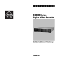
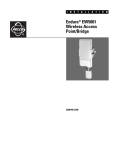
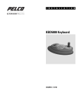
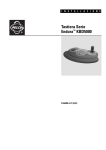
I N S T A L L A T I O N
Endura
NVR5100 Series
Network Video Recorder
®
C1621M-E (9/08)
Contents
Regulatory Notices . . . . . . . . . . . . . . . . . . . . . . . . . . . . . . . . . . . . . . . . . . . . . . . . . . . . . . . . . . . . . . . . . . . . . . . . . . . . . . . . . . . . . . . . . . . . . . . . . . . . 5
Description . . . . . . . . . . . . . . . . . . . . . . . . . . . . . . . . . . . . . . . . . . . . . . . . . . . . . . . . . . . . . . . . . . . . . . . . . . . . . . . . . . . . . . . . . . . . . . . . . . . . . . . . . . 6
Features . . . . . . . . . . . . . . . . . . . . . . . . . . . . . . . . . . . . . . . . . . . . . . . . . . . . . . . . . . . . . . . . . . . . . . . . . . . . . . . . . . . . . . . . . . . . . . . . . . . . . . . . 6
Models . . . . . . . . . . . . . . . . . . . . . . . . . . . . . . . . . . . . . . . . . . . . . . . . . . . . . . . . . . . . . . . . . . . . . . . . . . . . . . . . . . . . . . . . . . . . . . . . . . . . . . . . . 7
Optional Accessories . . . . . . . . . . . . . . . . . . . . . . . . . . . . . . . . . . . . . . . . . . . . . . . . . . . . . . . . . . . . . . . . . . . . . . . . . . . . . . . . . . . . . . . . . . . . . . 7
Before You Begin . . . . . . . . . . . . . . . . . . . . . . . . . . . . . . . . . . . . . . . . . . . . . . . . . . . . . . . . . . . . . . . . . . . . . . . . . . . . . . . . . . . . . . . . . . . . . . . . . . . . . 8
Parts List . . . . . . . . . . . . . . . . . . . . . . . . . . . . . . . . . . . . . . . . . . . . . . . . . . . . . . . . . . . . . . . . . . . . . . . . . . . . . . . . . . . . . . . . . . . . . . . . . . . . . . . 8
User-Supplied Parts . . . . . . . . . . . . . . . . . . . . . . . . . . . . . . . . . . . . . . . . . . . . . . . . . . . . . . . . . . . . . . . . . . . . . . . . . . . . . . . . . . . . . . . . . . . . . . . 9
Package Contents . . . . . . . . . . . . . . . . . . . . . . . . . . . . . . . . . . . . . . . . . . . . . . . . . . . . . . . . . . . . . . . . . . . . . . . . . . . . . . . . . . . . . . . . . . . . . . . 10
Integration and Application Scenario . . . . . . . . . . . . . . . . . . . . . . . . . . . . . . . . . . . . . . . . . . . . . . . . . . . . . . . . . . . . . . . . . . . . . . . . . . . . . . . . 12
Equipment Placement and Rack Mounting . . . . . . . . . . . . . . . . . . . . . . . . . . . . . . . . . . . . . . . . . . . . . . . . . . . . . . . . . . . . . . . . . . . . . . . . . . . . . . . . . 13
Unpacking the NVR5100 . . . . . . . . . . . . . . . . . . . . . . . . . . . . . . . . . . . . . . . . . . . . . . . . . . . . . . . . . . . . . . . . . . . . . . . . . . . . . . . . . . . . . . . . . . 13
Product Serial Number Label Placement . . . . . . . . . . . . . . . . . . . . . . . . . . . . . . . . . . . . . . . . . . . . . . . . . . . . . . . . . . . . . . . . . . . . . . . . . . . . . . 13
Desktop Installation . . . . . . . . . . . . . . . . . . . . . . . . . . . . . . . . . . . . . . . . . . . . . . . . . . . . . . . . . . . . . . . . . . . . . . . . . . . . . . . . . . . . . . . . . . . . . . 14
Rack Mounting . . . . . . . . . . . . . . . . . . . . . . . . . . . . . . . . . . . . . . . . . . . . . . . . . . . . . . . . . . . . . . . . . . . . . . . . . . . . . . . . . . . . . . . . . . . . . . . . . . 15
Hard Drive Array Installation . . . . . . . . . . . . . . . . . . . . . . . . . . . . . . . . . . . . . . . . . . . . . . . . . . . . . . . . . . . . . . . . . . . . . . . . . . . . . . . . . . . . . . . . . . . 20
Installing Hard Drive Carriers . . . . . . . . . . . . . . . . . . . . . . . . . . . . . . . . . . . . . . . . . . . . . . . . . . . . . . . . . . . . . . . . . . . . . . . . . . . . . . . . . . . . . . 20
Connections . . . . . . . . . . . . . . . . . . . . . . . . . . . . . . . . . . . . . . . . . . . . . . . . . . . . . . . . . . . . . . . . . . . . . . . . . . . . . . . . . . . . . . . . . . . . . . . . . . . . . . . . 23
Connecting Power . . . . . . . . . . . . . . . . . . . . . . . . . . . . . . . . . . . . . . . . . . . . . . . . . . . . . . . . . . . . . . . . . . . . . . . . . . . . . . . . . . . . . . . . . . . . . . . 23
Connecting to the Network . . . . . . . . . . . . . . . . . . . . . . . . . . . . . . . . . . . . . . . . . . . . . . . . . . . . . . . . . . . . . . . . . . . . . . . . . . . . . . . . . . . . . . . . 24
Operation . . . . . . . . . . . . . . . . . . . . . . . . . . . . . . . . . . . . . . . . . . . . . . . . . . . . . . . . . . . . . . . . . . . . . . . . . . . . . . . . . . . . . . . . . . . . . . . . . . . . . . . . . . 25
Front Panel Controls and Indicators . . . . . . . . . . . . . . . . . . . . . . . . . . . . . . . . . . . . . . . . . . . . . . . . . . . . . . . . . . . . . . . . . . . . . . . . . . . . . . . . . . 25
Unit Startup . . . . . . . . . . . . . . . . . . . . . . . . . . . . . . . . . . . . . . . . . . . . . . . . . . . . . . . . . . . . . . . . . . . . . . . . . . . . . . . . . . . . . . . . . . . . . . . . . . . . 26
Unit Shutdown . . . . . . . . . . . . . . . . . . . . . . . . . . . . . . . . . . . . . . . . . . . . . . . . . . . . . . . . . . . . . . . . . . . . . . . . . . . . . . . . . . . . . . . . . . . . . . . . . . 27
Troubleshooting . . . . . . . . . . . . . . . . . . . . . . . . . . . . . . . . . . . . . . . . . . . . . . . . . . . . . . . . . . . . . . . . . . . . . . . . . . . . . . . . . . . . . . . . . . . . . . . . . . . . . 28
NVR5100 . . . . . . . . . . . . . . . . . . . . . . . . . . . . . . . . . . . . . . . . . . . . . . . . . . . . . . . . . . . . . . . . . . . . . . . . . . . . . . . . . . . . . . . . . . . . . . . . . . . . . . 28
Power Supply . . . . . . . . . . . . . . . . . . . . . . . . . . . . . . . . . . . . . . . . . . . . . . . . . . . . . . . . . . . . . . . . . . . . . . . . . . . . . . . . . . . . . . . . . . . . . . . . . . . 28
Specifications . . . . . . . . . . . . . . . . . . . . . . . . . . . . . . . . . . . . . . . . . . . . . . . . . . . . . . . . . . . . . . . . . . . . . . . . . . . . . . . . . . . . . . . . . . . . . . . . . . . . . . . 29
Appendices . . . . . . . . . . . . . . . . . . . . . . . . . . . . . . . . . . . . . . . . . . . . . . . . . . . . . . . . . . . . . . . . . . . . . . . . . . . . . . . . . . . . . . . . . . . . . . . . . . . . . . . . . 31
Appendix A: Expanding Video Storage . . . . . . . . . . . . . . . . . . . . . . . . . . . . . . . . . . . . . . . . . . . . . . . . . . . . . . . . . . . . . . . . . . . . . . . . . . . . . . . 31
Installing a Single SEB5100 Unit (Cable) . . . . . . . . . . . . . . . . . . . . . . . . . . . . . . . . . . . . . . . . . . . . . . . . . . . . . . . . . . . . . . . . . . . . . . . . . 31
Installing Multiple SEB5100 Units (Switch) . . . . . . . . . . . . . . . . . . . . . . . . . . . . . . . . . . . . . . . . . . . . . . . . . . . . . . . . . . . . . . . . . . . . . . . 32
Installing Additional SEB5100 Units (Existing Switch) . . . . . . . . . . . . . . . . . . . . . . . . . . . . . . . . . . . . . . . . . . . . . . . . . . . . . . . . . . . . . . . 33
Appendix B: Replacing a Hard Drive . . . . . . . . . . . . . . . . . . . . . . . . . . . . . . . . . . . . . . . . . . . . . . . . . . . . . . . . . . . . . . . . . . . . . . . . . . . . . . . . . 33
Appendix C: Replacing a Power Supply . . . . . . . . . . . . . . . . . . . . . . . . . . . . . . . . . . . . . . . . . . . . . . . . . . . . . . . . . . . . . . . . . . . . . . . . . . . . . . . 35
Appendix D: Installing an Uninterruptible Power Supply (UPS) . . . . . . . . . . . . . . . . . . . . . . . . . . . . . . . . . . . . . . . . . . . . . . . . . . . . . . . . . . . . 37
C1621M-E (9/08)
3
List of Illustrations
1
2
3
4
5
6
7
8
9
10
11
12
13
14
15
16
17
18
19
20
21
22
23
24
25
26
27
28
29
30
31
32
33
4
Major Package Components. . . . . . . . . . . . . . . . . . . . . . . . . . . . . . . . . . . . . . . . . . . . . . . . . . . . . . . . . . . . . . . . . . . . . . . . . . . . . . . . . . . . . . . . 10
Hard Drive Pack. . . . . . . . . . . . . . . . . . . . . . . . . . . . . . . . . . . . . . . . . . . . . . . . . . . . . . . . . . . . . . . . . . . . . . . . . . . . . . . . . . . . . . . . . . . . . . . . . . 10
Accessory Pack . . . . . . . . . . . . . . . . . . . . . . . . . . . . . . . . . . . . . . . . . . . . . . . . . . . . . . . . . . . . . . . . . . . . . . . . . . . . . . . . . . . . . . . . . . . . . . . . . . 11
Rack Mount Kit . . . . . . . . . . . . . . . . . . . . . . . . . . . . . . . . . . . . . . . . . . . . . . . . . . . . . . . . . . . . . . . . . . . . . . . . . . . . . . . . . . . . . . . . . . . . . . . . . . 11
Enterprise-Wide Security Network. . . . . . . . . . . . . . . . . . . . . . . . . . . . . . . . . . . . . . . . . . . . . . . . . . . . . . . . . . . . . . . . . . . . . . . . . . . . . . . . . . . 12
Unpacking the NVR5100 Series . . . . . . . . . . . . . . . . . . . . . . . . . . . . . . . . . . . . . . . . . . . . . . . . . . . . . . . . . . . . . . . . . . . . . . . . . . . . . . . . . . . . . 13
Product Serial Number Label . . . . . . . . . . . . . . . . . . . . . . . . . . . . . . . . . . . . . . . . . . . . . . . . . . . . . . . . . . . . . . . . . . . . . . . . . . . . . . . . . . . . . . . 14
Installing Rubber Feet and Removing Brackets . . . . . . . . . . . . . . . . . . . . . . . . . . . . . . . . . . . . . . . . . . . . . . . . . . . . . . . . . . . . . . . . . . . . . . . . . 14
Fastening Mounting Brackets to Chassis . . . . . . . . . . . . . . . . . . . . . . . . . . . . . . . . . . . . . . . . . . . . . . . . . . . . . . . . . . . . . . . . . . . . . . . . . . . . . . 15
Assembling a Support Rail . . . . . . . . . . . . . . . . . . . . . . . . . . . . . . . . . . . . . . . . . . . . . . . . . . . . . . . . . . . . . . . . . . . . . . . . . . . . . . . . . . . . . . . . . 16
Inserting Cage Nuts . . . . . . . . . . . . . . . . . . . . . . . . . . . . . . . . . . . . . . . . . . . . . . . . . . . . . . . . . . . . . . . . . . . . . . . . . . . . . . . . . . . . . . . . . . . . . . 16
Attaching Support Rails . . . . . . . . . . . . . . . . . . . . . . . . . . . . . . . . . . . . . . . . . . . . . . . . . . . . . . . . . . . . . . . . . . . . . . . . . . . . . . . . . . . . . . . . . . . 17
Attaching Rack Rail Spacers. . . . . . . . . . . . . . . . . . . . . . . . . . . . . . . . . . . . . . . . . . . . . . . . . . . . . . . . . . . . . . . . . . . . . . . . . . . . . . . . . . . . . . . . 18
Mounting the NVR5100 into the Rack . . . . . . . . . . . . . . . . . . . . . . . . . . . . . . . . . . . . . . . . . . . . . . . . . . . . . . . . . . . . . . . . . . . . . . . . . . . . . . . . 18
Tightening the Thumbscrews . . . . . . . . . . . . . . . . . . . . . . . . . . . . . . . . . . . . . . . . . . . . . . . . . . . . . . . . . . . . . . . . . . . . . . . . . . . . . . . . . . . . . . . 19
Opening the Front Bezel . . . . . . . . . . . . . . . . . . . . . . . . . . . . . . . . . . . . . . . . . . . . . . . . . . . . . . . . . . . . . . . . . . . . . . . . . . . . . . . . . . . . . . . . . . . 20
Drive Bay Assignment. . . . . . . . . . . . . . . . . . . . . . . . . . . . . . . . . . . . . . . . . . . . . . . . . . . . . . . . . . . . . . . . . . . . . . . . . . . . . . . . . . . . . . . . . . . . . 21
Hard Disk Drive Carrier Installation . . . . . . . . . . . . . . . . . . . . . . . . . . . . . . . . . . . . . . . . . . . . . . . . . . . . . . . . . . . . . . . . . . . . . . . . . . . . . . . . . . 21
Checking Hard Disk Drive Carrier . . . . . . . . . . . . . . . . . . . . . . . . . . . . . . . . . . . . . . . . . . . . . . . . . . . . . . . . . . . . . . . . . . . . . . . . . . . . . . . . . . . . 22
Rear Panel Layout . . . . . . . . . . . . . . . . . . . . . . . . . . . . . . . . . . . . . . . . . . . . . . . . . . . . . . . . . . . . . . . . . . . . . . . . . . . . . . . . . . . . . . . . . . . . . . . . 23
Network Cable Connection. . . . . . . . . . . . . . . . . . . . . . . . . . . . . . . . . . . . . . . . . . . . . . . . . . . . . . . . . . . . . . . . . . . . . . . . . . . . . . . . . . . . . . . . . 24
Front Panel Layout . . . . . . . . . . . . . . . . . . . . . . . . . . . . . . . . . . . . . . . . . . . . . . . . . . . . . . . . . . . . . . . . . . . . . . . . . . . . . . . . . . . . . . . . . . . . . . . 25
Front Bezel Indicators . . . . . . . . . . . . . . . . . . . . . . . . . . . . . . . . . . . . . . . . . . . . . . . . . . . . . . . . . . . . . . . . . . . . . . . . . . . . . . . . . . . . . . . . . . . . . 25
Opening the Front Bezel . . . . . . . . . . . . . . . . . . . . . . . . . . . . . . . . . . . . . . . . . . . . . . . . . . . . . . . . . . . . . . . . . . . . . . . . . . . . . . . . . . . . . . . . . . . 26
Connecting an NVR5100 Directly to an SEB5100. . . . . . . . . . . . . . . . . . . . . . . . . . . . . . . . . . . . . . . . . . . . . . . . . . . . . . . . . . . . . . . . . . . . . . . . 31
Connecting an NVR5100 to Multiple SEB5100 Units. . . . . . . . . . . . . . . . . . . . . . . . . . . . . . . . . . . . . . . . . . . . . . . . . . . . . . . . . . . . . . . . . . . . . 32
Operating the Latching Mechanism . . . . . . . . . . . . . . . . . . . . . . . . . . . . . . . . . . . . . . . . . . . . . . . . . . . . . . . . . . . . . . . . . . . . . . . . . . . . . . . . . . 33
Removing the Hard Drive Carrier . . . . . . . . . . . . . . . . . . . . . . . . . . . . . . . . . . . . . . . . . . . . . . . . . . . . . . . . . . . . . . . . . . . . . . . . . . . . . . . . . . . . 34
Installing the Hard Drive Carrier. . . . . . . . . . . . . . . . . . . . . . . . . . . . . . . . . . . . . . . . . . . . . . . . . . . . . . . . . . . . . . . . . . . . . . . . . . . . . . . . . . . . . 34
Releasing the Power Supply Latching Mechanism . . . . . . . . . . . . . . . . . . . . . . . . . . . . . . . . . . . . . . . . . . . . . . . . . . . . . . . . . . . . . . . . . . . . . . 35
Removing the Power Supply. . . . . . . . . . . . . . . . . . . . . . . . . . . . . . . . . . . . . . . . . . . . . . . . . . . . . . . . . . . . . . . . . . . . . . . . . . . . . . . . . . . . . . . . 36
Installing the Power Supply . . . . . . . . . . . . . . . . . . . . . . . . . . . . . . . . . . . . . . . . . . . . . . . . . . . . . . . . . . . . . . . . . . . . . . . . . . . . . . . . . . . . . . . . 36
Connecting a UPS to an NVR5100 . . . . . . . . . . . . . . . . . . . . . . . . . . . . . . . . . . . . . . . . . . . . . . . . . . . . . . . . . . . . . . . . . . . . . . . . . . . . . . . . . . . 37
C1621M-E (9/08)
Regulatory Notices
This device complies with Part 15 of the FCC Rules. Operation is subject to the following two conditions: (1) this device may not cause harmful
interference, and (2) this device must accept any interference received, including interference that may cause undesired operation.
RADIO AND TELEVISION INTERFERENCE
This equipment has been tested and found to comply with the limits of a Class A digital device, pursuant to Part 15 of the FCC Rules. These limits
are designed to provide reasonable protection against harmful interference when the equipment is operated in a commercial environment. This
equipment generates, uses, and can radiate radio frequency energy and, if not installed and used in accordance with the instruction manual, may
cause harmful interference to radio communications. Operation of this equipment in a residential area is likely to cause harmful interference in
which case the user will be required to correct the interference at his own expense.
Changes and modifications not expressly approved by the manufacturer or registrant of this equipment can void your authority to operate this
equipment under Federal Communications Commission’s rules.
In order to maintain compliance with FCC regulations shielded cables must be used with this equipment. Operation with non-approved
equipment or unshielded cables is likely to result in interference to radio and television reception.
This Class A digital apparatus complies with Canadian ICES-003.
Cet appareil numérique de la classe A est conforme à la norme NMB-003 du Canada.
Video Quality Caution
FRAME RATE NOTICE REGARDING USER-SELECTED OPTIONS
Pelco systems are capable of providing high quality video for both live viewing and playback. However, the systems can be used in lower quality
modes, which can degrade picture quality, to allow for a slower rate of data transfer and to reduce the amount of video data stored. The picture
quality can be degraded by either lowering the resolution, reducing the picture rate, or both. A picture degraded by having a reduced resolution
may result in an image that is less clear or even indiscernible. A picture degraded by reducing the picture rate has fewer frames per second,
which can result in images that appear to jump or move more quickly than normal during playback. Lower frame rates may result in a key event
not being recorded by the system.
Judgment as to the suitability of the products for users’ purposes is solely the users’ responsibility. Users shall determine the suitability of the
products for their own intended application, picture rate and picture quality. In the event users intend to use the video for evidentiary purposes in
a judicial proceeding or otherwise, users should consult with their attorney regarding any particular requirements for such use.
C1621M-E (9/08)
5
Description
The NVR5100 Series network video recorder (NVR) represents a new generation of flexibility and integration for network-based video system
recording. It is one of the recording components of Endura®, Pelco’s most advanced integrated video security system. The NVR represents the
state of the art in scalability, performance, expandability, and reliability. It is ideally suited for mission-critical, enterprise surveillance
applications.
The NVR5100 Series recorder is capable of continuous, scheduled, alarm/event, and motion recording. Pre- and post-alarm recording is also
available. All recording is fully programmable on a per-channel basis.
The unit includes EnduraStor™ to maximize storage efficiency. EnduraStor improves upon traditional time-lapse recording to achieve longer video
retention. While time-lapse recording records everything at a low frame rate, EnduraStor records in real-time for a user-defined delay period.
During the delay period, all real-time, high frame rate video is available for search, playback, and export. After the delay period, EnduraStor
reduces video from a high frame rate to a lower frame rate. EnduraStor does not reduce alarm and event video.
Designed with reliability in mind, the NVR5100 Series provides performance enhancement and fault tolerance by employing RAID 5 disk
management across as many as 12 hard drives. The NVR incorporates two RAID 5 controllers, each managing six hard drives.
NOTE: The NVR5100 Series recorder supports hot-swappable hard drives in case of failure; it does not support hot hard drive expansion.
Dual redundant, hot-swappable power supplies add another layer of reliability to the unit. Support for matrix-enabled failover rounds out the
reliability aspects of the NVR5100. Diagnostics are systemized with other Endura products so that problems are reported to various network
infrastructure-monitoring systems.
The NVR5100 Series recorder is the network-based video recording system of the future. It integrates seamlessly with Pelco’s integrated security
products to create a robust, secure, and expandable security platform. When combined with Pelco’s Endura workstation and stand-alone user
interfaces, the NVR5100 Series becomes a powerful search, retrieval, and archival audio/video system. EnduraStor makes real-time video
available when users need it most while keeping storage costs under control.
FEATURES
6
•
Supports up to 48 cameras at 30 frames per second (fps), 4CIF resolution (NVR5148)
•
Supplies up to 32 simultaneous playback streams and up to 10 simultaneous queries
•
iSCSI-based expandable storage capacity using Pelco’s storage expansion boxes (SEB5100 Series)
•
Plug-and-play configuration
•
Data authentication at time of recording
•
Output viewable on up to 32 individual workstations
•
Records video, audio, and data streams for every channel
•
EnduraStor storage management system
•
Hot-swappable hard drives and power supplies
•
Fault tolerance and performance enhanced through use of RAID 5
•
Redundant power supplies
•
Storage locking
•
Fully compatible with Pelco’s integrated system architecture
•
System diagnostics and error logging
•
Full over-the-network remote control and administration
C1621M-E (9/08)
MODELS
Streams*
Drives
Internal
Storage
Video
Storage
24
6†
1.5 TB
1.16 TB
NVR5124-3000
24
†
6
3.0 TB
2.32 TB
NVR5124-6000
24
12
6.0 TB
4.65 TB
NVR5124-9000
24
12
9.0 TB
6.98 TB
48
†
1.5 TB
1.16 TB
†
Models
NVR5124-1500
NVR5148-1500
6
NVR5148-3000
48
6
3.0 TB
2.32 TB
NVR5148-6000
48
12
6.0 TB
4.65 TB
NVR5148-9000
48
12
9.0 TB
6.98 TB
*Simultaneous full frame rate/full resolution input streams.
†
All six-drive models include six empty hard drive carriers.
OPTIONAL ACCESSORIES
SEB5100 Series
Each SEB5100 Series storage expansion box adds 1.5 TB to 9.0 TB of external storage, including 1.16 TB to 6.98 TB of
video storage, to any NVR5100 network video recorder. Up to eight units can be connected to an NVR5100 for a maximum
of 62.8 TB of available video storage.
Drives
Internal
Storage
Video
Storage
Up to 48
6†
1.5 TB
1.16 TB
SEB5100-3000
Up to 48
6
†
3.0 TB
2.32 TB
SEB5100-6000
Up to 48
12
6.0 TB
4.65 TB
SEB5100-9000
Up to 48
12
9.0 TB
6.98 TB
Models
Streams*
SEB5100-1500
*Simultaneous full frame rate/full resolution input streams; actual number
of streams matches NVR5100 model.
†
All six-drive models include six empty hard drive carriers.
When connected to an NVR5100, all SEB5100 models fully support
diagnostics and monitoring.
NVR5000PS
Replacement power supply for NVR5100, SEB5100, and DVR5300 Series units
HD5000-250
Replacement 250 GB hard drive and carrier for NVR5100, SEB5100, and DVR5300 Series units
HD5000-500
Replacement 500 GB hard drive and carrier for NVR5100, SEB5100, and DVR5300 Series units
HD5000-750
Replacement 750 GB hard drive and carrier for NVR5100, SEB5100, and DVR5300 Series units
HDD1500UP
Video storage upgrade kit; includes six 250 GB hard drives and carriers; adds 1.5 TB to NVR5100, SEB5100, and DVR5300 Series
units
HDD3000UP
Video storage upgrade kit; includes six 500 GB hard drives and carriers; adds 3.0 TB to NVR5100, SEB5100, and DVR5300 Series
units
C1621M-E (9/08)
7
Before You Begin
Endura is a network system that requires a continuous amount of bandwidth to transmit true, live video. Therefore, always include your network
administrator when planning and installing Endura components.
You will also need the following items:
•
Pelco-approved Endura certification
•
Access to an Endura network
–
that is an active, Gigabit Ethernet network that supports the full Internet Protocol suite,
–
that is configured with at least one Endura system manager, and
–
that is configured with at least one Endura workstation.
NOTES:
•
Endura components are designed to deliver high-quality, high-frame rate video across a network. For best results, make sure your
installation meets the power, environmental, and networking guidelines described in the Endura Installation Guidelines and Best Practices
document (C2670M).
•
When using one or more network switches on the Endura network, enable autonegotiation on all switches.
•
These network requirements represent the minimum standard for a small Endura-capable security network. Please consult the Endura
Network Design Guide (C1640M) to make sure your network is properly configured. Your system may be different and may require
additional hardware, software, and network resources.
PARTS LIST
Qty
1
1
1
1
3
1
1
3
8
Description
NVR5100 Series network video recorder
Hard drive pack:
Six-drive (1.5 TB/3.0 TB) models:
6
Filled hard drive carriers, numbered Drive 1 through Drive 6
6
Empty hard drive carriers, numbered Drive 7 through Drive 12
Twelve-drive (6.0 TB/9.0 TB) models:
12 Filled hard drive carriers, numbered Drive 1 through Drive 12
Accessory pack:
5
Rubber feet with 8-32 x 0.375-inch, Phillips pan head screws (for desktop mounting, installed)
6
Power cords (2 USA standard, 2 European standard, and 2 UK standard)
2
Front bezel keys
1
Disposable wrist strap for electrostatic discharge (ESD) protection
Rack mount kit (included with accessory pack):
2
Chassis mounting brackets with handles and thumbscrews (installed)
12 Screws, 10-32 x 0.25-inch, Phillips pan head (six for each bracket, installed)
2
Adjustable support rail sets (each set includes one front-mounting rail and one rear-mounting rail)
8
Screws, 8-32 x 0.375-inch, Phillips truss head (four for each support rail)
8
Screws, 10-32 x 0.5-inch, Phillips flat head (two for each front rail, two for each rack rail spacer)
4
Screws, 10-32 x 0.75-inch, Phillips pan head (two for each rear rail)
2
Rack rail spacers
14 Cage nuts, 10-32
Product serial number labels (attached to unit)
NVR5100 Series Installation manual
Safety instructions
Hard drive inserts
C1621M-E (9/08)
USER-SUPPLIED PARTS
In addition to the standard tools and cables required for a video security installation, you will need to provide the following items:
Qty
1
1
1
1
Description
Cat5e (or better) cable and connectors for connecting the NVR5100 to the Endura network
Power source (110/220 VAC)
Small flat-tip screwdriver, if mounting the unit into a rack
Small Phillips screwdriver, if mounting the unit into a rack
You also need to provide all network equipment, such as switches, for the Endura network.
C1621M-E (9/08)
9
PACKAGE CONTENTS
The following diagrams show the contents of the three boxes. When installing the NVR5100, refer to these diagrams.
SHIPPING BOX
NVR5100
ACCESSORY PACK
HARD DRIVE PACK
SAFETY INSTRUCTIONS
INSTALLATION MANUAL
HARD DRIVE INSERT
Figure 1. Major Package Components
HARD DRIVE INSERTS
HARD DRIVE PACK
- OR DRIVE 1 - DRIVE 12
(12-DRIVE MODELS)
DRIVE 1 - DRIVE 6
DRIVE CARRIER 7 - DRIVE CARRIER 12
(6-DRIVE MODELS)
Figure 2. Hard Drive Pack
10
C1621M-E (9/08)
ACCESSORY PACK
USA STANDARD
POWER CORD
(110 VAC)
2 EA.
EUROPEAN
STANDARD POWER
CORD (220 VAC)
2 EA.
UK
STANDARD POWER
CORD (250 VAC)
2 EA.
SHOWN ACTUAL SIZE
PHILLIPS PAN
HEAD SCREW,
8-32 X 0.375-INCH
5 EA.
(INSTALLED)
RUBBER FEET
5 EA.
(INSTALLED)
FRONT BEZEL KEY
2 EA.
DISPOSABLE
WRIST STRAP
1 EA.
RACK MOUNT KIT
Figure 3. Accessory Pack
REAR MOUNT RAIL
2 EA.
FRONT MOUNT RAIL
2 EA.
RACK MOUNT KIT
CHASSIS MOUNTING
BRACKETS
SHOWN ACTUAL SIZE
PHILLIPS PAN
HEAD SCREW,
10-32 X 0.25- INCH
12 EA.
(INSTALLED)
PHILLIPS TRUSS
HEAD SCREW,
8-32 X 0.375-INCH
8 EA.
PHILLIPS FLAT
HEAD SCREW,
10-32 X 0.5-INCH
8 EA.
PHILLIPS PAN
HEAD SCREW,
10-32 X 0.75-INCH
4 EA.
CAGE NUT,
10-32
14 EA.
RACK RAIL
SPACER
2 EA.
Figure 4. Rack Mount Kit
C1621M-E (9/08)
11
INTEGRATION AND APPLICATION SCENARIO
This section illustrates a potential application scenario featuring the NVR5100 Series NVR.
Figure 5 shows a subnetted, enterprise-wide security system that integrates devices at different geographical locations.
WS5050
SM5000
VCD5000
GIGABIT SWITCH
KBD5000
VLAN2
VLAN1
VLAN3
GIGABIT SWITCH
GIGABIT SWITCH
GIGABIT SWITCH
UP TO 48
ENCODERS
UP TO 48
UP TO 48
ENCODERS
ENCODERS
NVR5100
GIGABIT SWITCH
NVR5100
NVR5100
SEB5100
SEB5100
1
SEB5100
8
SEB5100
Figure 5. Enterprise-Wide Security Network
IMPORTANT NOTE. PLEASE READ. The network implementations in this document are shown as general representations only and are not
intended to show detailed network topologies. Your actual network will differ, requiring changes or perhaps additional network equipment to
accommodate the systems as illustrated. Please contact your local Pelco Representative to discuss your specific requirements.
12
C1621M-E (9/08)
Equipment Placement and Rack Mounting
The NVR5100 can be placed on a flat surface, such as a desktop, or mounted in an equipment rack.
UNPACKING THE NVR5100
The NVR5100 recorder ships with two smaller boxes as shown in Figure 6: one contains the hard drive pack, the other contains the accessory pack.
WARNING: Due to the unit’s weight and size, do not unpack the NVR5100 alone. Two people are required to unpack and lift the unit.
SAFETY INSTRUCTIONS
INSTALLATION MANUAL
HARD DRIVE PACK
ACCESSORY PACK
NVR5100
Figure 6. Unpacking the NVR5100 Series
To unpack the NVR5100:
1. Remove the boxes marked HARD DRIVE PACK and ACCESSORY PACK.
2. Use a cloth or pad to protect the workbench or other flat surface.
3. With the help of another person, lift the NVR5100 out of its box and onto the protected surface.
PRODUCT SERIAL NUMBER LABEL PLACEMENT
Product serial number labels help identify your system and its factory configuration in the event that your NVR5100 or its components require
service.
Two labels citing your product’s serial number are attached to the unit. One large label is attached to the rear panel. A smaller label is attached
to the front panel of the unit, behind the front bezel.
Because rack mounting and other installation options may obscure the factory-applied labels, a third label is provided for you to attach to your
product documentation or other product location that will not be obscured by installation.
To use this label:
1. Locate the small label on the top panel of your NVR5100, attached with a yellow sticker that reads, “Extra serial number labels: remove
prior to installation.”
2. Remove the yellow sticker.
C1621M-E (9/08)
13
SN
Model
MFG BY PELCO, CLOVIS, CA MADE IN USA
Audio/Video Apparatus
91KK
FREQ
50/60HZ
MODEL
AMPS
Sample Text
03267-39-0020
VOLTS
Sample Text
REV
Sample Text
3. Peel away the backing of the small label and attach it to this installation manual, other product documentation, or an unobscured product
location.
PRODUCT LABEL
Figure 7. Product Serial Number Label
DESKTOP INSTALLATION
WARNING: Do not place the NVR5100 on its side; in this position, the unit is likely to fall over and may cause equipment damage or
personal injury.
To install the NVR5100 on a desktop:
1. Make sure the rubber feet are installed on the unit to prevent surface damage. If not, secure each rubber foot to the indicated locations on
the bottom panel of the unit. Use the five 8-32 x 0.375-inch Phillips pan head screws (supplied).
2. Remove the two chassis brackets from the sides of the unit, if they are attached. Remove the 10-32 x 0.25-inch Phillips pan head screws
(six per bracket). Save the brackets and screws for possible future use.
3. Position the unit to allow for cable and power cord clearance at the rear of the unit.
REMOVE BRACKETS
AND SCREWS
Figure 8. Installing Rubber Feet and Removing Brackets
14
C1621M-E (9/08)
RACK MOUNTING
The NVR5100 mounts into an industry-standard 19-inch (48 cm) equipment rack. The NVR5100 occupies three rack units (5.25 in. or 13.3 cm) of
vertical rack space. The hardware necessary to mount the NVR5100 into a rack is supplied with the unit.
The rack must meet the following requirements:
•
19-inch (48 cm) EIA-310-D compliant (rear column required)
•
Rack column depth: 24 to 30 inches (61 to 76 cm)
•
Column mounting hole provisions: 10-32 UNF-2B threaded holes or square window holes on front and rear columns
•
Door systems are acceptable. Front doors must have at least 2 inches (5.1 cm) between the NVR5100 front bezel and the inside of the door.
Rear doors may only be used on rack columns that are more than 26 inches (66 cm) deep.
WARNINGS:
•
Secure the front and rear screws to the support rails.
•
Make sure the NVR5100 is level.
•
Slots and openings in the cabinet provide ventilation to prevent the unit from overheating. Do not block these openings. Never place
the unit near or over a radiator or heat register. When placing the unit in a rack, be sure to provide proper ventilation.
To install the NVR5100 in a rack:
NOTE: Figure 4 identifies each piece of hardware for this procedure.
1. If chassis mounting brackets are not attached: Attach one mounting bracket to each side of the NVR5100. Use six 10-32 x 0.25-inch Phillips
pan head screws for each bracket. Attach the brackets so that the tapered ends are positioned toward the rear of the NVR5100.
ATTACH BRACKETS
(6) SCREWS
10-32 X 0.25-INCH
PHILLIPS PAN HEAD
Figure 9. Fastening Mounting Brackets to Chassis
C1621M-E (9/08)
15
2. Remove the rubber feet from the underside of the unit if they are attached.
3. Attach one front-mount rail to one rear-mount rail. Make sure the rails are mounted back to back, as shown in Figure 10. Depending on rack
depth, use either three or four 8-32 x 0.375-inch Phillips truss head screws for each rail set. Leave the screws loose until step 10.
(4) SCREWS
8-32 X 0.375-INCH
PHILLIPS TRUSS HEAD
Figure 10. Assembling a Support Rail
4. Repeat step 3 for the other rail set.
5. If you are installing the unit into a square-hole rack: Insert 14 cage nuts into the square-hole rack as shown in Figure 11. Align the bottom
cage nuts on the front racks with the bottom cage nuts on the rear racks. Then align the top cage nuts with the front racks as shown.
CAGE NUT
CAGE NUT
ALIGN
ALIGN
FRONT-MOUNT RACK
REAR-MOUNT RACK
Figure 11. Inserting Cage Nuts
16
C1621M-E (9/08)
6. Attach one support rail assembly to the equipment rack in the desired location (refer to Figure 12):
NOTE: The support rail assemblies are identical and may be used on either the right or left side of the rack.
a.
Position the ear of the front-mount rail against the front of the equipment rack. Align the top and bottom holes in the ear of the rail
with the threaded holes (or cage nuts) in the rack.
b.
Using two 10-32 x 0.5-inch Phillips flat head screws, attach the ear of the rail to the front of the rack. Insert the screws from the
outside of the rack, pointing toward the back of the rack.
c.
Adjust the rails to the correct depth of the equipment rack by sliding the rear-mount rail to the back of the equipment rack.
d.
Position the ear of the rear-mount rail against the rear exterior of the equipment rack. Align the top and bottom holes in the ear of the
rail section with the threaded holes (or cage nuts) in the equipment rack.
e.
Using two 10-32 x 0.75-inch Phillips pan head screws, attach the ear of the rail to the rear of the rack. Insert the screws from the
outside of the rack, pointing toward the front of the rack.
7. Repeat step 6 for the second support rail assembly.
RACK FRONT
RACK REAR
(4) SCREWS
10-32 X 0.5-INCH
PHILLIPS FLAT HEAD
(4) SCREWS
10-32 X 0.75-INCH
PHILLIPS PAN HEAD
FRONT- MOUNT RAIL
REAR-MOUNT RAIL
Figure 12. Attaching Support Rails
C1621M-E (9/08)
17
8. Attach one rack rail spacer to the front of the equipment rack (refer to Figure 13):
a. Position the bottom hole of the spacer above the ear of the front-mount rail.
b.
Insert two 10-32 x 0.5-inch Phillips flat head screws into the spacer, one in the top hole and one in the bottom hole. Leave the middle
hole empty; the top thumbscrew on the NVR5100 will use it.
c.
Tighten the two screws to secure the spacer to the rack.
(2) SCREWS
10-32 X 0.5-INCH
PHILLIPS
FLAT HEAD
SPACER
Figure 13. Attaching Rack Rail Spacers
9. Repeat step 8 for the second spacer.
10. Tighten the 8-32 x 0.375-inch Phillips truss head screws that were attached to the front- and rear-mount rails in steps 3 and 4.
11. Place the unit onto the mount rails by sliding the chassis brackets onto the rails. This step may require two people to lift and slide the unit
into place. The unit should slide in and out of the rack easily.
WARNING: When sliding out the NVR5100, be careful not to let the unit fall out of the rack.
Figure 14. Mounting the NVR5100 into the Rack
18
C1621M-E (9/08)
12. After the unit is in place, tighten the two thumbscrews to secure the unit to the rack.
THUMBSCREW
Figure 15. Tightening the Thumbscrews
C1621M-E (9/08)
19
Hard Drive Array Installation
The NVR5100 stores data using RAID (Redundant Array of Independent Disks) technology. All NVR5100 Series recorders operate in a RAID 5
configuration to maximize fault tolerance and enhance disk-access performance.
The unit incorporates two RAID controllers, each managing an independent storage array of six drives. If a drive fails, the unit continues
operating and signals the operator that a drive failed and should be replaced.
INSTALLING HARD DRIVE CARRIERS
After you have securely mounted the NVR5100, you will install 12 hard drive carriers into the front of the chassis. Each hard drive is already
mounted in its own drive carrier so that you can easily insert and remove a hard drive, even while the unit is operating.
WARNING: Each hard drive has been preconfigured for a specific drive bay in the NVR5100. If you do not install them in their proper
locations, the RAID arrays will be corrupted and the unit will not record.
NOTE: You must install all hard drive carriers before you apply power to the NVR5100. Six-drive (1.5 TB/3.0 TB) models include six empty hard
drive carriers that you must also install. The drive status indicator is not included on empty drive carriers.
To install the hard drive carriers into the front of the unit:
1. Review all instructions in this section before proceeding.
2. Make sure you protect the unit and its components, which are susceptible to damage from improper handling and ESD. Refer to the Safe
Handling of Hard Drives document (C2668M) for more information.
3. Unlock and open the front bezel.
Figure 16. Opening the Front Bezel
20
C1621M-E (9/08)
4. Identify the drive bay for each hard drive carrier. The drive bays and drive carriers are numbered from 1 to 12 (refer to Figure 17 and
Figure 18).
1
2
3
4
5
6
7
8
9
10
11
12
Figure 17. Drive Bay Assignment
On 12-drive models (6.0 TB/9.0 TB), carriers 1 through 12 contain hard drives.
On 6-drive models (1.5 TB/3.0 TB), carriers 1 through 6 contain hard drives. Carriers 7 through 12 do not contain hard drives, but should be
installed to maintain proper air circulation in the unit.
Upgrade kits are available that increase the unit capacity of the 6-drive models by 1.5 TB or 3.0 TB. Each upgrade kit includes six filled hard
drive carriers. Contact Pelco Product Support at 1-800-289-9100 (USA and Canada) or 1-559-292-1981 (international) for more information.
5. Install the first hard drive carrier as follows:
WARNING: The hard drive carrier fits into the unit only one way. If you have difficulty inserting a carrier, remove it and check its
orientation.
a.
Orient the drive carrier so that the drive status indicator is facing up.
b.
Align the tapered ends of the carrier rails with the correct drive slot opening.
c.
Slide the drive carrier gently into the unit. Make sure the carrier snaps into place.
DRIVE STATUS INDICATOR
DRIVE NUMBER LABEL
Figure 18. Hard Disk Drive Carrier Installation
C1621M-E (9/08)
21
6. Make sure the hard drive carrier has been installed correctly. Without squeezing the spring-loaded release tabs, gently pull the plastic front
cover of the carrier away from the chassis. If the carrier does not pull out, the drive is secure.
Figure 19. Checking Hard Disk Drive Carrier
7. Repeat steps 5 and 6 for each drive carrier.
8. Close and lock the front bezel.
NOTE: During operation, monitor the unit status indicator lights to make sure that all drives are operating properly. In case of failure, system
alarms and error messages will also display on Endura workstations and VCD5000 video console displays.
22
C1621M-E (9/08)
Connections
Familiarize yourself with the NVR5100 rear panel before connecting any equipment to the unit.
�
�
MFG BY PELCO, CLOVIS, CA MADE IN USA
03267-39-0020
AMPS
Sample Text
SN
Model
�
FREQ
50/60HZ
MODEL
�
VOLTS
Sample Text
REV
Sample Text
�
Audio/Video Apparatus
91KK
�
�
Figure 20. Rear Panel Layout
ì
î
ï
ñ
Primary Power Supply
Secondary Power Supply
Power Supply Status Indicators
USB 2.0 Port
ó Reserved
r Primary Network Connector
s Secondary Network Connector
CONNECTING POWER
The NVR5100 is equipped with two hot-swappable power supplies. These autoranging power supplies adapt automatically to voltages between
100 VAC and 240 VAC (50/60 Hz).
You should also install an uninterruptible power supply (UPS), which is not supplied. UPS devices maintain a limited amount of backup battery
power in case the main power fails. Refer to Appendix D: Installing an Uninterruptible Power Supply (UPS) on page 37 for more information.
NOTE: Connect each power supply to a different branch circuit. This ensures optimal performance, reduces possible video loss, and reduces
power leakage to a safe level.
Connect two of the supplied US, European, or UK standard power cords to rear of the unit, and then connect each cord to the appropriate power
source:
1. Connect one power cord to the back of the primary power supply’s power connector.
2. Connect the other end of this power cord to the appropriate power source.
3. Connect the second power cord to the back of the secondary power supply’s power connector.
4. Connect the other end of this power cord to the appropriate power source.
When connected, the power supply status indicators glow solid red. As soon as the unit starts, the indicators glow solid green. During operation,
if either indicator is dark or glows red, there is a problem with the power supply. Refer to Appendix E: Troubleshooting on page 37 for more
information.
C1621M-E (9/08)
23
CONNECTING TO THE NETWORK
The NVR5100 Series recorder supports remote administration from an Endura workstation. The NVR5100 is compatible with the entire family of
Endura-ready devices using TCP/IP and UPnP protocols. Consult your network administrator before installing the NVR5100 to avoid possible
network conflicts.
The NVR5100 offers the following two network connectors on the rear panel:
•
Primary network connector
Use this Gigabit Ethernet adapter port to connect the NVR5100 to the Endura network. This is required for Endura operation.
•
Secondary network connector
Use this Gigabit Ethernet port to expand the storage capacity of the NVR5100 with one or more SEB5100 storage expansion boxes (refer to
Appendix A: Expanding Video Storage on page 31).
NOTE: For best results, you should only implement an Endura system on a 1000Base-T network. Unless the Endura installation is very small with
a dedicated Endura network, a 100Base-T network will not support the necessary data throughput requirements.
To connect the NVR5100 to the Endura network using a switched Gigabit Ethernet network:
1. Connect one end of the unshielded twisted pair (UTP) cable to the primary network connector on the NVR5100 rear panel. Use standard
Cat5e or better UTP cable with RJ-45 connectors.
NOTE: Do not connect the UTP cable to the secondary network connector
.
PRIMARY NETWORK
CONNECTOR
ENDURA NETWORK
Figure 21. Network Cable Connection
2. Connect the other end of the UTP cable to an available port on a Pelco-approved Gigabit Ethernet switch. Contact Pelco Product Support at
1-800-289-9100 (USA and Canada) or 1-559-292-1981 (international) for a list of approved Gigabit Ethernet switches.
There are two indicators on the network connector on the rear panel. The right indicator glows orange when there is a good connection
between the NVR5100 and a Gigabit Ethernet switch that is powered up. If the indicator does not glow, check the cable and the switch.
Disregard the left indicator, which shows network activity.
24
C1621M-E (9/08)
Operation
Refer to the Endura WS5000 Advanced System Software Operation manual (C1624M) for details on how to access and configure the NVR5100
Series NVR.
NOTE: To make sure that all diagnostic messages will appear to a system operator, leave at least one Endura workstation or VCD5000 video
console display running at all times.
During operation, monitor the unit status and power supply indicator lights to make sure that all drives are operating properly. In case of failure,
system alarms and error messages will also display on Endura workstations and VCD5000 video console displays (refer to Appendix E:
Troubleshooting on page 37).
FRONT PANEL CONTROLS AND INDICATORS
�
�
�
�
�
�
�
�
Figure 22. Front Panel Layout
�
�
�
�
�
Figure 23. Front Bezel Indicators
ì
î
Pelco Badge (power indicator)
The Pelco badge glows blue when the unit has power. If the front bezel is open, this indicator glows white.
Drive status
The disk status indicator reports the operating status of each individual hard disk drive, as follows:
• Solid Green: Read or write operation on a specific hard drive.
• Solid Red: Problem with the hard drive.
ï
C1621M-E (9/08)
• Flashing Red: The unit is initializing the hard drive.
Power button
Use the power button to turn the unit on and off (refer to Unit Startup on page 26 and Unit Shutdown on page 27).
25
ñ
ó
r
s
Reserved
CPU activity
The CPU activity indicator flashes yellow anytime there is processing activity on the NVR5100. It is not lit anytime there is no processing
activity.
Network activity
The network activity indicator flashes green whenever the unit is sending or receiving data over the network. The indicator is not lit
when there is no network activity present or when a link has been terminated.
Network status
Network status (connection and speed) is indicated by one of the following conditions:
• Off: The unit is not connected to the network.
• Solid Green: The unit is connected to the network using the 1000Base-T standard.
• Solid Amber: The unit is connected to the network using the 100Base-T standard.
• Solid Red: The unit is connected to the network using the 10Base-T standard.
t
• NOTE: For proper operation, you must use the 1000Base-T standard.
Unit status
Unit status is indicated by one of the following three colors:
• Green: The unit is functioning normally.
• Amber: The unit is in configuration mode.
• Red: The unit is in an error condition (refer to Appendix E: Troubleshooting on page 37).
UNIT STARTUP
To start the unit:
1. Unlock and open the front bezel.
2. Press the power button. The power indicator glows.
3. Close and lock the front bezel.
POWER BUTTON
Figure 24. Opening the Front Bezel
26
C1621M-E (9/08)
UNIT SHUTDOWN
You can shut down the NVR5100 in either of two ways.
An orderly shutdown lets the unit close its files and power down without affecting the data files. Use the orderly shutdown in most cases.
An immediate shutdown is the same as disconnecting power and can result in corrupted data files. Only use the immediate shutdown in an
emergency or when there is not enough time for an orderly shutdown.
To shut down the unit:
1. Unlock and open the front bezel.
2. Select one of the following options:
• For an orderly shutdown, press and release the power button quickly.
• For an immediate shutdown, press and hold the power button until the unit shuts down.
3. Close and lock the front bezel.
C1621M-E (9/08)
27
Troubleshooting
If the following instructions fail to solve your problem, contact Pelco’s Product Support at 1-800-289-9100 (USA and Canada) or 1-559-292-1981
(international) for assistance.
Access the properties dialog boxes for the NVR5100 on the Endura workstation; refer to the Endura WS5000 Advanced System Software
Operation manual (C1624M). Then note the following items before contacting Pelco:
•
Unit serial number: Located in the Properties window and on the product label
•
Software version: Located in the Advanced Properties dialog box
NOTE: Do not try to repair the unit yourself. Opening it immediately voids any warranty. Leave maintenance and repairs to qualified technical
personnel. Exchange the defective unit and return it for repair.
NVR5100
Problem
Unit not ready.
Possible Causes
Power turned off.
Faulty cable connections.
Defective encoder.
Network connectivity issues.
Drive carriers not installed properly
or not installed in correct order.
The unit is not ready for operation
after firmware upload.
Unit status indicator is red.
Voltage failure during programming
of update file.
Unit fan failure.
Power supply output voltage
fluctuates more than 8 percent.
Power loss to either power supply.
Power supply module failure.
Hard drive failure.
Unit status indicator is red and
the power supply alarm sounds.
Unit status and hard drive
indicators are red and the unit
alarm sounds.
Suggested Remedy
Check that the power indicator is lit.
Check all leads, plugs, contacts, and connections.
Check camera on a different encoder.
Contact your network administrator.
Shut down the NVR5100. Verify that all drive carriers are
installed correctly and in their correct drive bay slots
(1 to 12).
Replace the NVR5100 and have it checked by Pelco.
Replace the NVR5100 and have it checked by Pelco.
Check power supply and line voltage.
Check each power supply, line voltage, and the UPS.
Replace failed power supply.
Replace failed hard drive.
The unit status indicator continues to glow red after you correct the problem. It can be cleared from Endura workstations and VCD5000 video
console displays.
POWER SUPPLY
The primary and secondary power supplies are both equipped with status indicators. Table D describes the status by color and indicator.
Power Supply Status
Power Supply Indicator
Front Panel Status Indicator
Power Supply Audible Alarm
Normal
Solid Green
Solid Green
Silent
Power problem
Solid Red
Solid Red
Alarm Sounds
Power supply failure
Dark
Solid Red
Silent
Replace the appropriate power supply if there is any problem (refer to Appendix C: Replacing a Power Supply on page 35).
28
C1621M-E (9/08)
Specifications
SYSTEM
Operating System
Linux®
User Interface
Remote operation from Endura workstation or VCD5000
Video Storage Capacity
Up to 6.98TB, expandable using SEB5100
VIDEO/AUDIO
Video Standards
NTSC/PAL/EIA/CCIR composite
Video Compression
MPEG-4
Video Resolutions
4CIF
2CIF
CIF
NTSC
704 x 480
704 x 240
352 x 240
PAL
704 x 576
704 x 288
352 x 288
NETWORK
Interface
2 Gigabit Ethernet RJ-45 ports (1000Base-T)
Security
2 modes: secure mode (device authentication) and unsecure mode
AUXILIARY INTERFACES
USB 2.0
3 high-speed USB 2.0 ports on rear of unit
FRONT PANEL INDICATORS/FUNCTIONS
Power
Blue
CPU Activity
Yellow
Network Activity
Green
Network Status
Green, amber, red
Unit Status
Green, amber, red
Individual Drive Status
Green, red
Power Button
On, off (soft), off (hard)
POWER
Power Input
100-240 VAC, 50/60 Hz, autoranging
Power Supply
Internal, dual-redundant, hot-swappable
Cable Type
2 USA (117 VAC), 2 European (220 VAC), 2 UK (250 VAC)
All, 3 prongs, molded connector, 6 ft or (1.8 m) cord
Power Consumption (maximum)
Input Voltage
100 VAC
115 VAC
220 VAC
Watts
339 W
335 W
332 W
BTU/H
1157
1143
1133
Each hard drive consumes approximately 13 W (21.7 VA) during normal operation.
ENVIRONMENTAL
Operating Temperature
50° to 95°F (10° to 35°C) at unit air intake
Storage Temperature
-40° to 149°F (-40° to 65°C)
Operating Humidity
20% to 80%, noncondensing
Maximum Humidity Gradient
10% per hour
Operating Altitude
-50 ft to 10,000 ft (-16 m to 3,048 m)
Operating Vibration
0.25 G at 3 Hz to 200 Hz at a sweep rate of 0.5 octave/minute
NOTE: The temperature at the unit air intake can be significantly higher than room temperature. Temperature is affected by rack configuration,
floor layout, air conditioning strategy, and other issues. To prevent performance failure and unit damage, make sure the temperature at the unit is
continuously within the operating temperature range.
C1621M-E (9/08)
29
PHYSICAL
Construction
Steel cabinet
Finish
Front bezel
Chassis
Gray metallic with black end caps
Black matte finish
Dimensions
Unit Weight
Empty (no storage drives)
Fully equipped (12 drives)
Mounting
24.3" D x 17.0" W x 5.2" H
(61.8 x 43.2 x 13.2 cm)
51 lb (24 kg)
67 lb (31 kg)
Desktop (feet)
Rack, 3 RU per unit
(Rack ears and screws provided)
STANDARDS/ORGANIZATIONS
•
Pelco is a member of the MPEG-4 Industry Forum
•
Pelco is a member of the Universal Plug and Play (UPnP) Forum
•
Pelco is a member of the Universal Serial Bus (USB) Implementers Forum
•
Pelco is a contributor to the International Standards for Organization/Electrotechnical Commission (ISO/IEC) Joint Technical Committee
1 (JTC1), “Information Technology,” Subcommittee 29, Working Group 11
•
Compliance, ISO/IEC 14496 standard (also known as MPEG-4)
•
Compliant with International Telecommunication Union (ITU) Recommendation G.711, “Pulse Code Modulation (PCM) of Voice Frequencies”
(Design and product specifications subject to change without notice.)
30
C1621M-E (9/08)
Appendices
APPENDIX A: EXPANDING VIDEO STORAGE
You can increase the video storage capacity of the NVR5100 by adding one or more SEB5100 Series storage expansion boxes. Each SEB5100
adds up to 9.0 TB of total capacity (up to 6.98 TB of video storage). You can add up to eight SEB5100 Series units to expand the total capacity for
each NVR5100 up to 81 TB of total capacity (up to 62.8 TB of video storage).
You can expand the NVR5100 two ways, depending on your future expansion requirements:
•
Add a single SEB5100 to a single NVR5100 using a single cable.
•
Add one or more SEB5100 units to a single NVR5100 using a Gigabit Ethernet switch.
INSTALLING A SINGLE SEB5100 UNIT (CABLE)
To connect a single SEB5100 to a single NVR5100:
1. Connect one end of the UTP cable to the secondary network connector
UTP cable with RJ-45 connectors.
NOTE: Do not connect the UTP cable to the primary network connector
on the NVR5100 rear panel. Use a standard Cat5e or better
on the NVR5100.
NVR5100
ENDURA NETWORK
UTP
CABLE
SEB5100
Figure 25. Connecting an NVR5100 Directly to an SEB5100
2. Connect the other end of the UTP cable to the network connector
on the SEB5100 rear panel.
NOTES:
•
•
•
C1621M-E (9/08)
You do not have to shut down the NVR5100 to add an SEB5100 with a UTP cable.
Do not connect the UTP cable to the reserved connector
on the SEB5100.
To change from a UTP cable to a Gigabit Ethernet switch, you must shut down the NVR5100 and the SEB5100 (refer to Unit Shutdown
on page 27).
31
3. Power up the SEB5100 if necessary; refer to the SEB5100 Series Installation manual (C1622M) for more information.
4. Power up the NVR5100 if necessary (refer to Unit Startup on page 26).
The NVR5100 automatically recognizes the new SEB5100 unit within two minutes and puts it into service.
INSTALLING MULTIPLE SEB5100 UNITS (SWITCH)
Use a dedicated, Pelco-approved Gigabit Ethernet switch to expand the video storage of the NVR5100 quickly and easily. First, connect the
NVR5100 to the switch. Then connect up to eight SEB5100 units to the switch. Contact Pelco Product Support at 1-800-289-9100 (USA and
Canada) or 1-559-292-1981 (international) for a list of approved Gigabit Ethernet switches.
To connect one or more SEB5100 units to a single NVR5100:
1. Connect one end of the UTP cable to the secondary network connector
cables with RJ-45 connectors.
NOTE: Do not connect the UTP cable to the primary network connector
on the NVR5100 rear panel. Use standard Cat5e or better UTP
on the NVR5100.
SEB5100
1
NVR5100
UTP CABLE
SEB5100
2
GIGABIT SWITCH
UTP CABLE
SEB5100
8
ENDURA NETWORK
UTP CABLE
Figure 26. Connecting an NVR5100 to Multiple SEB5100 Units
2. Connect the other end of the UTP cable to a free port on the dedicated network switch.
NOTES:
•
•
•
You do not have to shut down the NVR5100 to add an SEB5100 with a network switch.
Do not connect the network switch for the SEB5100 units to the primary network connector
on the NVR5100.
To change from a single UTP cable to a Gigabit Ethernet switch, you must shut down the NVR5100 and the SEB5100 (refer to Unit
Shutdown on page 27).
3. Connect a standard Cat5e or better UTP cable from a free RJ-45 port on the switch to the network connector
SEB5100.
NOTE: Do not connect the UTP cable to the reserved connector
on the rear panel of each
on the SEB5100.
4. Power up the Gigabit Ethernet switch if necessary.
5. Power up each SEB5100 if necessary; refer to the SEB5100 Series Installation manual (C1622M) for more information.
6. Power up the NVR5100 if necessary (refer to Unit Startup on page 26).
The NVR5100 automatically recognizes the new SEB5100 units within two minutes and puts them into service.
32
C1621M-E (9/08)
INSTALLING ADDITIONAL SEB5100 UNITS (EXISTING SWITCH)
To add an SEB5100 unit to an existing NVR5100 with a Gigabit Ethernet switch:
1. Connect one end of a UTP cable to a free RJ-45 port on the switch. Use a standard Cat5e or better UTP cable with RJ-45 connectors.
2. Connect the other end of the UTP cable to the network connector
NOTE: Do not connect the UTP cable to the reserved connector
on the rear panel of the new SEB5100.
on the SEB5100.
3. Power up the new SEB5100 if necessary; refer to the SEB5100 Series Installation manual (C1622M) for more information.
The NVR5100 automatically recognizes the new SEB5100 unit within two minutes and puts it into service.
APPENDIX B: REPLACING A HARD DRIVE
Since the NVR5100 runs continuously, a hard drive may fail at some point. If this happens, the indicator for the failed drive glows red.
WARNING: If a hard drive fails, replace it as soon as possible to maintain system data redundancy.
NOTES:
•
The HD5000 Series hard drive replacement kit includes a single hard drive carrier with a Pelco-certified hard drive. Using any other hard
drive in the drive carrier voids the manufacturer’s warranty for the NVR5100.
•
You can replace the failed hard drive with a drive of equal or greater capacity. The unit ignores any additional capacity. However, do not
install a lower capacity drive, which will corrupt the RAID array.
•
You can replace the failed drive without shutting down the unit.
•
No tools are required to replace this component.
To replace a hard drive:
1. Review all instructions in this section before proceeding.
2. Make sure you protect the unit and its components, which are susceptible to damage from improper handling and ESD. Refer to the Safe
Handling of Hard Drives document (C2668M) for more information.
3. Unlock and open the front bezel.
4. Identify the failed hard drive. The drive status indicator will be solid red.
5. Squeeze both plastic finger tabs of the carrier’s spring-loaded latch.
DRIVE STATUS INDICATOR
Figure 27. Operating the Latching Mechanism
C1621M-E (9/08)
33
6. Gently pull the hard drive carrier out of the unit while squeezing the tabs. Note the drive number on the hard drive carrier.
WARNING: Never remove more than one drive at a time. Wait until the new drive is fully initialized.
DRIVE NUMBER LABEL
Figure 28. Removing the Hard Drive Carrier
7. Copy the drive number onto the drive label on the replacement hard drive carrier.
8. Install the replacement hard drive carrier as follows:
WARNING: The hard drive carrier fits into the unit only one way. If you have difficulty inserting a carrier, remove it and check its
orientation.
a.
Orient the drive carrier so that the drive status indicator is facing up.
b.
Align the tapered ends of the carrier rails with the correct drive slot opening.
c.
Slide the drive carrier gently into the unit. Make sure the carrier snaps into place.
The unit alarm stops and drive initialization begins. Drive initialization can take up to 15 hours. During initialization, the drive status
indicator flashes red.
DRIVE STATUS INDICATOR
DRIVE NUMBER LABEL
Figure 29. Installing the Hard Drive Carrier
NOTES:
•
•
The unit continues recording properly during hard drive initialization.
Monitor the unit status indicator lights regularly to make sure that all drives are operating properly. In case of failure, system alarms
and error messages will also display on Endura workstations and VCD5000 video console displays.
9. Close and lock the front bezel.
34
C1621M-E (9/08)
APPENDIX C: REPLACING A POWER SUPPLY
The NVR5100 incorporates two independent, hot-swappable power supplies. Each power supply acts as a redundant alternate for the other. This
level of fault tolerance ensures that the NVR5100 is capable of sustaining uninterruptible operation, even if one power supply fails. If a power
supply does fail, the hot-swap feature simplifies replacement without shutting down the unit or interrupting normal operation.
WARNING: If a power supply fails, replace it immediately. Operating the unit with only one active power supply eliminates the system’s
fault tolerance.
Monitor the power supply indicators regularly to make sure that both power supplies are operating correctly. Check the following items:
•
The front panel unit status indicator is not red.
•
The green indicator for each power supply is lit. If the indicator is red, the power supply must be replaced.
•
Both fans in each power supply are operating.
NOTES:
•
You can replace one failed power supply without shutting down the unit.
•
No tools are required to replace this component.
To replace a power supply:
1. Review all instructions in this section before proceeding.
2. Identify the failed power supply. The status indicator will be red or not lit.
3. Unplug the power cord from the failed power supply as follows:
WARNING: For safety, you must unplug the power cord from the wall socket or other power source before unplugging it from the
failed power supply on the unit.
a.
Unplug the power cord for the failed power supply from the power source.
b.
Unplug the power cord from the failed power supply at the rear panel of the unit.
4. Using your thumb, lift the power supply latch while holding the pull handle.
Audio/Video Apparatus
91KK
REV
Sample Text
VOLTS
Sample Text
Model
03267-39-0020
AMPS
Sample Text
SN
FREQ
50/60HZ
MODEL
POWER
SUPPLY
LATCH
MFG BY PELCO, CLOVIS, CA MADE IN USA
PULL HANDLE
POWER
SUPPLY
STATUS
INDICATOR
Figure 30. Releasing the Power Supply Latching Mechanism
C1621M-E (9/08)
35
5. Gently pull the failed power supply completely out of the unit.
Figure 31. Removing the Power Supply
6. Orient the replacement power supply so that the cord receptacle is at the bottom of the unit.
CORD RECEPTACLE
Figure 32. Installing the Power Supply
7. Gently push the replacement power supply into the unit until it locks into place.
8. Connect the power cord for the replacement power supply as follows:
WARNING: For safety, you must plug the power cord into the power supply before plugging it into the wall socket or other power
source.
a.
Plug the power cord into the receptacle on the replacement power supply.
b.
Plug the power cord into the power source.
9. Verify that the green indicator is lit on the newly installed power supply. Also, the power supply alarm will stop.
36
C1621M-E (9/08)
APPENDIX D: INSTALLING AN UNINTERRUPTIBLE POWER SUPPLY (UPS)
You should connect each NVR5100 to a UPS (not supplied). UPS devices maintain a limited amount of backup battery power in case the main
power fails. Nearly any UPS device can be used to supply backup battery power.
NOTE: The NVR5100 does not support intelligent UPS devices.
WARNING: Intelligent UPS devices usually include power management software. If you install an intelligent UPS device, do not try to
install the power management software on the NVR5100.
To connect communication and power from the UPS to the NVR5100 (refer to Figure 33):
1. Connect a power cord from the UPS to a standard wall socket or other power source.
2. Connect a power cord from the UPS to either the primary or the secondary power supply on the rear panel of the NVR5100. In this
configuration, the unit will not lose power if either the power source or the UPS fails.
3. Power up the UPS device.
Audio/Video Apparatus
91KK
REV
Sample Text
VOLTS
Sample Text
Model
03267-39-0020
AMPS
Sample Text
SN
FREQ
50/60HZ
MODEL
MFG BY PELCO, CLOVIS, CA MADE IN USA
4. Power up the NVR5100 if necessary (refer to Unit Startup on page 26).
USB
OUTPUT POWER
INPUT POWER
POWER SOURCE
UPS
Figure 33. Connecting a UPS to an NVR5100
C1621M-E (9/08)
37
38
C1621M-E (9/08)
PRODUCT WARRANTY AND RETURN INFORMATION
WARRANTY
Pelco will repair or replace, without charge, any merchandise proved defective in
material or workmanship for a period of one year after the date of shipment.
Exceptions to this warranty are as noted below:
• Five years on fiber optic products and TW3000 Series unshielded twisted pair
(UTP) transmission products.
• Three years on Spectra® IV products.
• Three years on Genex® Series products (multiplexers, server, and keyboard).
• Three years on DX Series digital video recorders, DVR5100 Series digital video
recorders, Digital Sentry® Series hardware products, DVX Series digital video
recorders, NVR300 Series network video recorders, and Endura ® Series
distributed network-based video products.
• Three years on Camclosure® and Pelco-branded fixed camera models, except
the CC3701H-2, CC3701H-2X, CC3751H-2, CC3651H-2X, MC3651H-2, and
MC3651H-2X camera models, which have a five-year warranty.
• Three years on PMCL200/300/400 Series LCD monitors.
• Two years on standard motorized or fixed focal length lenses.
• Two years on Legacy®, CM6700/CM6800/CM9700 Series matrix, and DF5/DF8
Series fixed dome products.
• Two years on Spectra III™, Spectra Mini, Esprit®, ExSite®, and PS20 scanners,
including when used in continuous motion applications.
• Two years on Esprit and WW5700 Series window wiper (excluding wiper
blades).
• Two years (except lamp and color wheel) on Digital Light Processing (DLP®)
displays. The lamp and color wheel will be covered for a period of 90 days. The
air filter is not covered under warranty.
• Two years on Intelli-M® eIDC controllers.
• One year (except video heads) on video cassette recorders (VCRs). Video heads
will be covered for a period of six months.
• Six months on all pan and tilts, scanners, or preset lenses used in continuous
motion applications (preset scan, tour, and auto scan modes).
Pelco will warrant all replacement parts and repairs for 90 days from the date of
Pelco shipment. All goods requiring warranty repair shall be sent freight prepaid
to a Pelco designated location. Repairs made necessary by reason of misuse,
alteration, normal wear, or accident are not covered under this warranty.
Pelco assumes no risk and shall be subject to no liability for damages or loss
resulting from the specific use or application made of the Products. Pelco’s liability
for any claim, whether based on breach of contract, negligence, infringement of
any rights of any party or product liability, relating to the Products shall not exceed
the price paid by the Dealer to Pelco for such Products. In no event will Pelco be
liable for any special, incidental, or consequential damages (including loss of use,
loss of profit, and claims of third parties) however caused, whether by the
negligence of Pelco or otherwise.
The above warranty provides the Dealer with specific legal rights. The Dealer may
also have additional rights, which are subject to variation from state to state.
If a warranty repair is required, the Dealer must contact Pelco at (800) 289-9100 or
(559) 292-1981 to obtain a Repair Authorization number (RA), and provide the
following information:
1. Model and serial number
2. Date of shipment, P.O. number, sales order number, or Pelco invoice number
3. Details of the defect or problem
If there is a dispute regarding the warranty of a product that does not fall under
the warranty conditions stated above, please include a written explanation with
the product when returned.
Method of return shipment shall be the same or equal to the method by which the
item was received by Pelco.
RETURNS
To expedite parts returned for repair or credit, please call Pelco at (800) 289-9100
or (559) 292-1981 to obtain an authorization number (CA number if returned for
credit, and RA number if returned for repair) and designated return location.
All merchandise returned for credit may be subject to a 20 percent restocking and
refurbishing charge.
Goods returned for repair or credit should be clearly identified with the assigned
CA or RA number and freight should be prepaid.
6-20-08
The materials used in the manufacture of this document and its components are compliant to the requirements of Directive 2002/95/EC.
This equipment contains electrical or electronic components that must be recycled properly to comply with Directive 2002/96/EC of the European Union
regarding the disposal of waste electrical and electronic equipment (WEEE). Contact your local dealer for procedures for recycling this equipment.
REVISION HISTORY
Manual #
C1621M
C1621M-A
C1621M-B
C1621M-C
C1621M-D
C1621M-E
Date
10/04
5/05
10/05
3/06
5/06
9/08
Comments
Original version.
New labeling, rack kit, and specifications. General minor modifications.
Updated parts list and specifications. Modified application scenario.
Updated for 6.0 TB models. Updated some graphics. General minor modifications.
Updated hard drive insertion graphics. Added ESD steps and disposable wrist strap.
Updated for 9.0 TB models. Deleted 2.4 TB and 4.8 TB models. Updated some graphics. Updated environmental specs.
Pelco, the Pelco logo, Camclosure, DigitalSENTRY, Endura, Esprit, ExSite, Genex, Intelli-M, Legacy, and Spectra are registered trademarks of Pelco, Inc.
EnduraStor and Spectra III are trademarks of Pelco.
Linux is a registered trademark of Linus Torvalds.
APC and Smart-UPS are registered trademarks of American Power Conversion Corporation.
DLP is a registered trademark of Texas Instruments Incorporated.
© Copyright 2008, Pelco, Inc. All rights reserved.
Worldwide Headquarters
3500 Pelco Way
Clovis, California 93612 USA
USA & Canada
Tel: (800) 289-9100
Fax: (800) 289-9150
International
Tel: +1 (559) 292-1981
Fax: +1 (559) 348-1120
www.pelco.com
ISO9001
Australia
| Finland | France | Germany | Italy | Macau | The Netherlands | Russia | Singapore
| Spain | Sweden | United Arab Emirates | United Kingdom | United States
South Africa