1
Setup Instructions
Network Disk Recorder
WJ-ND400K
WJ-ND400K/G
Model No.
1
2
3
4
5
6
7
8
9
Before attempting to connect or operate this product,
please read these instructions carefully and save this manual for future use.
The model number is abbreviated in some descriptions in this manual.
Contents
Preface......................................................................... 3
About the user manuals............................................ 3
System requirements for a PC.................................. 3
Trademarks and registered trademarks.................... 4
Abbreviations............................................................ 4
Restrictions when operating MPEG-4 images............. 5
Operation flow.............................................................. 7
Setup menu and its items......................................... 8
Network settings........................................................ 11
Network settings of the recorder............................. 11
Network settings of a PC........................................ 13
About the operation window...................................... 15
Display/Close the operation window...................... 15
Major operating controls and their functions............. 17
Top page.................................................................. 17
[Control] button....................................................... 18
[Cam. select] button................................................ 19
[Setup] button.......................................................... 20
Status display area.................................................. 21
Playback point operation area................................ 22
[HDD] tab................................................................. 22
[CAM] tab................................................................ 24
Basic operation....................................................... 25
Quick settings............................................................. 26
Setup....................................................................... 26
Language/Time & date......................................... 26
Network settings.................................................. 27
Camera registration.............................................. 28
Program setup...................................................... 30
Basic settings............................................................. 31
Basic........................................................................ 31
Time & date............................................................. 32
Emergency recording................................................. 34
Event.......................................................................... 38
Basic........................................................................ 39
Terminal alarm......................................................... 40
Site alarm................................................................ 41
Command alarm...................................................... 42
Schedule recording.................................................... 43
Program................................................................... 43
Time table................................................................ 47
Special days............................................................ 48
Camera....................................................................... 49
NW camera.............................................................. 49
Group...................................................................... 54
Sequence................................................................ 55
Server......................................................................... 57
NTP......................................................................... 57
FTP.......................................................................... 58
Mail.......................................................................... 60
Proxy....................................................................... 62
2
Network...................................................................... 63
Basic........................................................................ 63
DDNS...................................................................... 67
SNMP...................................................................... 68
Panasonic alarm protocol....................................... 69
User management...................................................... 70
Basic........................................................................ 70
Administrator........................................................... 71
User......................................................................... 72
Edit the user settings........................................... 73
Delete the user settings....................................... 73
Host......................................................................... 74
Edit the host settings........................................... 75
Delete the host settings....................................... 75
User level................................................................. 76
Maintenance............................................................... 78
Product information................................................. 78
Disk information...................................................... 79
Network information................................................ 82
Disk......................................................................... 83
Settings management............................................. 85
Disk config.................................................................. 86
HDD management................................................... 86
Disk partition information........................................ 87
Disk format................................................................. 89
Format..................................................................... 89
Format the pre-event recording area...................... 91
Notification by e-mail................................................. 93
Alarm mail................................................................ 93
Warning mail............................................................ 93
Troubleshooting.......................................................... 96
Message displayed on the information bar........... 101
Glossary................................................................... 103
Index......................................................................... 107
Preface
The network disk recorder (WJ-ND400K, WJ-ND400K/G) is designed for use within a surveillance system, and
record images/audio from the connected network cameras on the hard disk drives. Up to 64 cameras can be connected via a network.
It is possible to perform the settings or operate the recorder using a web browser installed on a PC connected to a
network. (It is necessary to configure the network settings of a PC to operate this product using a PC.)
Up to 16 PCs (web browsers) can access the recorder concurrently and it is possible to perform the settings and
operate the recorder. (The maximum number of PCs that can access the recorder varies depending on the network.)
About the user manuals
There are 4 manuals provided for the WJ-ND400K, WJ-ND400K/G as follows.
Installation Guide:Contains descriptions of how to install/connect this product, and descriptions of how to operate this product with the buttons on the front panel.
Setup Instructions (PDF) (this book):Contains descriptions of how to configure the required settings and how to
connect to other devices.
Operating Instructions (PDF):
Contains descriptions of how to operate this product with a PC.
Quick Reference Guide:Contains descriptions of how to configure the basic settings and how to use
the major functions.
Adobe® Reader® is required to read these operating instructions (PDF) on the provided CD-ROM.
When the Adobe® Reader® is not installed on the PC, download the latest Adobe® Reader® from the Adobe web
site and install it.
"WJ-ND400" or "ND400" shown in the instructions and illustrations used in these operating instructions indicate
the WJ-ND400K,WJ-ND400K/G.
Refer to "readme.txt" on the provided CD-ROM for further information about the optional dedicated software, compatible cameras and their versions.
The screens used in these operating instructions show the case of NTSC model.
System requirements for a PC
It is recommended to operate this unit using a PC that meets the following system requirements.
OS:
Microsoft® Windows Vista® Business SP1 (32-bit)
Microsoft® Windows® XP Professional SP2, SP3*
Microsoft® Windows® XP Home Edition SP2, SP3*
OS Language:
English, French, Spanish, German, Italian, Russian, Chinese
CPU:
Pentium® 4 3.0 GHz or faster
Memory:
1 GB or more (512 MB or more is required when using Microsoft® Windows® XP.)
Monitor:
Resolution: 1 024 x 768 pixels or more
Color: 24-bit True color or better
Network interface:
10/100/1 000 Mbps Ethernet port x1
Web Browser:
Windows® Internet Explorer® 7.0
Microsoft® Internet Explorer® 6.0 SP2, SP3*
Audio interface:
Sound card (when using the audio function)
3
Other:
CD-ROM drive: It is necessary to refer to the operating instructions and use the software
on the provided CD-ROM.
DirectX® 9.0c or later
Adobe® Reader® : It is necessary to refer to the operating instructions on the provided
CD-ROM.
* Microsoft® Internet Explorer® 6.0 SP2/SP3 is required when using Microsoft® Windows® XP Professional SP2/
SP3 or Microsoft® Windows® XP Home Edition SP2/SP3, respectively.
Important:
• When using a PC that does not meet the above requirements, displaying of images may become slow or the
web browser may become inoperable.
• Audio may not be heard if a sound card is not installed on a PC. Audio may be interrupted depending on the
network environment.
• Microsoft® Windows® XP Professional x64 Edition is not supported.
Note:
• Refer to "Notes on Windows Vista®" (PDF) for further information about system requirements for a PC and precautions when using Microsoft® Windows Vista®.
Trademarks and registered trademarks
• Adobe, Adobe logos, and Acrobat are registered trademarks of Adobe Systems Incorporated in the U.S. and/or
other countries.
• Microsoft, Windows, Windows Vista, Internet Explorer, ActiveX and DirectX are either registered trademarks or
trademarks of Microsoft Corporation in the United States and other countries.
• Intel and Pentium are trademarks or registered trademarks of Intel Corporation or its subsidiaries in the United
States and other countries.
• Other names of companies and products contained in these operating instructions may be trademarks or registered trademarks of their respective owners.
Abbreviations
The following abbreviations are used in these operating instructions.
Microsoft® Windows Vista® Business SP1 (32-bit) is described as Windows Vista.
Microsoft® Windows® XP Professional SP2, SP3 and Microsoft® Windows® XP Home Edition SP2, SP3 are
described as Windows XP.
4
Restrictions when operating MPEG-4 images
There are following restrictions when "MPEG-4" is selected for the image compression method of "NW camera"
under "Camera" on the setup menu.
1. When displaying live images
(1) Black screen may be displayed for the first few seconds (*) when the following operations are performed while
displaying live images.
• When MPEG-4 live images are displayed (by switching camera channel, etc.)
• When MPEG-4 image is enlarged (or when enlarged MPEG-4 image is resized to the original size)
(2) It may take several seconds (*) for refresh interval of MPEG-4 image when displaying images on a 4-screen.
Example: When "3 seconds" is selected for the refresh interval on the camera, MPEG-4 image will be refreshed
in 3 seconds intervals.
2. When displaying images sequentially
When the image compression method of the camera selected for a camera channel is "MPEG-4", the respective
sequence step will be skipped.
3. When playing recorded images
(1) Displayed playback time may be fast for several seconds (*) when the following operations are performed while
playing recorded images.
• When MPEG-4 recorded images are played (by changing camera channel, etc.)
• When MPEG-4 image is enlarged (or when enlarged MPEG-4 image is resized to the original size)
(When operating to zoom in/out a paused MPEG-4 recorded image, image of several seconds later than the displayed image may be enlarged.)
• When the [PLAY] button is clicked again while playing MPEG-4 image
• When the first frame is displayed by clicking the [NEXT IMAGE] button during pausing
(2) Playback may be performed in several seconds intervals (*) when the following operations are performed while
playing MPEG-4 image. Refer to the operating instructions (PDF) for how to control playback.
• Reverse playback
• Fast playback/fast reverse playback
• Reverse frame playback
Example: When "3 seconds" is selected for the refresh interval on the camera, MPEG-4 image will be refreshed
in 3 seconds intervals.
(3) When two records are played sequentially, the last few frames of the former record and the first few frames of
the next record may be displayed overlapped.
(4) When playing MPEG-4 image by designating time and date, playback may start from a point several seconds
before or after the designated time and date or from the first frame of the next record.
4. When recording images
(1) Time and date displayed on the recording event list (actual start time of recordings) may not exactly indicate the
actual time of recording trigger (event occurrence time, start time of the schedule recording, etc.), and also the
recording duration may be shortened for seconds worth two times of the refresh interval set on the camera.
Example: When the set recording duration and the set refresh interval of the camera are 10 seconds and 1 second respectively
10 - (1 x 2) = 8 (sec)
The minimum actual recording duration is 8 seconds.
(2) When pre-event recording is set to be performed, pre-event recording duration may be longer than the set duration.
Example: Depending on the size of the image data, pre-recording duration may be around 10 seconds even
when setting 5 seconds for the pre-event recording duration.
5
5. When copying images
Copying may start from a point several seconds (*) later than the designated start time when copying MPEG-4
images. To copy the desired images for sure, designate start time several seconds earlier than the time when the
desired images are recorded, and set time range for copying longer than the refresh interval set on the camera.
6. When downloading recorded images
Downloading of recorded images may start from a point several seconds (*) earlier than the designated start time.
Set time range for download longer than the refresh interval set on the camera.
7. When transmitting images recorded at an event occurrence to the FTP server
When transmitting images recorded at an event occurrence to the FTP server, image transmission duration may not
be exactly the same as the duration set for "Duration-Pre" and "Duration-Post". Set "Duration-Pre" and "DurationPost" longer than the refresh interval set on the camera.
8. Other
MPEG-4 images will not be attached to alarm mails.
Even when images are to be transmitted to the FTP server periodically, MPEG-4 images will not be transmitted.
* Time (seconds) differs depending on the refresh interval set on the camera (0.2 - 5 seconds). To shorten time
lag, set the refresh interval on the camera shorter. Refer to the setup instructions of the camera for information
on how to configure the refresh interval.
6
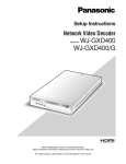
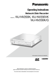
Operation flow
The operation flow of the recorder is as follows.
x
Connections
c
Startup
v
Install the HDD units
➜
z
Rack mounting
➜
➜
➜
n
Network settings of a PC
m
Formatting of the
hard disk drives
,
Network settings
of the camera
.
Setup
➜
b
Network settings
of the recorder
➜
➜
➜
➜
⁄0
Install the recorder in the rack. (Refer to the installation guide.)
Go to step 2 when not installing it in the rack.
Connect the recorder to each device. (Refer to the installation
guide.)
Turn on the power of the recorder. (Refer to the installation guide.)
When using extension units, turn the power of all the extension
units before turning on the power of the recorder.
Install hard disk drives in the recorder. (Refer to the installation
guide.)
When unformatted hard disk drives are installed, they will automatically be formatted.
According to your needs, determine the operational mode.
Operate the buttons on the front panel of the recorder to configure
the network settings of the recorder. (Page 11)
Change the TCP/IP setting of the PC to conform to the settings of
the recorder. (Page 13)
Display the disk configuration menu and format the hard disk
drives. (Page 89)
Display the camera setup menu and configure the network settings of the cameras. (Page 49)
Perform the required settings on the setup menu to start operation. (Page 8)
Start operation
➜
When necessary
Replacement of the
hard disk drives
It is possible to replace the hard disk drives without turning off the
power of the recorder. (Refer to the Installation guide.)
7
Setup menu and its items
It is necessary to configure the settings on the setup menu in advance to use the recorder. The setup menu will be
displayed by clicking the [Setup] button.
Setup items
Quick
Setup
Basic
Basic
Time & date
Emergency rec.
Emergency rec.
Event
Basic
Terminal alarm
Site alarm
Command alarm
Schedule
Time table
Program
Special days
Camera
NW camera
Group
Sequence
8
Description
Reference
page
Displays the "Quick" page that contains the minimum required
settings to be configured to operate the recorder.
26
Settings for the basic operations of the recorder can be configured.
Current time and date can be set.
31
Settings relating to emergency recording such as the recording
time and recording rate can be configured.
34
Basic settings relating to the event actions can be configured.
Event actions to be taken at a terminal alarm occurrence can
be set.
Event actions to be taken at a site alarm occurrence can be
set.
Event actions to be taken at a command alarm occurrence can
be set.
39
40
Create timetables for each day of the week, and assign a program to each timetable.
Up to 8 recording programs can be created. Settings relating
to recordings such as the recording rate for each camera
channel can be configured.
Timetables to special days aside from other days of the week
can be assigned.
47
Network settings of cameras such as the IP address and the
port number of the cameras, etc. can be configured.
The title of the camera group can be set.
Settings that required to perform the sequence display of live
images from cameras can be configured.
49
32
41
42
43
48
54
55
Setup items
Server
NTP
FTP
Mail
Proxy
Network
Basic
DDNS
SNMP
Panasonic alarm protocol
User mng.
Basic
Administrator
User
Host
User level
Description
Reference
page
Settings that are required to correct time based on the NTP
server, such as the NTP server address, can be configured.
Settings that are required to transmit images from cameras
connected to the recorder to a designated FTP server periodically can be configured.
Settings relating to the mail notification function, that sends
e-mails to addresses registered in advance at an event or error
occurrence, can be configured.
Basic network proxy settings can be configured. Determine
whether or not to use the proxy server, and configure the settings such as the server address settings, etc.
57
Network settings can be configured. Settings that are required
to connect to a network such as the IP address and gateway
address can be configured.
Setting relating to DDNS can be configured. Determine whether to enable or disable DDNS, and configure the settings of the
registered user names, etc.
Settings relating to SNMP can be configured. Configure the
settings to check the status of the recorder, etc. by connecting
the SNMP manager.
Settings that are required to send a message to addresses
registered in advance using "Panasonic alarm protocol" when
an event or a problem occurs can be configured.
63
Determine whether to enable or disable the user authentication
and the host authentication.
Information of the registered administrators such as the
administrator name, password, the default screen, etc can be
edited.
Settings relating to the user authentication such as user registration can be configured. User information can be edited or
deleted.
User name, password and operational level can be set.
Settings relating to the host authentication such as registration
of PCs (hosts) to allow to access the recorder via a network
can be configured. Host information can be edited or deleted.
Operational levels and IP addresses of PCs can be set.
Functions operable in each user level can be set.
70
58
60
62
67
68
69
71
72
74
76
9
Setup items
Maintenance
Product information
Disk information
Network information
Disk
Settings management
Config.
Disk information
Format
10
Description
Reference
page
Versions of the software, the hardware (this recorder), MAC
address, serial number, temperature inside the recorder and
software version of the connected extension unit will be displayed.
Disk partition information of the recorder will be displayed.
Information such as the recording information, operational
mode of the hard disk drives, disk capacities, available capacity of each recording area, etc. will be displayed.
Network information such as IP addresses of NW camera connected to the recorder, communication rate to network, etc.
will be displayed.
Settings relating to an action to be taken when available
capacity of the hard disk drives run out can be configured, and
data recorded on the hard disk drives can be deleted.
The settings of the recorder can be saved and the saved settings can be loaded to the recorder.
78
Information such as the recording information, operational
mode of the hard disk drives, disk capacities, available capacity of each recording area, etc. will be displayed.
Assignment of event recording area and copy area, and formatting of the hard disk drives can be performed.
87
79
82
83
85
89
Network settings
Network settings of the recorder
Configure the following settings for the ports to be used.
The following settings can be configured using the buttons on the front panel. Parameters will be displayed on the
LCD.
Setup items
DHCP
IP address
Subnet mask
Default gateway
HTTP port
Description
Determine whether or not use a DHCP server. Select "ON" to obtain an IP address,
subnet mask and default gateway from a DHCP server.
When selecting "OFF" for "DHCP", enter an IP address.
When selecting "OFF" for "DHCP", enter a subnet mask.
When selecting "OFF" for "DHCP", enter a default gateway.
Designate the HTTP port number to be used. Normally "80" is to be designated.
The default network settings of the recorder are as follows.
Setup items
DHCP
IP address
Subnet mask
Default gateway
HTTP port
Camera port
–
192.168.0.250
255.255.255.0
–
–
Client PC port
OFF
192.168.1.250
255.255.255.0
192.168.1.1
80
Maintenance port
–
192.168.2.250
255.255.255.0
–
–
Important:
• The network settings for each port (IP address, etc.) should be configured with a different subnet. Otherwise,
network communication may be failed.
Note:
• When the network settings of the PC are as follows, it is unnecessary to configure the above settings. It is possible to configure the settings and operate the recorder using a web browser after completing the connection.
IP address:
192.168.1.2 to 249, 192.168.1.251 to 254
Subnet mask:
255.255.255.0
Default gateway: 192.168.1.1
When the settings values other than above are set, it is necessary to configure the network settings of the
recorder and the PC.
• The network settings of a camera can be configured on the setup menu of the camera. Refer to the "NW camera" section on page 49 for further information.
11
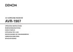
1
Confirm that the standby display is on the LCD.
When a display other than the standby display is on
the LCD, continue pressing the [ESC] button until
the standby display is displayed on the LCD.
2 Display the IP address setup display by press the
arrows button (up or down).
3 Press the [SET] button.
The "PT#1 IP ADDR" indication will be displayed.
6 Press the [SET] button while the underscore
mark (_) is displayed below the ">" indication.
Move the underscore mark below the number to be
edited.
The current selected settings item or a value will be
indicated by the underscore mark "_".
7
Enter values using the arrows button.
Move the underscore mark "_": Arrows button (left
or right)
Enter a value: Arrows button (up or down)
8 To determine the edited setting, move the underscore mark below the ">" indication by pressing
the [ESC] button.
9 To configure other setting items, shift the display
by pressing the arrows button (up or down).
4 Select the desired network port by pressing the
arrows button (left or right).
PT#1: Camera port
PT#2: Client PC port
PT#3: Maintenance port
5 Display the settings item by pressing the arrows
button (up or down).
DHCP
IP address
Subnet mask
Default gateway
HTTP port
Note:
• The settings of DHCP, default gateway and HTTP
port can be configured only for "PT#2".
12
10Repeat steps 5 - 8 to configure each setting
item.
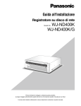
Network settings of a PC
Change the TCP/IP setting of the PC to conform to the settings of the recorder. It is necessary to set the IP address
of the PC and the client PC port of the recorder in the same subnet to access the recorder.
In these operating instructions, the settings are performed on Windows XP as examples. When using an operating
system other than Windows XP, refer to the operating instructions of the OS in use.
Example: When using the recorder with the default (IP address: 192.168.1.250), set the IP address of the PC to
"192.168.1.xxx (a number from 2 to 254 except 250)".
1 Log in to the PC as an administrator.
2 Click "Start" on the taskbar, and then click the
4
Click "Network Connections".
The "Network Connections" window will be displayed.
"Control Panel".
3 Click the "Network and Internet Connections"
icon.
The "Network and Internet Connections" window
will be displayed.
5 Double click "Local Area Connection".
The "Local Area Connection 2 Status" window will
be displayed.
13
6
Click "Properties".
The "Local Area Connection 2 Properties" window
will be displayed.
8 Click "Use the following IP address" and enter
the IP address and the subnet mask as follows;
IP address: Set in the same subnet as the recorder's.
Depending on the network configuration, it is necessary to configure the default gateway. Refer to a
system administrator for information on how to configure the setting.
9 Click the [OK] button and close the window.
7 Click "Internet Protocol (TCP/IP)", and then click
"Properties".
The "Internet Protocol (TCP/IP) Properties" window
will be displayed.
14
About the operation window
Display/Close the operation window
Display the operation window using a web browser installed on a PC.
1 Boot the PC.
2 Launch a web browser.
4 Enter the user name and password registered on
the recorder and then click the [login] button.
The top page will be displayed.
3 After the browser starts, enter the IP address set
to the recorder in the address box, and press the
enter key.
The authentication window will be displayed.
This window will not be displayed when "Off" is
selected for "User authentication" on the "Basic"
tab page of "User management". (Page 70)
Important:
• Refer to a system administrator for the set IP
address of the recorder.
• It is impossible to access the recorder from a PC
which IP address is not registered to the recorder
when "On" is selected for "Host authentication" on
the "Basic" tab page of "User management". (Page
70)
Refer to a system administrator for further information.
• Do not attach "0" before the numbers when entering
IP address.
Example:
OK: 192.168.0.50
NG: 192.168.0.050
• If a message is displayed on the information bar,
see page 102.
Important:
• Refer to a system administrator for the set user
name and password.
Refer to the "User" section on page 72 for information on how to register users.
• The default administrator name and password are
as follows
User name: ADMIN
Password: 12345
• To enhance the security, change the password for
an administrator before running the recorder.
Change the password periodically. Refer to page 72
for information on how to change the password.
• When the recorder is being operated without changing the user name and password, the pop-up window saying that it is recommended to change the
password will be displayed.
15
5 Configure the settings and perform operations
by clicking the buttons and the tabs on the operation window.
Important:
• If a message is displayed on the information bar,
see page 102.
Note:
• When the top page is displayed for the first time, the
install wizard of the ActiveX control required to display images from the camera will be displayed.
Follow the instructions of the wizard.
• When ActiveX for WJ-ND200/WJ-ND300 is
installed, remove "WebVideo ActiveX" using the
"Add or Remove Programs" control panel. After
confirming that "WebVideo ActiveX" is deleted,
install ActiveX of WJ-ND400.
• When the install wizard is displayed again even after
completing the installation of the ActiveX, reboot the
PC.
6 Close the web browser when there is no more
operation/settings configuration to be performed.
Click the [X] button at the top right of the window or
shut down the browser.
16
Major operating controls and their functions
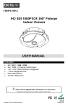
Top page
w
e
r
t
q
y
u
o
i
q [Control] button (page 18)
The operation panel will be displayed by clicking
this button, and operations such as searching for
recorded pictures on the hard disk drives and copying recorded images onto the copy area of the hard
disk drives can be performed from the displayed
operation panel. From the displayed operation
panel, it is also possible to display images by
switching the camera channels such as changing
the screen of live image display from 1-screen to
4-screen, and the sequence display. Search results
or log information will also be displayed on this
panel.
y Image display area
Recorded images and live images will be displayed.
The camera title is displayed at the upper left and
the time and date (the current time and date of the
camera's clock when displaying live images and the
time and date when images were recorded when
playing recorded images) at the upper right. Clicking
the camera title during displaying images on a
4-screen will display images from the respective
camera channel on a 1-screen.
At the default, the aspect ratio of each screen segment is 4:3. Refer to the aspect ratio setting (page
32) for changing the aspect ratio to 16:9.
w [Cam. Select] button (page 19)
The switcher functions such as switching camera
channels are operable on this page.
u Playback point operation area (page 22)
It is possible to designate a playback point or to
skip to the latest recorded image.
e [Setup] button (page 20)
The settings of the recorder can be configured on
the setup menu pages displayed by clicking this
button.
i [HDD] tab (page 22)
Playback operation and downloading a recorded
image onto a PC can be performed on this tab.
r Status display area (page 21)
The status of the recorder such as the recording
status, playback status, etc. will be displayed.
o [CAM] tab (page 24)
Camera operations such as zooming, focusing, auto
functions, etc. can be performed on this tab.
t Current time display area
The current time will be displayed.
17
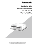
[Control] button
The following operation panel will be displayed when
the [Control] button is clicked.
e
q
w
t
r
y
u
i
q [Multiscreen select] box
Images from up to 4 cameras can be displayed
simultaneously on a multi-screen. Each time the
button is clicked, images from the 4 cameras registered as a group in advance will be displayed on a
4-screen. (Page 51)
w [Sequence] box
When this button is clicked, the camera channels
will be switched automatically and images from
them will be displayed sequentially according to the
settings configured in advance. The indicator on the
button will light (green) during sequence display.
(Page 55)
18
e [EL-zoom] box
Camera images will be displayed in the proportion
of the clicked zoom ratio button.
: 1x
: 2x
: 4x
r [Search] box
[Search] button
Use this button to search the recorded images.
Search results will be displayed in list form in the list
display area.
(Refer to the operating instructions (PDF).)
[Area select] button
Use this button to select a disk on which recorded
images are to be played/searched.(Refer to the
operating instructions (PDF).)
t [Copy] box
The "Data copy" window will be displayed by clicking this button. Copying recorded images onto the
copy area of the hard disk drive can be performed
on the "Data copy" window.
y [Log] box
Logs will be displayed in list form in the list display
area.
[Error log] button
The error logs will be in list form in the list display
area.
[Access log] button
The time and date when logged in/out of the recorder, the user name, and the IP address will be displayed. The access logs will be displayed in list form
in the list display area.
[Event log] button
The time and date of event occurrences and their
details will be displayed. The event logs will be displayed in list form in the list display area.
[Network log] button
The network logs will be displayed in list form in the
list display area.
u List display area
Number of listed data (recording events or logs)
Total number of listed data (recording events or
logs) will be displayed. When the total number of
the listed data is more than 10 000, the ">10000"
indication will be displayed.
[All list] button
Cancels filtering and lists all recording events.
[Refresh] button
Updates the list.
[Prev page] button
Displays the previous page of the list.
[Next page] button
Displays the next page of the list.
[Time & date]
Start time of recording will be displayed.
[Ch]
A camera channel used for recording will be displayed.
[Rec]
Recording mode will be displayed.
HDD (hard disk drive)
The hard disk drive number in which the corresponding recorded images are stored will be displayed.
[Info]
Additional information will be displayed.
: Audio is attached to images.
i [Zoom in] button
Enlarges live or recorded images displayed in the
image display area.
Live images and recorded images will be displayed
in the size selected for the aspect ratio setting.
Refer to page 32 for further information about the
aspect ratio setting.
Note:
• The recording event list will be displayed when the
[Refresh] button is clicked or when performing the
search or the area selection. Refer to the operating
instructions (PDF) for further information about the
search and the area selection.
• The [All list] button is unavailable during playback.
Start operation after stopping the playback.
• When using many cameras, the recording event list
may not be displayed in the recording start time
order of each camera channel.
[Cam. select] button
The following operation panel will be displayed when
the [Cam. select] button is clicked.
e
q
w
Group title
r
Camera title
q [Multiscreen select] box
Images from up to 4 cameras can be displayed
simultaneously on a multi-screen. Each time the
button is clicked, images from the 4 cameras registered as a group in advance will be displayed on a
4-screen. (Page 51)
w [Sequence] box
When this button is clicked, the camera channels
will be switched automatically and images from
them will be displayed sequentially according to the
settings configured in advance. The indicator on the
button will light (green) during sequence display.
(Page 55)
e [El-zoom] box
Camera images will be displayed in the proportion
of the clicked zoom ratio button.
: 1x
: 2x
: 4x
r [Cam. select] box
When clicking "WJ-ND400", a group title (title of a
group consisted of the 4 registered cameras) will be
displayed. Refer to page 54 for further information
about the camera group settings.
When clicking the group title, a list of the cameras
consisting of the group will be displayed. Clicking
the camera title will display images from the selected camera channel on a 1-screen in the image display area.
19
[Setup] button
The following operation panel will be displayed when
the [Setup] button is clicked.
r [Event] button
Displays the "Event" page that contains the settings
relating to the event actions to be taken at an event
occurrence for each event type (site alarm, terminal
alarm, command alarm).
t [Schedule] button
Displays the "Schedule" page that contains the settings relating to the schedule recording and the
event action.
q
w
y [Camera] button
Displays the "Camera" page that contains the network settings of cameras, and the settings relating
to the group and the sequence display.
e
r
t
u [Server] button
Displays the "Server" page that contains the settings of the NTP server, FTP server, mail server and
proxy server.
y
u
i
o
!0
i [Network] button
Displays the "Network" page that contains the network settings.
o [User mng.] button
Displays the "User mng." page that contains the
settings relating to authentication.
!1
!2
q [Quick] button
Displays the "Quick" page that contains the minimum required settings to be configured to operate
the recorder.
!1 [Config.] button
Displays the "Disk config." page that contains the
disk partition information display page, the settings
relating to formatting of the hard disk drives.
w [Basic] button
Displays the "Basic" page that contains the basic
system settings and the time & date settings.
Important:
• When any of edited settings are applied, all login
users will forcibly be logged out.
!2 [Help] button
The "Help" page will be displayed.
e [Emergency rec.] button
Displays the "Emergency rec." page that contains
the settings relating to the emergency recording.
20
!0 [Maintenance] button
Displays the "Maintenance" page that contains the
information display pages (about the recorder, disk
and network), and the settings relating to the hard
disk drives and saving/loading of the settings.
Status display area
(1)
q
(2)
w
q The status of the recorder such as the status,
playback status, etc. will be displayed.
: Indicates that live images are being displayed.
: Indicates that playback images are being displayed.
: Indicates that reverse playback images are
being displayed.
: Indicates that fast playback images are being
displayed.
: Indicates that fast reverse playback images
are being displayed.
: Indicates that a paused image is being displayed.
: Indicates that recorded images/audio are
being downloaded.
: Indicates that downloading of recorded images/audio is completed.
[Step 1] - [Step 7]: Indicates the playback speed.
(3)
e
(4)
r
: Indicates that the HDD copy area is
being selected.
: Indicates that SD memory data is being
obtained.
: Indicates that data recovery in the RAID
mode is being performed.
: Indicates that the recording events are
being filtered. Refer to the operating
instructions (PDF) for further information
about filtering of the recording event list.
w [REC] indicator
Indicates the status of recording.
: Normal playback speed (1x)
: Approx. 4x playback speed
: Approx. 8x playback speed
: Approx. 16x playback speed
: Approx. 32x playback speed
: Approx. 48x playback speed
: Approx. 96x playback speed
: Indicates that recording is being performed.
: Indicates that recording is not being performed.
e Indicates the following statuses.
: Indicates that the camera is not operable
because a user with higher priority is
currently operating the camera.
: Indicates that copying is being performed.
: Indicates that deletion of recorded images is being performed.
: Indicates that the sequence display is
being performed.
r Indicates information about events and errors.
[ALARM SUSPEND] button
: Indicates that playback of recorded
images stored in the normal recording
area or the event recording area of the
hard disk drives on the recorder is being
selected.
: Clicking this button will temporarily disable alarm actions. (Refer to the operating instructions (PDF).)
: Indicates that an alarm is being suspended.
21
[ALM] button
: Indicates an event occurrence. The alarm
action will be canceled by clicking this button. (Refer to the operating instructions
(PDF).)
Note:
• Once an emergency recording starts, it will not stop
even by clicking the [ALM] button. It will stop only
when "Continue" is selected for "Recording duration" on the "Emergency rec." page.
[ERR] button
: Indicates an error occurrence. The error
action will be canceled by clicking this button. Refer to the operating instructions (PDF)
for further information.
Playback point operation area
q
w
q Indicates the start time and the end time of
recorded images to be downloaded.
[Start]:Designate the start time from when recorded images are to be downloaded.
[End]:Designate the end time till when recorded
images are to be downloaded.
e
w [Go to date]
Designate the desired time and date from when
playback of recorded images is to start.
e [Go to last]
Click this button to skip to the latest recorded image
from the camera channel currently being displayed
and start playback.
[HDD] tab
q
22
w
e
r
t
u
i
o
!0
q [REW] button
Plays recorded images in reverse at high speed.
Playback speed of fast reverse playback will change
in the following order each time this button is
clicked: Step2 (Approx. 4x) → Step3 (Approx. 8x) →
Step4 (Approx. 16x) → Step5 (Approx. 32x) →
Step6 (Approx. 48x) → Step7 (Approx. 96x)
y
!1
!2
w [PREV RECORD] button
Skips to the previous recorded image and plays it.
e [REV PLAY] button
Plays recorded images in reverse.
r [PLAY] button
Plays recorded images.
t [NEXT RECORD] button
Skips to the next recorded image and plays it.
y [FF] button
Plays recorded images at high speed.
Playback speed of fast playback will change in the
following order each time this button is clicked:
Step2 (Approx. 4x) → Step3 (Approx. 8x) →
Step4 (Approx. 16x) → Step5 (Approx. 32x) →
Step6 (Approx. 48x) → Step7 (Approx. 96x)
u [PREV IMAGE] button
The previous frame will be displayed when this button is clicked during playback/pause.
i [PAUSE] button
Playback will be paused when this button is clicked
during playback.
Playback will resume when this button is clicked
during pause.
o [STOP] button
Stops playback and displays live images.
!0 [NEXT IMAGE] button
The next frame will be displayed when this button is
clicked during playback/pause.
!1 [Download (TO PC)] box
Downloads the recorded images currently being
played to a PC.
[Download] button: Downloads recorded images
and audio.
[Viewer] button: Downloads the viewer software
that can play downloaded images.
Important:
• To display the recording button and the recording
stop button, hold down the Up button until they
appear.
Note:
• When playing MPEG-4 images, results from operating the some buttons will be as follows.
[Go to date] button: Playback sometimes may start
from a point several seconds after the designated time and date.
[REV PLAY] button: Some frames of recorded
images will not be displayed. Reverse playback
will be performed with the set refresh interval of
the camera.
[PLAY] button (during playback): When the [PLAY]
button is clicked during playback, images will be
skipped for several seconds.
[PREV IMAGE] button: Some frames of recorded
images will not be displayed. Reverse frame by
frame playback will be performed with the set
refresh interval of the camera.
[FF]/[REW] button: Some frames of recorded images will not be displayed. Fast playback/fast
reverse playback will be performed with the set
refresh interval of the camera.
[Download] button (during playback): Download
may start from a point several seconds before
the designated start time and end at a point several seconds after the designated end time.
!2 [Rec] box
The recording button and the recording stop button
will be displayed when the Up button is clicked.
The recording button and the recording stop button
will be hidden when the Down button is clicked.
Recording button: Starts manual recording.
ecording stop button: Stops manual recordR
ing.
23
[CAM] tab
When displaying live images from a camera with the panning/tilting function, it is possible to operate the camera
(pan/tilt, zoom, focus, brightness, preset position and auto function). It may be impossible to operate the camera or
some functions may be inoperable depending on the model of the camera.
q
e
w
q [Zoom] box
Zooming can be adjusted by clicking the [-] button
or the [+] button. Click the [x1] button to reset zoom.
w [Focus] box
Focusing can be adjusted by clicking the [Near] button or the [Far] button.
The auto focus function can be performed by clicking the [Auto] button.
e [Auto mode] box
Activate the designated auto function of the camera. Select the auto mode function (auto track, auto
pan, preset sequence, sort, or patrol) of the camera
by clicking the [V] button, and then click the [Start]
button. Click the [Stop] button to stop the auto
mode function.
r Control pad/buttons
Clicking the buttons around the control pad can
move (pan/ tilt) a camera in the clicked direction.
Clicking inside the control pad also can adjust the
vertical/ horizontal position (pan/tilt) of the displayed
image. Panning/ tilting speed will be faster if a
clicked point gets farther from the center point of
the control pad.
24
r
t
y
t [Brightness] box
The brightness can be adjusted by clicking the [-]
(darker) button or the [+] (brighter) button.
It is possible to reset the set brightness by clicking
the [Reset] button.
y [Preset] box
[Go] button
Move the camera to the preset position registered in
advance. Select a preset position number (Home, 1
- 256) by clicking the [V] button, and then click the
[Go] button.
It is necessary to register preset positions in
advance to move the camera to the preset positions.
[Set] button
Register the camera position as a preset position by
designating the desired preset position number.
Select a preset position number (1 - 256) by clicking
the [V] button after moving the camera to a position
to be registered as a preset position, and then click
the [Set] button. (It is impossible to register the position as "Home".)
Basic operation
Access the recorder and display the top page of
the operation window.
1
2
Click the [Setup] button.
The setup menu buttons will be displayed.
4
Click the desired tab on the setup menu page.
The setup menu page of the clicked tab will be displayed.
5 Configure each setting item.
6 Click the [Set] button after completing each set-
ting item.
The configured settings will be applied.
When displaying other setup menu page without
clicking the [Set] button, the edited settings will not
be applied.
3
Click the desired setup menu button.
The setup menu page respective to the clicked
setup menu button will be displayed.
Important:
• When any of edited settings are applied, all login
users will forcibly be logged out.
• When any setting relating to the user management
is edited and applied, all login users will forcibly be
logged out.
• It may be impossible to record images for around 4
seconds just after clicking the [Set] button to apply
the edited settings.
• Only a single user can operate the setup menu at a
time. It is impossible to open the setup menu when
another user is operating it.
• When the web browser is closed in the process of
accessing the setup menu to open, it will become
impossible to access the setup menu for around 90
seconds. When any of the setup menu buttons is
clicked, the message window saying that the other
user is currently operating the setup menu.
25
Quick settings
Configure the minimum settings required to operate the recorder such as the language setting, time & date, network settings, camera registration, etc.
Setup
Language/Time & date
Select the display language and set the current time and date.
Click the [Quick] button.
Configure each setting item.
The "Quick" page will be displayed.
Refer to "Setup items" mentioned below.
1
2
3 Click the [Set] button just below the "Time &
date" setting.
Important:
• A black screen may be displayed and recording may
not be performed for around 4 seconds just after
the current time and date is changed by editing the
time & date setting or shifting to/from summertime.
Note:
• When no camera is registered, the "Quick" page will
be displayed automatically.
• There are 4 sections according to the related settings as follows; "Language/Time & date", "Network
settings", "Network camera registration setup" and
"Program setup". After editing the settings, click the
[Set] button in each section to apply the edited settings.
Setup items
■Language
Select the display language of the web browser from
the following.
Contact your dealer for further information about the
customized language (Custom).
Japanese/English (default)/Français/Español/Deutsch/
Italiano/Russian/Chinese/Custom
■Time & date
Adjust the current time and date.
Select numbers for year, month, day, hour and minute,
and click the [Set] button.
08 - 34 (year)/1 -12 (month)/1 - 31 (day)/0 - 23 (hour)/
0 - 59 (minute)
26
Network settings
Configure the network settings of the recorder.
1
Click the [Quick] button.
The "Quick" page will be displayed.
2
Configure each setting item.
Refer to "Setup items" mentioned below.
Setup items
■Network setup - Camera port/Client PC port
Configure the following setting items for each port.
[DHCP]
Select "On" or "Off" to determine whether or not to use
the DHCP server.
Select "On" to obtain an IP address, a subnet mask
and a gateway address from the DHCP server. Select
"Off" when entering values manually.
On: Uses the DHCP server.
Off (default): Does not use the DHCP server.
[IP address] *1
When "Off" is selected for "DHCP", enter an IP
address.
[Subnet mask] *1
Enter a subnet mask according to the network configuration when "Off" is selected for "DHCP".
[Default gateway] *1
Enter the address of the default gateway according to
the network configuration when "Off" is selected for
"DHCP".
[Line speed]
The following are available for "Line speed".
Auto (default)/1000M-Full/100M-Full/100M-Half/
10M-Full/10M-Half
3 Click the [Set] button in the "Network setup"
section.
When the IP address of the client PC port is
changed, the following window will be displayed.
Click the [OK] button to apply the setting.
Note:
• When the IP address of the client PC port is
changed, all login users will forcibly be logged out.
It is necessary for users to access the changed IP
address to reconnect to the recorder.
• When the "Line speed" setting is changed and the
[Set] button is clicked, the recorder will reboot.
■Network setup - Maintenance port
[IP address] *1
Enter an IP address.
[Subnet mask] *1
Enter a subnet mask.
*1 Refer to page 11 about the default setting.
Important:
• The network settings for each port (IP address, etc.)
should be configured with a different subnet.
• When "On" is selected for "DHCP" and any frame
rate other than "Off" is select for "SD memory rec.",
a request for writing data onto the SD memory card
demanded at the startup of the recorder may fail.
This error may occur when the response from the
DHCP server is slow.
However, a request for writing data onto the SD
memory card will be accepted once the addresses
have been obtained from the DHCP server.
27
Camera registration
Register cameras in the recorder. Up to 64 cameras can be registered.
• Automatic IP address assignment by selecting
Click the [Quick] button.
"Register the IP address automatically given by this
The "Quick" page will be displayed.
unit to a detected camera" is available only when
"Off" is selected for the "DHCP" setting of the
recorder.
• Set "255.255.255.0" for "Subnet mask" of the network port when selecting "Register the IP address
automatically given by this unit to a detected camera".
• When automatically assigning an IP address, the
gateway shall belong to the same segment of the
port selected in step 2. Otherwise, IP address may
not automatically be assigned to a camera depending on the model.
• The HTTP port number of the camera will be "80"
automatically when the IP address of the camera is
registered. The values of the subnet mask and the
default gateway of the camera will be set to the
Select a port to which cameras are connected to
same values as the recorder's.
detect them.
Camera port/Client PC port
Click the [Registration] button.
The confirmation window will be displayed.
Determine how to assign and register an IP
address of the detected camera.
[Register the IP address automatically given by this
unit to a detected camera]
[Register the IP address set with a detected camera]
1
2
4
3
Note:
• When selecting "Register the IP address automatically given by this unit to a detected camera", an
available IP address (not used for any device) will be
assigned to the detected camera. However, the IP
address used for other device may be assigned
depending on the network environment (such when
the firewall function of Windows XP is used). If the
IP address used for other device is assigned to the
camera, check the IP addresses and assign an IP
address to the camera manually.
• When selecting "Register the IP address automatically given by this unit to a detected camera" for a
camera of which the "DHCP" setting is "On", the
"DHCP" setting of the camera will be set to "Off"
automatically and an IP address will be assigned
newly.
28
5
Click the [OK] button.
Detection of cameras and registration of the detected cameras will start.
The "Setting" window will be displayed in the process of the registration.
The "Camera Registration Result" window will be
displayed after the registration is complete.
6
Check the registration result.
• Up to 64 cameras can be registered.
• Only the newly registered cameras will be displayed
on the "Camera Registration Result" window. Even
when 65 or more cameras are on the network, only
64 cameras will be displayed.
• When the same IP address is assigned to multiple
cameras, the IP address used for multiple cameras
and the MAC addresses of the cameras will be displayed in red. Make sure that the IP addresses of
the cameras are all different and the same address
is not used for two cameras or more.
7 Click the [OK] button.
Registration of the cameras will complete.
Important:
• When the [Registration] button is clicked after
selecting "Register the IP address automatically
given by this unit to a detected camera", IP
addresses will be assigned to all the detected cameras. Start registration of the camera after confirming that no problem will occur when some cameras
are already in operation.
Note:
• When the desired camera is not detected or when
the settings of a camera are required to be changed,
configure the settings on the "NW camera" page
(page 49).
• When the camera registration is complete, all login
users will forcibly be logged out.
• All recordings will stop in the process of the camera
registration.
• Camera auto-registration will not work with cameras
in the different subnet via a router.
• To enhance the security, a camera can be detected
for only 20 minutes after turning on the power of the
camera when the default IP address is changed
depending on the model of the camera. Refer to the
operating instructions of the camera in use for further information.
• The compression method of the registered camera
will be set to "JPEG" or "M-JPEG" automatically.
Setup items
■Port setup
Select a port to which the camera to be registered is
connected.
Camera port (default)/Client PC port
■Camera auto-registration
Determine how to assign IP addresses to the detected
cameras.
"Register the IP address automatically given by this unit
to a detected camera" (default)
"Register the IP address set with a detected camera"
Note:
• When "On" is selected for "DHCP" of "Port setup"
of the recorder, it is impossible to assign IP
addresses to the detected cameras.
29
Program setup
Select a program that determines basic operation of the recorder such as the live image transmission rate, recording rate, etc.
Click the [Quick] button.
Configure each setting item.
The "Quick" page will be displayed.
Refer to "Setup items" mentioned below.
1
2
3
Click the [Set] button.
Setup items
■Program setup
Select a program.
Program 1 (default) - Program 8
Click the [Display] button to check the detailed settings
of the selected program.
Refer to the "Program" section on page 43 for information on how to set programs.
30
Note:
• When the camera registration is performed on the
"Quick" page, the live image transmission rate and
the recording rate (manual recording) of "Program
1" - "Program 8" will be set to "1 ips".
Basic settings
Configure the settings required for the basic operations of the recorder.
Basic
Configure the basic system settings.
Click the [Basic] button.
1
2 Click the [Basic] tab.
The "Quick" page will be displayed.
3
Configure each setting item.
Refer to "Setup items" mentioned below.
4
Click the [Set] button.
Setup items
■Recording
Select "On" or "Off" to determine enable or disable the
recording function of the recorder.
When "Off" is selected, recording will not be performed.
Select "On" normally, except when it is necessary to
stop recording forcibly.
■LCD setup lock
Select "On" or "Off" to determine whether or not to lock
the buttons on the front panel (key lock).
When "On" is selected, the buttons will be locked again
when no operation using the buttons is performed for
around 1 minute even releasing the key lock by entering
the password from the front panel.
■Password
Enter the password to release the key lock.
Enter up to 5 numeric characters.
■Language
Select the display language of the web browser from
the following.
Contact your dealer for further information about the
customized language (Custom).
Japanese/English (default)/Français/Español/Deutsch/
Italiano/Russian/Chinese/Custom
■Go to last before
Select a time to be skipped to when the [Go to last]
button is clicked during playback from the following.
5s/10s/30s (default)/1min/5min (before the latest
recorded image)
■Buzzer
Determine whether or not to sound the buzzer at an
error occurrence.
Off: The buzzer will not sound at an error occurrence.
2s (default)/5s/10s/20s/30s/1min: The buzzer will
continue sounding for the selected duration.
Ext: The buzzer will continue sounding until the
[BUZZER STOP] button on the front panel is
pressed or until the [ERR] button on the operation
window is clicked.
31
■Error output duration
Set the duration of the error output that is issued to an
external device at an error occurrence. Refer to the
installation guide for further information about the error
output.
Off: The error output will not be output at an error
occurrence.
2s (default)/5s/10s/20s/30s/1min: The duration of
error output will be output for the selected duration.
Ext.: The error output will continue until the [ERR] button on the operation window is clicked.
■Safe shutdown time
Select a wait time for the shutdown process to start
after an outage detection signal is provided to the
recorder.
10s (default)/20s/30s/1min/2min/3min/4min/5min
■Aspect ratio
Set the aspect ratio to display the images in the web
browser window.
4:3 (default)/16:9
Time & date
Configure the time and date settings of the recorder.
Click the [Basic] button.
1
2 Click the [Time & date] tab.
The "Time & date" page will be displayed.
3
Configure each setting item.
Refer to "Setup items" mentioned below.
4
Click the [Set] button.
Setup items
■Date display format
Select a date display format from the following.
(Ex. April 1st., 2009)
YY.MM.DD: 09.04.01
MMM.DD.YY: APR.01.09
DD.MMM.YY: 01.APR.09
Default: MMM.DD.YY (NTSC), DD.MMM.YY (PAL)
32
■Time display format
Select a time display format from the following.
(Ex. 3 o'clock in the afternoon)
12h: 3:00PM
24h: 15:00
Default: 12h (NTSC), 24h (PAL)
■Time & date
Set the current time and date.
Select numbers for year, month, day, hour and minute,
and click the [Set] button. The selected time and date
will start from the moment when the [Set] button is
clicked.
09 - 34 (year)/1 - 12 (month)/1 - 31 (day)/0 - 23 (hour)/
0 - 59 (minute)
■Time zone
Set the time zone of the camera.
GMT–12:00 - GMT+13:00
Default: GMT–5:00 (NTSC), GMT+0:00 (PAL)
■Auto adjustment time
Select a method of auto clock adjustment from the following.
Off (default): Does not adjust clock automatically.
Slave: Receives a signal from the master unit and
adjusts the clock of the recorder.
Master: Supplies a signal from the ALARM/CONTROL
connector on the rear panel to the connected devices and the devices will adjust their clocks with reference to the clock of the recorder.
■Summer time(daylight saving) table
Set the start (In)/end (Out) time and date of summer
time.
When the [Setup >>] button is clicked, the following
window will be displayed.
■Activation time
Set the time to start the auto clock adjustment.
When "Master" is selected for "Auto adjustment time",
set the time for a signal to supply from the ALARM/
CONTROL connector (time adjustment I/O, pin no. 20)
at the rear of the recorder.
When "Slave" is selected, set the time for the recorder
to receive a signal from the master unit and adjust the
clock.
■Summer time(daylight saving)
Determine how to shift to/from the summer time from
the following. During summer time, the time will be displayed with an asterisk (*).
Out (default): Summer time will not be applied.
Auto: Applies summer time in accordance with the setting of summer time.
Set the start time and date and the end time and date
of summer time. Select the last 2 digits of the year.
Up to 10 settings can be set.
Click the [Set] button after completing the settings, and
close the window by clicking the [X] button at the top
right of the window.
Important:
• A black screen may be displayed and recording may
not be performed for around 4 seconds just after
configuring/editing the following settings.
• When the current time and date setting is configured/edited
• When the summer time is applied to the current
time
• When "Slave" is selected for "Auto adjustment
time" and the clock of the recorder is adjusted
(However, when an emergency recording or an
event recording is being performed, the clock
will not be adjusted.)
33
Emergency recording
Configure the settings relating to emergency recording such as recording duration, recording rate, etc. Refer to the
installation guide for further information about the emergency recording.
Click the [Emergency rec.] button.
Configure each setting item.
The "Emergency rec." page will be displayed.
Refer to "Setup items" mentioned below.
To display the setting page of the camera whose
camera number is not on the current page, click the
desired camera channel number range displayed
above the [Set] button.
When displaying other setting page of the camera
by clicking the camera channel number range above
the [Set] button, the settings edited on the currently
displayed setting page will be saved and applied.
1
2
3 Click the [Set] button.
Important:
• It may be impossible to record images for around 4
seconds just after an emergency recording ended.
Setup items
■Recording duration
Set the recording duration of the emergency recording.
The following are available for the recording duration.
2s/5s/10s (default)/20s/30s/1min/3min/5min/10min/
30min/Manual/Continue
Manual: Recording will be performed as long as the
emergency recording input signal is being supplied.
Recording will be continued at least for 8 seconds.
Continue: Recording will not stop until the [ALM] button is clicked.
■Model
The model of the network camera will be displayed.
■Compression
The compression method of the selected camera will
be displayed.
Refer to the "Check/change the settings of the camera
manually" section (page 51) for further information on
how to configure the compression method setting of
the camera.
[Measurement]
■Max. network speed (Mbps)
The maximum network speed of the network currently
accessing will be displayed when the [Measurement]
button is clicked.
34
■Max. bit rate (ips)
The maximum recording rate of the network currently
accessing will be displayed when the [Measurement]
button is clicked.
Note:
• When the recording rate is displayed in red, it may
be impossible to transmit live images and record
images at the current recording rate.
Recorder setup
■Recording rate
Set the recording rate of the emergency recording for
each camera channel. The following are available for
the recording rate.
Off (default)/1ips/2ips/3ips/5ips/10ips/15ips/All/I-Frame
Note:
• The available recording rates differ depending on
the compression method of the camera. Refer to the
"Check/change the settings of the camera manually" section (page 51) for further information on how
to configure the compression method setting of the
camera.
■Audio rec.
Select "On" or "Off" to determine whether or not to
record audio together with images.
Audio can be recorded together with images. It is
impossible to record audio without images.
Audio recording is available only when using cameras
that support the audio recording function.
Refer to the "readme.txt" on the provided CD-ROM for
information about the camera models that support the
audio recording function.
Camera setup
■SD memory rec.
Determine whether or not save images on the SD memory card when the network communication is disconnected during emergency recording.
The following recording rates are available for "SD
memory rec.".
Off (default)/0.1ips/0.5ips/1ips
Refer to page 36 for further information about the SD
memory recording.
Note:
• The recording rate setting for "SD memory rec." is
available only for cameras that support the SD
memory recording function and their image compression method is set to "M-JPEG".
• Do not set the recording rate of the SD memory
recording for the same camera with multiple recorders.
• It is impossible to simultaneously perform audio
recording and the SD memory recording.
• When the "SD memory rec." setting on the
"Emergency rec." page is set to other than "Off" for
a camera channel, the "Audio rec." setting on the
"Emergency rec." page for this camera channel will
be set to "Off" automatically.
Important:
• If receiving a signal input that triggers an emergency
recording when the communication between the
recorder and the camera is not established, the SD
memory recording will not be performed (since the
camera cannot recognize the trigger of the emergency recording).
• When selecting "On" for "Audio rec.", make sure
that the settings of the camera are configured to
transmit audio. Set also the audio bit rate of the
camera to "32kbps".
• When the audio bit rate of the camera is changed
during operation, set the "Audio rec." setting of the
recorder to "Off" once, and then set to "On" again.
• Audio may be interrupted depending on the audio
transmission interval setting of the camera. Change
the settings of the camera according to the network
environment.
• Audio may be interrupted depending on the recording rate setting. Change the recording rate setting
according to the network environment.
• To record audio, select "Mic input" or "Interactive
(Full-duplex)" for the "Audio transmission/reception"
setting of the camera."Interactive(Full-duplex)" may
not be available depending on the model or version
of the camera. Refer to the operating instructions of
the camera in use for further information.
• Audio will be recorded regardless of the screen pattern (1-screen, multi-screen).
[Measurement] button
It is possible to check if the set recording rate and
transmission rate are appropriate for the network in use
by clicking the [Measurement] button. When the recording rate or the transmission rate is displayed in red, it
may be impossible to transmit live images or record
images at the current rate. It will take around 90 seconds to check.
• When the result value is beyond the maximum network speed of the recorder, the following may occur
due to the heavy network traffic:
• Some images to be recorded may not be done.
• Some live images to be displayed may not be
done.
• Some alarms to be issued may not be done.
• Operational response may become slow.
• The recorder may reboot.
• Even when the result value is below the network
speed (128 Mbps as indication), the above problems may occur depending on number of the connected cameras and PCs.
Important:
• Network traffic changes every moment. In any circumstances, the result value should be less than the
maximum network speed of the recorder.
• In the process of the measurement, recording, playback, live image display and copying will stop.
35
Note:
• Other users currently accessing the recorder will
forcibly be logged out. They need to log in to the
recorder again after the measurement.
• The result value is the reference value. Depending
on the network traffic, different result value may be
displayed even when the [Measurement] button is
clicked without changing any setting. Depending on
the network traffic or other causes, the following
may occur.
• Live images are not transmitted as configured
• Images are not recorded as configured
• Response of the web browser becomes slow
• The web browser is disconnected.
• Recording cannot be performed
We make no guarantee for any damages incurred by
recording malfunction or error occurrence regardless of what the cause may be.
SD memory rec.
Function featured in some Panasonic's cameras that
saves images on the SD memory card on the camera
when communication with the camera failed in the period set for the schedule recording of the recorder.
Recording rate setting
The SD memory recording is available only when the
camera has this function and "M-JPEG" is selected for
compression type of the "Model/Compression" setting
on the setup menu of the recorder.
The recording rate of the SD memory recording can be
set for each camera channel. (Page 43)
The start time of the SD memory recording varies
depending on the set recording rate.
The recording rate for "SD memory rec." should be less
than the recording rate set for the emergency recording.
Note:
• When setting the recording rate of the SD memory
recording, make sure that "Use" is selected for the
"SD memory card" setting of the camera. When
"Not use" is selected for the "SD memory card" setting of the camera or when no SD memory card is
inserted in the SD memory card slot of the camera
(including imperfect insertion), the error message
will be displayed several times a day and images
may not be recorded for around 20 seconds during
the error message display.
36
Obtain image recorded on the SD memory card
It is possible to obtain images recorded on the SD
memory card of the camera and save them on the hard
disk drive of the recorder.
It is also possible to check if images are currently being
obtained or not in the "Status display".
Images on the SD memory card will be obtained at the
following time.
At a quarter past the hour (0:15, 1:15 … 23:15)
Important:
• When the communication between the camera and
the recorder is disconnected during an emergency
recording, images will be saved on the SD memory
card of the camera at the set recording rate.
• If receiving an alarm signal that triggers an emergency recording or getting to the start time of the
schedule recording when the communication
between the recorder and the camera is not established, the SD memory recording will not be performed.
• Do not set the recording rate of the SD memory
recording for the same camera with multiple recorders.
• The recording time of the obtained recorded images
(SD memory data) will be displayed based on the
clock of the camera. It is recommended to synchronize the time and date of the cameras and the
recorder using the NTP server, etc. When the time
and date of the cameras and the recorder are no
synchronized, the SD memory recording may sometimes fail.
• When performing the emergency recording after
changing the recording conditions of multiple cameras, start of recording may be delayed up to 6 seconds (when performing recording images from 64
cameras simultaneously).
Note:
• Depending on the gap time between the schedules
or on the total data size of the SD memory data to
be obtained, it may be impossible to obtain all
images to be obtained at one time.
• In the following cases, images will not be obtained.
During playback, HTTP download, emergency
recording, and external recording.
• The SD memory data obtainment will be canceled
when any of the following occurs in the process of
the obtainment.
Login/Emergency recording/External recording/
Daylight saving time shift
• Some images failed to obtain can be obtained at the
next obtainment.
37
Event
Configure the settings of event recording that is to be performed at an event occurrence. Event recording includes
the pre-event recording (records images before an event occurs) and post-event recording (records images after an
event occurs).
Site alarm: When receiving a Panasonic alarm protocol
How the event action is taken
from a network camera, it will be regarded as a site
About events
alarm.
In this product, "event" is defined as phenomenon
which triggers a specific action (event action) in the
recorder.
This product regards reception of a terminal alarm, a
command alarm, and a site alarm as an "event".
For example, when the recorder receives a site alarm
issued by a camera, the recorder regards it as an event
occurrence.
About the event action
When an event occurs, the recorder will take a specified event action.
The following actions will be taken as the event actions
according to the settings.
• Record images/audio
• Record logs
• Notify of an event occurrence (by mail, LED, buzzer,
image transmission to a FTP server, etc.)
Notifications of an event occurrence are described
as "alarm action" in these operating instructions.
Events
(Terminal alarms, site alarms,
and command alarms)
Event action
-Event recording
-Log
Alarm action
-Mail notification
-LED
-Buzzer
-FTP transmission
Image of event/alarm action
38
The recorder will take an event action when the following event occurs.
Terminal alarm: When a signal from an external alarm
device such as a door sensor is supplied to the
alarm input terminal (ALARM connector on the rear
of the recorder), it will be regarded as a terminal
alarm.
Command alarm: When receiving a command from a
PC via a network, it will be regarded as a command
alarm.
The following are the event actions and their
descriptions.
• Start recording.
Recording will start according to the settings configured on the setup menu such as the recording rate,
the recording duration, etc. Images recorded before
an event occurrence can be associated with images
recorded by the corresponding event recording so
that images recorded at the event occurrence can
be played as if the recording started before the
event occurrence. (Pre-event recording) Refer to the
"Program" section on page 43 for information on
how to set recording rate.
• Display the event notification window
A pop-up window that notifies of an event occurrence will be displayed.
• The alarm indicator on the front panel will start
blinking.
• Sounds the buzzer
The buzzer will start sounding for the duration set in
advance. (Page 39)
• Move a camera to the preset position
The camera registered in advance will move to the
preset position according to the settings. Refer to
the operating instructions (PDF) for further information.
• Notifies of an event occurrence by sending e-mails
A mail that notifies of the event occurrence with the
time and date of the event occurrence will be sent.
(Alarm mail)It is possible to attach an image to the
alarm mail. (Alarm image)Up to 4 destination
addresses of the alarm mail can be registered. Refer
to the "Mail" section on page 60 for information
about the settings.
• Output signals from the ALARM/CONTROL connector on the rear of the recorder (Alarm output)
When an event occurs, a signal will be output from
the ALARM/ CONTROL connector on the rear of the
recorder to sound an external alarm buzzer, etc. The
output duration can be configured on the setup
menu. (Page 39)
• Record a log
A log that contains the event type and the time and
date of the event occurrence will be recorded.
(Event log)
• Send recorded images to an FTP server at an event
occurrence
When an event occurs, recorded images will be
continued transmitting to an FTP server automatically for the set duration from the time when the
event occurred. Refer to the "Time table" section on
page 47 and the "FTP" section (page 58) for information about the settings.
• Notify a PC of an event or an error occurrence using
the Panasonic alarm protocol
When an event or an error occurs, information about
the event/ error will automatically be notified to the
registered PC according to the "Panasonic alarm
protocol" setting. To receive a notification and display the contents of it, it is necessary to install the
optional dedicated software*.
* Refer to the "readme.txt" on the provided CD-ROM
about the dedicated software.
Basic
Set the alarm output duration and the buzzer sounding duration starting at an event occurrence (site alarm, terminal
alarm and command alarm).
Click the [Event] button.
Configure each setting item.
Refer to "Setup items" mentioned below.
1
2
Click the [Basic] tab.
The "Basic" page of "Event" will be displayed.
3
4
Click the [Set] button.
Setup items
■Alarm output
Select the alarm output duration.
The following are available for alarm output duration.
Off/2s (default)/5s/10s/20s/30s/1min/Ext/Rec
Off: No alarm output will be supplied.
Ext.: The alarm output will continue until the [ALM] button is clicked.
Rec.: The alarm output will be supplied during event
recording is being performed.
■Buzzer duration
Select the buzzer duration at an event occurrence. The
following are available for buzzer sounding duration.
Off/2s (default)/5s/10s/20s/30s/1min/Ext/Rec
Off: The buzzer will not sound.
Ext.: The buzzer will continue sounding until the [ALM]
button is clicked.
Rec.: The buzzer will sound only during the event
recording is being performed.
39
Terminal alarm
Configure the settings relating to event actions to be taken at a terminal alarm occurrence.
Refer to the operating instructions (PDF) for information on how to register the preset positions of cameras.
1 Click the [Event] button.
2
Click the [Terminal alarm] tab.
The "Terminal alarm" page will be displayed.
3
Configure each setting item.
Refer to "Setup items" mentioned below.
To display the setting page of the terminal whose
number is not on the current page, click the desired
terminal number range displayed above the [Set]
button.
When displaying other setting page of the terminal
by clicking the terminal number range above the
[Set] button, the settings edited on the currently displayed setting page will be saved and applied.
4
Click the [Set] button.
Setup items
■Rec. cam.
Select a camera channel (Cam.1 - Cam.64, "--") used
for recording. When no camera channel is selected
("--"), recording will not be performed.
■Preset position
Select a preset position (blank, 1-256) to which the
camera will move upon reception of a terminal alarm for
each terminal.
When no position is entered (blank), the camera does
not move to any preset position.
Default: blank
40
■Output terminal
Select "On" or "Off" to determine whether or not to output an alarm signal at an event occurrence.
Default: On
Site alarm
Configure the settings relating to event actions to be taken at a site alarm occurrence.
Click the [Event] button.
Configure each setting item.
Refer to "Setup items" mentioned below.
To display the setting page of the camera whose
Click the [Site alarm] tab.
camera number is not on the current page, click the
The "Site alarm" page will be displayed.
desired camera channel number range displayed
above the [Set] button.
When displaying other setting page of the camera
by clicking the camera channel number range above
the [Set] button, the settings edited on the currently
displayed setting page will be saved and applied.
1
3
2
4
Click the [Set] button.
Setup items
■Site alarm
Select "On" or "Off" whether to validate or invalidate
the site alarm.
On: Validates the site alarm.
Off: Invalidates the site alarm.
Default: Off
■Port number(from camera to ND400)
Designate the port number to be used for receiving the
site alarm.
Default: 1818
■Site alarm setup
[Rec. cam.]
Select a camera channel (Cam.1 - Cam.64, "--") used
for recording. When no camera channel is selected
("--"), recording will not be performed.
[Preset position]
Select a preset position (blank, 1-256) to which the
camera will move upon a reception of a site alarm.
When no position is entered (blank), the camera does
not move to any preset position.
Default: blank
[Output terminal]
Select "On" or "Off" to determine whether or not to output an alarm signal at an event occurrence.
Default: On
41
Command alarm
Configure the settings relating to event actions to be taken at a command alarm occurrence.
Click the [Event] button.
Configure each setting item.
Refer to "Setup items" mentioned below.
To display the setting page of the command alarm
Click the [Command alarm] tab.
whose command number is not on the current
The "Command alarm" page will be displayed.
page, click the desired command number range dis
played above the [Set] button.
When displaying other setting page of the command
by clicking the command number range above the
[Set] button, the settings edited on the currently displayed setting page will be saved and applied.
1
3
2
4
Click the [Set] button.
Setup items
■Rec. cam.
Select a camera channel (Cam.1 - Cam.64, "--") used
for recording. When no camera channel is selected
("--"), recording will not be performed.
■Preset position
Enter a preset position (blank, 1-256) to which the camera will move at an alarm occurrence.
When no position is entered (blank), the camera does
not move to any preset position.
Default: blank
42
■Output terminal
Select "On" or "Off" to determine whether or not to output an alarm signal at an event occurrence.
Default: On
Schedule recording
Configure the settings of the schedule recording by designating a day of the week and time.
Program
Set the settings of programs such as the live image transmission rate and the recording rate.
Up to 8 programs can be created.
Click the [Schedule] button.
Click the [Setup>>] button of the program to be
created.
The "Program setup" page of the selected program
will be displayed.
1
2
Click the [Program] tab.
The "Program" page of "Schedule" will be displayed.
3
Description about the button on the "Program
setup" page
[Copy] button: When it is necessary to copy the
settings of the other program, select the desired
program (source of the settings) and click the
[Copy] button.
The copied settings will be applied to the currently displayed program setup page.
[Measurement] button: It is possible to check if the
set recording rate and transmission rate are
appropriate for the network in use by clicking
this button. (Page 46)
4
Configure each setting item.
Refer to the following for further information about
the settings for each item.
To display the setting page of the command whose
command number is not on the current page, click
the desired command number range displayed
above the [Set] button.
When displaying other setting page of the camera
by clicking the camera channel number range above
the [Set] button, the settings edited on the currently
displayed setting page will be saved and applied.
43
5 Click the [Set] button after completing the set-
tings, and close the window by clicking the [X]
button at the top right of the window.
Important:
• Only the currently displayed page (the selected program) can be copied.
Setup items
■Model
The model of the network camera will be displayed.
■Compression
The compression method of the selected camera will
be displayed.
Refer to the "Check/change the settings of the camera
manually" section (page 51) for further information on
how to configure the compression method setting of
the camera.
[Measurement]
■Max. network speed (Mbps)
The maximum network speed of the network currently
accessing will be displayed when the [Measurement]
button is clicked.
■Max. bit rate (ips)
The maximum recording rate of the network currently
accessing will be displayed when the [Measurement]
button is clicked.
Recorder setup
■Live video
• Rate
Select the live image transmission rate from the following.
Off*1/1ips*2/2ips/3ips/5ips/10ips/15ips/All*3/I-Frame
The available live image transmission rates vary
depending on the compression method of the camera. Refer to the "Check/change the settings of the
camera manually" section (page 51) for further information on how to configure the compression method setting of the camera.
• Audio
Determine whether or not to transmit audio together
with live images.
Off*1*2*3/On
Note:
• Audio can be transmitted together with images. It is
impossible to transmit audio without live images.
44
• Audio transmission is available only when using
cameras that support the audio transmission function.
■Manual rec.
Set the recording rate of manual recording. The following are available for manual recording.
Off*1/0.1ips/0.2ips/0.3ips/0.5ips/1ips*2/2ips/3ips/5ips/
10ips/15ips/All/I-Frame*3
The available recording rates vary depending on the
compression method of the camera.
■Schedule rec.
Select the recording rate of schedule recording from the
following.
Off*1*2*3/0.1ips/0.2ips/0.3ips/0.5ips/1ips/2ips/3ips/5ips/
10ips/15ips/All/I-frame
The available recording rates vary depending on the
compression method of the camera.
■Event rec. - Pre-event
• Rate
Select the recording rate of the pre-event recording
from the following.
Off*1*2*3/1ips/2ips/3ips/5ips/10ips/15ips/All/I-Frame
The available recording rates vary depending on the
compression method of the camera. Refer to the
"Check/change the settings of the camera manually" section (page 51) for further information on how
to configure the compression method setting of the
camera.
When "M-JPEG" is set for the compression setting
of the camera, it is impossible to select "All".
• Duration
Select the recording duration of pre-event recording. The following are available for the recording
duration.
2s/5s/10s*1*2*3/20s/30s/1min/3min/5min/10min/
15min
Note:
• Images from a camera channel for which the preevent recording area is created on the hard disk
drive will be recorded on the created pre-event
recording area. Refer to the "Format the pre-event
recording area" section on page 91 for information
on how to create the pre-event recording area.
• Refer to page 46 for the recording duration of the
pre-event recording without creating a pre-event
recording area as references.
■Event rec. - Post-event
• Rate
Select the recording rate of the post-event recording from the following.
Off*1*2*3/1ips/2ips/3ips/5ips/10ips/15ips/All/I-Frame
The available recording rates vary depending on the
compression method of the camera. Refer to the
"Check/change the settings of the camera manually" section (page 51) for further information on how
to configure the compression method setting of the
camera.
• Duration
Select the recording duration of the post-event
recording. The following are available for the recording duration.
2s/5s/10s/20s/30s*1*2*3/1min/2min/3min/5min/
10min/15min/Manual/Continue
Manual: Recording will be performed only during
alarm signals (site alarm, terminal alarm, command alarm) are being supplied. Recording will
be continued at least for 8 seconds.
Continue: Recording will not stop until the [ALM]
button is clicked.
■Audio rec.
Determine whether or not to record audio together with
images.
Off*1*2*3/On
Audio can be recorded together with images. It is
impossible to record audio without images.
Audio recording is available only when using cameras
that support the audio recording function.
Camera setup
■SD memory rec.
Determine whether or not save images on the SD memory card when the network communication is disconnected during emergency recording.
The following recording rates are available for "SD
memory rec.".
Off*1*2*3/0.1ips/0.5ips/1ips
Note:
• The recording rate setting for "SD memory rec." is
available only for cameras that support the SD
memory recording function and their image compression method is set to "M-JPEG". Refer to page
36 for further information about the SD memory
recording.
• Do not set the recording rate of the SD memory
recording for the same camera with multiple recorders.
• It is impossible to simultaneously perform audio
recording and the SD memory recording.
• When the "SD memory rec." setting on the
"Emergency rec." page is set to other than "Off" for
a camera channel, the "Audio rec." setting on the
"Emergency rec." page for this camera channel will
be set to "Off" automatically.
*1 The default setting when the camera is not registered
*2 The default setting when the camera is registered
(Compression method: JPEG, M-JPEG)
*3 The default setting when the camera is registered
(Compression method: MPEG-4)
Important:
• Depending on the network environment or the size
of images to be recorded, the recording rate and the
pre-event recording duration of the recorded data
may not be exactly same as the set recording rate
and recording duration for the pre-event recording.
• When no pre-event recording area is created on the
hard disk drive for a camera channel, the recording
duration of the pre-event recording with audio will
be 30 seconds.
• When "MPEG-4" is selected for the image compression method of the camera, it is recommended to
set the refresh interval of the camera to "1 second".
When a longer interval is set for the refresh rate of
the camera, it may fail to create pre-event recording
data.
45
• Depending on the timing of an event occurrence,
the recording duration of the recorded data may not
be exactly same as the set recording duration for
the post-event recording.
• When selecting "On" for "Audio rec.", make sure
that the settings of the camera are configured to
transmit audio. Set also the audio bit rate of the
camera to "32kbps".
• When the audio bit rate of the camera is changed
during operation, set the "Audio rec." setting of the
recorder to "Off" once, and then set to "On" again.
• Audio may be interrupted depending on the audio
transmission interval setting of the camera. Change
the settings of the camera according to the network
environment.
• Audio may be interrupted depending on the recording rate setting. Change the recording rate setting
according to the network environment.
• To record audio, select "Mic input" or "Interactive
(Full-duplex)" for the "Audio transmission/reception"
setting of the camera. "Interactive(Full-duplex)" may
not be available depending on the model or version
of the camera. Refer to the operating instructions of
the camera in use for further information.
• Audio will be recorded regardless of the screen pattern (1-screen, multi-screen).
Note:
• When "MPEG-4" is selected for the image compression method of the camera, set the recording duration to 10 seconds or more.
• Refer to the following for the recording duration of
the pre-event recording as references.
Recording rate of the preevent recording
JPEG/VGA/24 KB or
equivalent
JPEG/VGA/48 KB or
equivalent
JPEG/VGA/128 KB or
equivalent
3ips
5ips
10ips
50s
30s
15s
25s
15s
8s
10s
6s
3s
[Measurement] button
It is possible to check if the set recording rate and
transmission rate are appropriate for the network in use
by clicking the [Measurement] button. When the recording rate or the transmission rate is displayed in red, it
may be impossible to transmit live images or record
images at the current rate. It will take around 90 seconds to check.
When the result value is beyond the maximum network
speed of the recorder, the following may occur due to
the heavy network traffic:
Some images to be recorded may not be done.
Some live images to be displayed may not be done.
Some alarms to be issued may not be done.
Operational response may become slow.
The recorder may reboot.
Even when the result value is below the network speed
(128 Mbps as indication), the above problems may
occur depending on number of the connected cameras
and PCs.
Important:
• Network traffic changes every moment. Set the
recording rate and the live image transmission rate
plus margin by referring to the measurement result.
• In the process of the measurement, recording, playback, live image display and copying will stop.
Note:
• Other users currently accessing the recorder will
forcibly be logged out. They need to log in to the
recorder again after the measurement.
• The result value is the reference value.
• Depending on the network traffic, different result
value may be displayed even when the
[Measurement] button is clicked without changing
any setting. Depending on the network traffic or
other causes, the following may occur.
• Live images are not transmitted as configured
• Images are not recorded as configured
• Response of the web browser becomes slow
• The web browser is disconnected.
• Recording cannot be performed
• We make no guarantee for any damages incurred by
recording malfunction or error occurrence regardless of what the cause may be.
46
Time table
Create timetables for each day of the week, and assign a program to each timetable. Up to 6 programs can be created for each day of the week.
An external recording can be assigned to time tables. Refer to page 48 for further information about the external
recording.
Click the [Schedule] button.
1
2 Click the [Time table] tab.
The "Time table" page of "Schedule" will be displayed.
Description about the button on the "Time table
setup" page
[Copy] button: When it is necessary to copy the
time table of the other day of the week, select
the desired day of the week in the "Copy the
other program" box and click the [Copy] button.
[View] button: When it is necessary to display the
settings of the program, select the desired program in the "Program setup" box and click the
[View] button.
3 Click the desired day of the week ("Mon" -
"Sun"), "Daily" or "Ext." to be configured.
The "Time table setup" window respective to the
clicked button will be displayed.
To copy the set time table for the other day of the
week, select the desired day of the week in the
"Copy the other program" box and click the [Copy]
button.
4
Configure each setting item.
Refer to "Setup items" mentioned below.
5 Click the [Set] button after completing each set-
ting item.
The set timetables and programs will be applied.
Programs will be displayed with different colors.
Setup items
■Start*1
Set the start time of the time zone.
--/00:00 - 23:45
■End*1
Set the end time of the time zone.
--/00:15 - 24:00
Note:
• Repeat steps 1-5 to set programs of another day of
the week.
• Time from "23:46" to "23:59" are unavailable for the
start time.
■Program
Select the desired program.
Program1 (default) - Program8
■Event
Select "On" (default) or "Off" to determine whether or
not to take event actions at an event occurrence.
When selecting "Off", no event action will be taken.
47
■FTP transmission by periodic timer
Select "On" or "Off" (default) to determine whether or
not to send images to the FTP server periodically.
When "On" is selected, configure the settings on the
"FTP" page. (Page 58)
■FTP image transmission by alarm
Select "On" or "Off" (default) to determine whether or
not to send images from an alarm camera to the FTP
server at an event occurrence.
When "On" is selected, configure the settings on the
"FTP" page. (Page 58)
■Alarm message*3
Select "On" (default) or "Off" to determine whether or
not to display the pop-up window that notify of an
event occurrence with a message on a PC for management.
■Panasonic alarm protocol*3
Select "On" or "Off" (default) to determine whether or
not to notify of an event occurrence to a PC.
Note:
• Refer to page 69 for further information on how to
set destination addresses.
• The dedicated software*2 is required for a PC to display received information.
Refer to the installation guide for further information on
how to connect an external switch.
When two or more recording schedules (Mon - Sun,
Daily, Ext.) are overlapped, the priorities of the recording schedules are as follows.
Ext. > Mon - Sun > Daily
Important:
• Recording will not be performed even when the
external switch is turned on if it is in the time range
which no program is assigned. It is recommended
to set the time range of the program for the external
recording longer.
Special days
The timetables of a day of the week can be assigned to
special days. Time tables for special days can be set
for up to 30 days.
When two or more recording schedules (Mon - Sun,
Daily, Ext., Special day) are overlapped, the priorities of
the recording schedules are as follows.
Ext. > Special day > Mon - Sun > Daily
1 Click the [Schedule] button.
2 Click the [Special day] tab.
The "Special day setup" page will be displayed.
■Alarm mail*3
Select "On" or "Off" (default) to determine whether or
not to send an alarm mail at an event occurrence.
Refer to page 60 for information on how to configure
the settings to use the mail function such as the settings of the mail server address and the destination mail
addresses. Refer to page 93 for further information
about contents of the alarm mail.
*1 The end time should be at least 15 minutes later
than the start time.
*2 Refer to the "readme.txt" on the provided CD-ROM
about the dedicated software.
*3 Even when "Off" is selected, the alarm message
display, Panasonic alarm protocol notification and
alarm mail notification will be performed at error
occurrence.
External recording
48
It is possible to start and stop recording using the connected external switch. To record using the external
switch, it is necessary to assign a program to a time
zone when the external switch is to be used.
3 Select date and the day of the week to be set as
special day.
4 Click the [Set] button.
Camera
Configure the network settings of the camera (address, port number, etc.) and the settings relating to the camera
group and the sequence display.
NW camera
Register cameras or edit the settings of the registered cameras.
Automatic camera detection and registration
Click the [Camera] button.
1
2
Click the [NW camera] tab.
The "NW camera setup" page will be displayed.
5 Click the [OK] button.
Detection of cameras and registration of the detected cameras will start. The "Search" window will be
displayed in the process of the detection.
6 When the result is displayed, confirm that the
Description about the button on the "NW camera
setup" page
[Search] button: The recorder will start searching
for cameras connected to the selected port.
3 Select a port to which cameras are connected to
detect them.
Camera port/Client PC port
4
Click the [Search] button.
The confirmation window will be displayed.
checkbox of the camera to be registered is
checked.
When the checkbox is not checked, check it.
Up to 64 cameras can be registered. (Up to 128
detected cameras will be displayed.)
When the checkboxes of 65 cameras or more are
checked, it is impossible to register a camera newly.
Keep the checkboxes of up to 64 cameras checked.
When the same IP address is assigned to multiple
cameras, the IP address used for multiple cameras
and the MAC addresses of the cameras will be displayed in red. Make sure that the IP addresses of
the cameras are all different and the same address
is not used for two cameras or more.
49
7 To change the IP address of the camera, enter a
new IP address to the "New IP address" field and
click the [Execute] button.
Note:
• When clicking the [Execute] button after entering an
IP address to the "Start IP address" field, subsequent IP address not in use will be assigned automatically.
8
Click the [Set] button.
Registration of the cameras will complete.
When "Register the IP address automatically given
by this unit to a detected camera" is selected on the
"Quick" page, the IP address of the detected camera will be changed automatically.
Setup items
■Model
The model of the detected camera will be displayed.
■MAC address
The MAC address of the detected camera will be displayed.
■IP address
The IP address of the detected camera will be displayed.
■New IP address
Enter an IP address to be assigned to the detected
camera.
■DHCP
Select "On" or "Off" (default) to determine whether or
not to use the DHCP server.
Note:
• When the detected cameras are registered, all login
users will forcibly be logged out.
• All recordings will stop in the process of the camera
registration.
• The cameras located in the different subnet via a
router cannot be detected.
• To enhance the security, a camera can be detected
for only 20 minutes after turning on the power of the
camera when the default IP address is changed
depending on the model of the camera. Refer to the
operating instructions of the camera in use for further information.
• The compression method of the registered camera
will be set to "JPEG" or "M-JPEG" automatically.
50
• Set "255.255.255.0" for "Subnet mask" of the port
to which the camera is connected when selecting
"Register the IP address automatically given by this
unit to a detected camera".
• When automatically assigning an IP address, the
gateway shall belong to the same segment of the
port selected in step 3 of the "Automatic camera
detection and registration" section on page 49.
Otherwise, IP address may not automatically be
assigned to a camera depending on the model.
• The HTTP port number of the camera will be "80"
automatically when the IP address of the camera is
registered. The values of the subnet mask and the
default gateway of the camera will be set to the
same values as the recorder’s.
• When the IP address of the camera is changed by
clicking the [Execute] button, the checkboxes of
camera 1-64 that are detected on the camera
detection result window will be checked.
• This recorder will assign available IP addresses to
the detected cameras by executing "Start IP
address". However, The IP address assigned to the
other devices may be assigned to the detected
cameras depending on the network environment
such as an environment using the firewall function
of Windows XP, etc. If the IP address used for the
other device is assigned to the camera, check the IP
addresses and assign an IP address to the camera
manually. When the message window saying that
there is no available IP address, check the settings
and manually register IP addresses not in use.
• "Start IP address" can be executed only when "Off"
is selected for the "DHCP" setting of the recorder.
Change the order of the registered camera
number (4-screen display)
Check/change the settings of the camera
manually
1 Click the [Camera] button.
1 Click the [Camera] button.
2 Click the [NW camera] tab.
2 Click the [NW camera] tab.
The "NW camera setup" page will be displayed.
The "NW camera setup" page will be displayed.
3 Select the camera channel numbers to be inter-
Description about the button on the "NW camera
setup" page
[Setup] button: The setting items of the cameras
will be displayed in list form.
[Setup >>] button: The camera setup menu of the
recorder will be displayed.
[Camera setup page >>] button: The setup menu
of the camera will be called up and displayed.
Refer to the operating instructions of the connected camera for information on how to configure the settings of the camera.
changed from the pull-down menu.
The combination of the camera channels to be used
for displaying images on a 4-screen are as follows.
Ch1 - Ch4, Ch5 - Ch8 … Ch57 - Ch60, Ch61 Ch64.
To change the combination of the camera channels,
change the order of the camera channel number by
interchanging the camera channel numbers.
The order of the camera channel number is also
applied to the sequence display.
4
Click the [Execute] button.
The camera channel number will be interchanged.
Important:
• When the camera channel numbers are interchanged, it will be applied to the following settings.
• Emergency recording (page 34)
• Program (page 43)
• Network information (page 82)
Important:
• To call up the setup menu of the camera, it is necessary to select "On" for "Port forwarding" on the
"Port forwarding" page. (Page 63)
• Images may not be displayed when displaying the
setup menu of the camera.
• The user name and password entries will be
required to control the camera.
3 Click the [Setup] button or the [Setup >>] button
of the camera of which the settings are to be
checked or changed.
The "Network camera registration setup" window
will be displayed. (The illustration shown below will
be displayed when the [Setup] button is clicked.)
51
To display the setting page of the camera whose
camera channel is not on the current page, click the
desired camera channel range displayed above the
[Set] button.
4 Check or change the settings of each setting
item.
Refer to "Setup items" mentioned below.
5
Click the [Set] button.
Setup items
■Manufacturer
Select the manufacturer of the camera.
Panasonic (default)/Axis
■Model/Compression
Select the model of the camera and the image compression method.
Refer to the "readme.txt" on the provided CD-ROM
about the model of the camera.
-- (default)
Model/JPEG
Model/M-JPEG
Model/MPEG-4
When the image compression method is changed, the
live image transmission rate and the recording rate will
be changed automatically. Set the live image transmission rate and the recording rate again after changing
the image compression method. (Page 43)
• When changing the image compression method
from "MPEG-4" to "JPEG" or "M-JPEG", the live
image transmission rate and the recording rate will
be set to "1ips".
• When changing from "JPEG" or "M-JPEG" to
"MPEG-4", they will be set to "I-Frame".
• When changing the image compression method and
the other settings together, they will be set to "Off".
■Address
Enter the address of the camera.
52
■Port number
Set the HTTP port number to be used for the camera. A
number from 1 - 65535 is available.
Default: 80
■Group
Select the group to which the camera is to be assigned
(G1 - G8).
Default: G1
■Camera title
Set the camera title to be displayed in the [Cam. Select]
box, etc.
Enter up to 16 alphanumeric characters except the following:
! $ % ' < = > @ [ \ ] ^ _` { | } ~
■User name
Set the user name for accessing the cameras and logging in.
Enter up to 32 alphanumeric characters.
■Password
Set the password to be used to access and log in to
the camera.
Enter up to 32 alphanumeric characters.
■Time zone
The time zone of the camera will be displayed.
GMT-12:00 to GMT+13:00
Default: GMT–5:00 (NTSC), GMT+0:00 (PAL)
Note:
• When the registered camera is disconnected, the "CONNECT ERROR" indication will be displayed. In this case,
select "--" for the "Model/ Compression" setting of the disconnected camera and delete the address on the
"Network camera registration setup" window.
• When the connection with the camera is lost, the cause of the disconnection will be displayed in thumbnail. The
following will be displayed when the connection with the camera is lost.
Display
Description
CONNECT ERROR
ATTEST ERROR
DNS ERROR
The communication with the camera disconnected.
The user authentication of the camera failed.
The server failed to resolve the address of the camera.
CAMERA ERROR
PROXY(CONNECT) ERROR
PROXY(DNS) ERROR
PROXY(CAMERA) ERROR
The response from the camera is incorrect.
Failed to connect to the proxy server.
Failed to resolve the address of the proxy server.
The response from the proxy server is incorrect.
53
Group
Set the title of the camera group.
Click the [Camera] button.
1
2 Click the [Group] tab.
The "Group" page will be displayed.
Setup items
■Group title
Set the title of the camera group.
Enter up to 16 alphanumeric characters except the following:
! $ % ' < = > @ [ ¥ ] ^ _ ` { | } ~
Default:
Group1 : G1
Group2 : G2
| |
|
Group8 : G8
54
3
Enter the group titles.
Refer to "Setup items" mentioned below.
4
Click the [Set] button.
Sequence
The camera channels will be switched and images from the cameras will be displayed sequentially in order set in
advance.
Click the [Camera] button.
1
2
Click the [Sequence] tab.
The "Sequence" page will be displayed.
3
Configure each setting item.
Refer to "Setup items" mentioned next page.
When the [Setup>>] button is clicked, the detailed
settings window of the selected sequence display
type will be displayed.
4 Click the [Set] button.
Note:
• To change the order of the sequence display on a
4-screen, change the camera number. (Page 51)
• When the image compression method of the camera assigned to the selected camera channel is
"MPEG-4", the respective sequence step will be
skipped.
55
Setup items
■Sequence display type
Select "1-screen" (default) or "4-screen" for "Sequence
display type".
■1-screen live sequence
[Cam.]
Select a camera channel from which images are to be
displayed for each step from the following.
- - : The selected step will be skipped.
Cam.1 - Cam.64: Images from the selected camera
channel will be displayed on a 1-screen.
[Preset position]
Enter a preset position (blank, 1 to 256).
When no position is entered (blank), the camera does
not move to any preset position.
Default: blank
[Dwell time]
Select a dwell time of the selected sequence step from
the following.
2s (default)/3s/5s/10s/20s
■4-screen live sequence
[Dwell time]
Select a dwell time of the selected sequence step from
the following.
2s (default)/3s/5s/10s/20s
56
Server
NTP
Configure the settings to correct the time and date of the recorder by referring to the NTP server.
Click the [Server] button.
Configure each setting item.
Refer to "Setup items" mentioned below.
1
2
Click the [NTP] tab.
The "NTP" page will be displayed.
3
4
Click the [Set] button.
Setup items
■Time adjustment
Select "On" or "Off" (default) to determine whether or
not to adjust the time according to the NTP server.
■NTP server address
Enter the NTP server address when using the NTP
server to adjust the time.
Enter up to 255 alphanumeric characters including
hyphens (-) and periods (.).
Note:
• To enter a server name, it is necessary to select
"Manual" or "Auto" for "DNS".
Important:
• When "On" is selected for the DHCP function of the
recorder and the time and date difference between
the recorder and the NTP server is more than ±1 000
second, the "Time adjustment" function may sometimes not work.
• NTP server function
It is possible to run the recorder as an NTP server to
be referred by the cameras. In this case, set the port
number of the camera to "123".
Refer to the operating instructions of the connected
camera for information on how to configure the settings of the camera.
57
FTP
Configure the settings to send images from the cameras connected to the recorder to the designated FTP server.
Click the [Server] button.
Configure each setting item.
Refer to "Setup items" mentioned below.
1
2
Click the [FTP] tab.
The "FTP" page will be displayed.
3
4
Click the [Set] button.
Setup items
■FTP server address
Enter up to 255 alphanumeric characters including
hyphens (-) and periods (.).
Note:
• To enter a server name, it is necessary to select
"Manual" or "Auto" for "DNS".
■User name
Enter a user name (login name) to access the FTP server.
Enter up to 32 alphanumeric characters except (&) and
blank (space).
■Password
Enter the password registered together with the user
name.
Enter up to 32 alphanumeric characters except (&) and
blank (space).
■Mode
Select the FTP mode for sending images to the FTP
server.
Change to "Passive" when sending images is difficult
with "Active".
58
■Image transmission by periodic timer
Configure the following settings to periodically transmit
live images.
Configure the settings to determine whether or not to
transmit live images to the FTP server using the timetable (page 47).
■Server directory
Enter a destination directory of the server.
Enter up to 255 alphanumeric characters. The available
characters are the characters listed below except
(&*:<>?\ | ~ blank (space)).
ABCDEFGHIJKLMNOPQRSTUVWXYZ
abcdefghijklmnopqrstuvwxyz01234
5 6 7 8 9 ! # $ % ' ( ) + , - . / ; = @ [ ] ^ _` { }
■File name
Determine how to give file name of an image to be sent.
Select "Time & data base" or "Serial number".
■Interval
Enter a number for transmission interval.
Enter a number (0.1 - 0.9 (in steps of 0.1),1-1440) for
transmission interval, and select "s" (seconds) or "m"
(minutes) for the interval unit.
When selecting "s", 0.1 - 0.9 are available.
Default: 1s
■Channel to send
Select a camera channel from which images will be
sent periodically from the following.
Images from the checked camera channel will be sent
to the FTP server.
Unselected, All, Cam.1 - Cam.64
Default: Unselected
Note:
• When the image compression method of the camera assigned to the selected camera channel is
"MPEG-4", the images will not be sent.
■Image transmission by alarm
Configure the following settings to send images recorded in the location where an alarm occurred. Determine
whether or not to send images recorded in the location
where an alarm occurred to the FTP server using the
timetable (page 47).
■Server directory
Enter a destination directory of the server.
Enter up to 255 alphanumeric characters. The available
characters are the characters listed below except
(&*:<>?\ | ~ blank (space)).
ABCDEFGHIJKLMNOPQRSTUVWXYZ
abcdefghijklmnopqrstuvwxyz01234
5 6 7 8 9 ! # $ % ' ( ) + , - . / ; = @ [ ] ^ _` { }
■Duration-Pre
Select the duration in which images have been recorded by the pre-event recording that are to be transmitted
from the following.
Off/1s - 10s (in 1-second interval)
Default: Off
■Duration-Post
Select the duration in which images have been recorded by the post-event recording that are to be transmitted from the following.
Off/1s - 10s (in 1-second interval)
Default: 5s
Note:
• When the image compression method of the camera assigned to the selected camera channel is
"MPEG-4", images to be sent may not be in the
specified recording duration.
■Alteration detection
Select "On" or "Off" (default) to determine whether or
not to attach an alteration detection code.
Important:
• When "Off" is selected for the recording rate of the
pre-event recording, images recorded by the preevent recording will not be sent. Refer to page 43
for further information on how to configure the settings relating to the pre-event recording.
Note:
• It is possible to transmit images recorded by the
emergency recording to the FTP server.
Information about recorded images to be transmitted are as follows:
Camera channel: Camera channel from which
images were recorded by an emergency recording
Images to be transmitted: Images recorded in the
duration set for "Duration-Post" starting from a
moment when the emergency recording started.
Destination directory: The directory designated for
"Server directory" of "Image transmission by
alarm" on the "FTP" page
Note:
• When the image compression method of the camera assigned to the selected camera channel is
"MPEG-4", images to be sent may not be in the
specified recording duration.
59
Mail
Configure the settings relating to the alarm mail and the warning mail.
Click the [Server] button.
Configure each setting item.
Refer to "Setup items" mentioned below.
1
2
Click the [Mail] tab.
The "Mail" page will be displayed.
3
4
Click the [Set] button.
Setup items
■Attach alarm image
Select "On" or "Off" (default) to determine whether or
not to attach an image recorded at an event occurrence
to an e-mail to be sent.
■SMTP port number
Enter a number from 1 - 65535 for the SMTP port number.
Default: 25
Note:
• When the image compression method of the camera in the location where an event occurred is
"MPEG-4", the image will not be attached.
• Even when "On" is selected, the image will not be
attached when "Off" is selected for the recording
rate of the event recording.
■POP server address
Enter an IP address or a name of the POP server to be
used to receive e-mails.
Enter up to 255 alphanumeric characters including
hyphens (-) and periods (.).
■SMTP server address
Enter an IP address or a name of the SMTP server to
be used to send e-mails.
Enter up to 255 alphanumeric characters including
hyphens (-) and periods (.).
Note:
• To enter a server name, it is necessary to select
"Manual" or "Auto" for "DNS".
60
Note:
• To enter a server name, it is necessary to select
"Manual" or "Auto" for "DNS".
Authentication
■Type
Select the authentication type to send e-mails from the
following.
None (default)/POP before SMTP/SMTP
■User name
Enter the user name (login name) to be required for the
authentication.
Enter up to 32 alphanumeric characters. The available
characters are the characters listed below excluding (&)
and blank (space).
ABCDEFGHIJKLMNOPQRSTUVWXYZ
abcdefghijklmnopqrstuvwxyz01234
56789!#$%'()*+,-./:;<=>?@[\]^_{|}~
■Password
Enter the password registered for the user name.
Enter up to 32 alphanumeric characters. The available
characters are the characters listed below excluding (&)
and blank (space).
ABCDEFGHIJKLMNOPQRSTUVWXYZ
abcdefghijklmnopqrstuvwxyz01234
56789!#$%'()*+,-./:;<=>?@[\]^_{|}~
Destination address
■Address1 - Address4
Enter the mail addresses of the recipients of the alarm
mail and the warning mail. Up to 4 destination addresses can be registered. Check the checkboxes to determine the mail type to be sent.
Enter up to 255 alphanumeric characters including
hyphens (-), periods (.), @ and (_).
■Sender's address
Enter the mail address of a sender. Entered mail
address will be displayed in the sender's line ("From"
field) of the received mail.
Enter up to 127 alphanumeric characters including
hyphens (-), periods (.), @ and (_).
Default: nd400
61
Proxy
Configure the settings to use the proxy server.
Click the [Server] button.
1
2
Click the [Proxy] tab.
The "Proxy" page will be displayed.
3
Configure each setting item.
Refer to "Setup items" mentioned below.
4
Click the [Set] button.
Setup items
■Proxy setup use
Select "On" or "Off" (default) to determine whether or
not to use the proxy server.
When "On" is selected, configure the settings for
"Server address", "Port number" and "Exceptions".
■Exceptions
Specify the cameras that do not use the proxy server.
Enter the set address of the network camera.
Enter up to 128 alphanumeric characters including
asterisks (*) and periods (.).
■Server address
Enter a proxy server address.
To enter a server name, it is necessary to select
"Manual" or "Auto" for "DNS".
Enter up to 255 alphanumeric characters including
hyphens (-) and periods (.).
Note:
• Insert a semicolon (;) between the addresses to
divide them when specifying multiple addresses.
Entering "*" validates all numbers.
■Port number
Enter the proxy server port number.
Default: 80
62
Network
Basic
Configure the network settings of the recorder.
Click the [Network] button.
1
5
Click the [Setup>>] button of "Port forwarding".
The "Port forwarding" window will be displayed.
2
Click the [Basic] tab.
The "Basic" page of "Network" will be displayed.
3
Configure each setting item.
Refer to "Setup items" mentioned next page.
To configure the port forwarding setting, go to step
5.
To configure the static route, go to step 7 and follow
the procedures.
4 Click the [Set] button.
6 Set the port numbers and click the [Set] button.
The "Port forwarding" window will close.
63
7
Click the [Setup >>] button of "static route".
The "Static route" window will be displayed.
8
Configure each setting item.
Refer to the table "Static route" for further information about the setting items on the page 66.
9
Click the [Set] button.
Setup items
■NW link down detection
Select "On" or "Off" (default) to enable or disable the
disconnection detection of the network line connected
to the camera/client PC port at the rear of the recorder.
■Bandwidth control
Set the maximum transmission rate from the following.
Unlimited (default)/32kbps/64kbps/128kbps/256kbps/
512kbps/ 1024kbps/2Mbps/5Mbps/10Mbps
The bandwidth will not be controlled when live images
are transmitted in MPEG-4 format.
■Port forwarding
Select "On" or "Off" to determine whether or not to set
the port forwarding. When selecting "On", click the
[Setup>>] button.
■HTTP port number
Designate the HTTP port number to be used to transmit
images from the recorder. A number from 1 - 65535 is
available. Normally "80" is to be designated.
64
Note:
• Depending on the network settings of the LAN or
Internet service provider, network communication
cannot be established if the http port number has
been changed. In this case, refer to the network
administrator.
The following port numbers and the port numbers
used for the FTP port, for the site alarm setting, and
for the port forwarding are unavailable for the HTTP
port number.
20, 21, 23, 25, 42, 53, 67, 68, 69, 79, 105, 110, 123,
161, 162, 546, 547, 995, 10001, 10002, 10003,
10004, 10005, 10006, 10007
■FTP port number
Designate the FTP port number. A number from 1 65535 is available.
Normally "21" is to be designated.
The following port numbers and the port numbers used
for the HTTP port, for the site alarm setting, and for the
port forwarding are unavailable for the FTP port number.
20, 23, 25, 42, 53, 67, 68, 69, 79, 80, 105, 110, 123,
161, 162, 546, 547, 995, 10001, 10002, 10003, 10004,
10005, 10006, 10007
Network setup - Camera port/Client PC port
■DHCP
Select "On" or "Off" (default) to determine whether or
not to use the DHCP server.
Select "On" to obtain an IP address, a subnet mask
and a gateway address from the DHCP server. Set to
"Off" when entering the addresses above manually.
■IP address *1
When "Off" is selected for "DHCP", enter an IP
address.
■Subnet mask *1
Enter a subnet mask according to the network configuration when "Off" is selected for "DHCP".
■Default gateway *1
Enter the gateway address according to the network
environment when "Off" is selected for "DHCP".
■Line speed
The following are available for the line speed.
Auto (default)/1000M-Full/100M-Full/100M-Half/
10M-Full/10M-Half
Network setup - Maintenance port
■IP address *1
Enter an IP address.
■Subnet mask *1
Enter a subnet mask.
■Static route
Determine whether or not to validate the static route
setting. To configure this setting, click the [Setup >>]
button.
DNS setup
■DNS
Select "Manual" or "Auto" to enable to search the IP
address from the host name using the DNS. Select
"Off" when not using the DNS.
"Auto" is available only when "On" is selected for
"DHCP" (using the DHCP server). (Page 63)
"Manual" is available regardless of the "DHCP" setting
(using the DHCP server or not).
When "Manual" is selected for "DNS", enter the DNS
server addresses to "Primary server address" and
"Secondary server address".
Default: Off
■Primary server address
Enter the IP address of the primary DNS server.
■Secondary server address
Enter the IP address of the secondary DNS server.
■Domain name
Enter the domain name of the recorder. (Default: localdomain)
Enter up to 255 alphanumeric characters including
hyphens (-) and periods (.).
The first character of the domain name should be an
alphabetical character.
*1 Refer to page 11 about the default setting.
Important:
• The network settings for each port (IP address, etc.)
should be configured with a different subnet.
• When "On" is selected for "DHCP" and any frame
rate other than "Off" is select for "SD memory rec.",
a request for writing data onto the SD memory card
demanded at the startup of the recorder may fail.
This error may occur when the response from the
DHCP server is slow.
However, a request for writing data onto the SD
memory card will be accepted once the addresses
have been obtained from the DHCP server.
Port forwarding
■Port forwarding
Select "On" (default) or "Off" to determine whether or
not to set the port forwarding.
■Port number
When selecting "On" for "Port forwarding", set numbers
from 1 - 65525 to the port numbers of each camera.
(Camera1: 60001 (default) - Camera64: 60064)
The following port numbers and the port numbers used
for the HTTP port, for the FTP port, for the site alarm
setting, and for the port forwarding are unavailable.
20, 21, 23, 25, 42, 53, 67, 68, 69, 79, 80, 105, 110, 123,
161, 162, 546, 547, 995, 10001, 10002, 10003, 10004,
10005, 10006, 10007
65
Static route
■ Static route setting
Select "On" or "Off" (default) to determine whether or
not to validate the static route setting.
Configure this setting after considering the network
connection environment of this product.
■ Address
Enter the destination address.
The following values are unavailable.
Broadcast address, loop-back address, class D
address, class E address, "0.0.0.0", "255.255.255.255",
and any of the address used for the camera port/client
PC port/maintenance port.
■ Subnet mask
Enter the subnet mask of the destination.
The following values are unavailable.
Broadcast address, loop-back address, class D
address, class E address, "0.0.0.0", "255.255.255.255",
and any of the address used for the camera port/client
PC port/maintenance port.
■ Gateway
Enter the gateway of the destination.
The following values are unavailable.
Broadcast address, loop-back address, class D
address, class E address, "0.0.0.0", "255.255.255.255",
any of the address used for the camera port/client PC
port/maintenance port, and any of other addresses
which are included in another subnet from the subnet of
camera port/client PC port/maintenance port.
66
DDNS
Configure the settings to use the DDNS (Dynamic Domain Name System).
Click the [Network] button.
Configure each setting item.
Refer to "Setup items" mentioned below.
1
2
Click the [DDNS] tab.
The "DDNS" page will be displayed.
3
4
Click the [Set] button.
Setup items
■DDNS
Select "On" or "Off" (default) to determine whether or
not to use the DDNS.
■Access interval
Select an interval to update the DDNS from the following:
10min/30min/1h (Default)/6h/24h
■User name
Enter a user name registered in the DDNS.
Enter up to 32 alphanumeric characters. The available
characters are the follows.
ABCDEFGHIJKLMNOPQRSTUVWXYZ
abcdefghijklmnopqrstuvwxyz01234
56789!#$%'()*+,-./:;<=>?@[\]^_{|}~
■Host name
Enter a host name registered in the DDNS.
Enter up to 255 alphanumeric characters including
hyphens (-) and periods (.).
Default: ND400
■Password
Enter a password respective to the entered user name.
Enter up to 32 alphanumeric characters. The available
characters are the follows.
ABCDEFGHIJKLMNOPQRSTUVWXYZ
abcdefghijklmnopqrstuvwxyz01234
56789!#$%'()+,-./:;<=>?@[\]^_{|}~
67
SNMP
Configure the settings to use the SNMP (Simple Network Management Protocol). Configure the settings to check
the status of the recorder, etc. by connecting the SNMP manager.
Click the [Network] button.
Configure each setting item.
Refer to "Setup items" mentioned below.
1
2
Click the [SNMP] tab.
The "SNMP" page will be displayed.
3
4
Click the [Set] button.
Setup items
■Community
Enter a name used for SNMP community in alphanumeric characters.
Enter up to 32 alphanumeric characters. The available
characters are the characters listed below.
ABCDEFGHIJKLMNOPQRSTUVWXYZ
abcdefghijklmnopqrstuvwxyz01234
56789!#$%'()*+,-./:;<=>?@[\]^_{|}~
■System name
Enter a system name in alphanumeric characters to
manage the recorder by the SNMP system, for example, No1.
Enter up to 255 alphanumeric characters.
■Location
Enter a location name (location where the recorder is
installed) in alphanumeric characters, for example, 2F.
Enter up to 255 alphanumeric characters.
68
■Contact
Enter the contact information (mail address, etc.) of the
administrator of the recorder.
Enter up to 255 alphanumeric characters.
Panasonic alarm protocol
Configure the setting to notify of an event occurrence (or error information) to PCs (addresses) registered in
advance.
Up to 4 destination addresses can be registered.
To receive a notification of an event occurrence (or error information) and display the contents of the notification,
the dedicated software* is necessary.
* Refer to the "readme.txt" on the provided CD-ROM about the dedicated software.
Click the [Network] button.
Configure each setting item.
Refer to "Setup items" mentioned below.
1
2
Click the [Panasonic alarm protocol] tab.
The "Panasonic alarm protocol" page will be displayed.
3
4
Click the [Set] button.
Setup items
■Port number(to PC)
Enter the port number to be used for the Panasonic
alarm protocol.
Default: 1818
■Retry
Set the number of retry attempts for the transmission to
the PC.
1 - 30 (Default: 2)
Destination address
■Address1 - Address4
Enter the addresses of the destinated PCs. Enter the IP
address or host name for "Address1" - "Address4".
Enter up to 255 alphanumeric characters including
hyphens (-), periods (.) and underscore (_).
Note:
• To enter a host name, it is necessary to select
"Manual" or "Auto" for "DNS".
69
User management
Configure the settings for the user authentication/host authentication required to access the recorder from PCs.
It is possible to restrict access the recorder from users/hosts (PCs) by registering users and hosts (PCs).
Basic
Determine whether to enable or disable the user authentication and the host authentication.
Click the [User mng.] button.
Configure each setting item.
Refer to "Setup items" mentioned below.
1
2
Click the [Basic] tab.
The "Basic" page of "User mng." will be displayed.
Setup items
■User authentication
Select "On" (default) or "Off" to determine whether to
enable or disable the user authentication.
■Host authentication
Select "On" or "Off" (default) to determine whether to
enable or disable the host authentication.
It is impossible to select "On" when no host is registered. Configure the settings on the "Host" page in
advance. (Page 74)
70
3
4
Click the [Set] button.
Administrator
Configure the settings of the administrator of the recorder.
Click the [User mng.] button.
1
2
Click the [Administrator] tab.
The "Administrator" page will be displayed.
3
Configure each setting item.
Refer to "Setup items" mentioned below.
4 Click the [Set] button.
Important:
• The administrator settings can be configured only
when logging in as the administrator.
• When logging in to the recorder without changing
the default administrator password, the message
saying that it is recommended to change the password will be displayed.
Setup items
■Administrator name
It is possible to edit the name of the administrator.
Default: ADMIN
Enter 5 to 14 alphanumeric characters for the administrator name.
■Access priority
The rank of the priority to operate the recorder in case
multiple users access the recorder simultaneously will
be displayed. The priority rank of the administrator is "0
(highest)" and it is impossible to change it.
■New password
Retype new password
Enter a password.
Enter 5 to 8 alphanumeric characters.
Set a unique password, not to be easily guessed by an
outsider. Please do not forget the set password.
To enhance the security, change the password periodically.
■Default screen
Select the camera channel from which images are to be
displayed just after login from the following.
Cam.1 (default) - Cam.64/Cam.1 - 4/Cam.5 - 8 …
Cam.61 - 64/Seq
Cam.1 - Cam.64: Live images from the selected camera channel will be displayed on a 1-screen.
Cam.1 - 4 … Cam.61 - 64: Live images from the
selected camera channels will be displayed on a
4-screen.
Seq: Images will be displayed sequentially.
■Level
The operational level of the administrator will be displayed. The operational level of the administrator is
"LV1" and it is impossible to change it.
Operable functions for "LV1" can be set in the "User
level" page (page 76).
■Camera partitioning
Operational functions of each camera channel will be
displayed. The camera partitioning setting of the
administrator is "View/Operate" and it is impossible to
change it.
71
User
Configure the user settings (change of user name and password, operational level, etc.).
Up to 32 users can be registered.
Click the [User mng.] button.
Configure each setting item.
Refer to "Setup items" mentioned below.
1
2
Click the [User] tab.
The "User" page will be displayed.
3
4 Click the [Registration] button.
5 Repeat steps 3 - 4 to register other users.
6 When completing the user registration, click the
[Set] button.
Setup items
■User name
Enter a user name.
Enter 5 to 14 alphanumeric characters.
■Password
Enter a password.
Enter 5 to 8 alphanumeric characters.
Set a unique password, not to be easily guessed by an
outsider. Please do not forget the set password.
To enhance the security, change the password periodically.
■Level
Select the user level from the following.
Operable functions for each level can be set in the
"Level" menu (page 76).
LV1 (Default)/LV2/LV3/LV4
■Access priority
Select the rank of the priority (1 - 16: highest - lowest)
for the selected user to operate the recorder in case
multiple users access the recorder simultaneously will
be displayed.
Default: 1
72
■Default screen
Select the camera channel from which images are to be
displayed just after login from the following.
Cam.1 (default) - Cam.64/Cam.1 - 4/Cam.5 - 8 …
Cam.61 - 64/Seq
Cam.1 - Cam.64: Live images from the selected camera channel will be displayed on a 1-screen.
Cam.1-4 - Cam.61-64: Live images from the selected
camera channels will be displayed on a 4-screen.
Seq: Images will be displayed sequentially.
■Camera partitioning
Determine the operational functions of each camera
channel.
View/Operate (default): Both displaying of live/recorded images and controlling of the cameras are possible.
Display: Displaying of live/recorded images is possible,
but controlling of the cameras is impossible.
--: Neither displaying of live/recorded images nor controlling of the cameras are possible.
Important:
• When the user settings are registered, edited or
deleted, do not forget to click the [Set] button to
apply the settings.
Note:
• Even when the [Registration] button is clicked, other
login users will not be logged out.
Edit the user settings
5 Configure each setting item.
6 Click the [Registration] button.
7
Click the [Set] button.
The "User edit" window will close.
1 Edit the user settings
Delete the user settings
2
Click the [User] tab.
The "User" page will be displayed.
3 Select the user name whose settings are to be
edited in the "User edit/delete" box.
1 Click the [User mng.] button.
2
Click the [User] tab.
The "User" page will be displayed.
3 Select the user name whose settings are to be
deleted in the "User edit/delete" box.
4 Click the [Delete] button.
5 Click the [Set] button.
4
Click the [Edit] button.
The "User edit" window will be displayed.
Important:
• When the [Set] button is clicked, the settings will be
applied and all login users including a user who
clicked the [Set] button will be forcibly logged out.
73
Host
Configure the settings to register PCs (hosts) that can access to the recorder via a network such as a LAN.
Up to 32 hosts can be registered.
Click the [User mng.] button.
Configure each setting item.
Refer to "Setup items" mentioned below.
1
2
Click the [Host] tab.
The "Host" page will be displayed.
3
4
Click the [Set] button.
Setup items
■Host IP address
Enter an IP address.
Enter 4 units from the decimal numbers (0-255).
Note:
• Entering "*" validates all numbers. It is impossible to
register "0.0.0.0" and "*.*.*.*".
■Level
Select a user level from the following.
Operable functions for each level can be set in the
"Level" menu (page 76).
LV1(default)/LV2/LV3/LV4
■Access priority
The rank of the priority to operate the recorder in case
multiple users access the recorder simultaneously will
be displayed.
Default: 1
■Default screen
Select the camera channel from which images are to be
displayed just after login from the following.
Cam.1(default) - Cam.64/Cam.1 - 4/Cam.5 - 8 …
Cam.61 - 64/Seq
74
Cam.1 - Cam.64: Live images from the selected camera channel will be displayed on a 1-screen.
Cam.1-4 - Cam.61-64: Live images from the selected
camera channels will be displayed on a 4-screen.
Seq: Images will be displayed sequentially.
■Camera partitioning
Determine the operational functions of each camera
channel.
View/Operate (default): Both displaying of live/recorded images and controlling of the cameras are possible.
Display: Displaying of live/recorded images is possible,
but controlling of the cameras is impossible.
--: Neither displaying of live/recorded images nor controlling of the cameras are possible.
Important:
• When the host settings are registered, edited or
deleted, do not forget to click the [Set] button to
apply the settings.
Note:
• Even when the [Registration] button is clicked, other
login users will not be logged out.
Edit the host settings
6 Click the [Registration] button.
1 Click the [User mng.] button.
7 Click the [Set] button.
Click the [Host] tab.
The "Host" page will be displayed.
2
Delete the host settings
3 Select the host name whose settings are to be
1 Click the [User mng.] button.
edited in the "Host edit/delete" box.
2
Click the [Host] tab.
The "Host" page will be displayed.
3 Select the host name whose settings are to be
deleted in the "Host edit/delete" box.
4 Click the [Delete] button.
5 Click the [Set] button.
4 Click the [Edit] button.
The "Host edit" window will be displayed.
Important:
• When the [Set] button is clicked, the settings will be
applied and all login users including a user who
clicked the [Set] button will be forcibly logged out.
5
Configure each setting item.
75
User level
Assign a level (LV1/LV2/LV3/LV4) to every user to restrict operable functions.
Click the [User mng.] button.
Configure each setting item.
1
3
2
4 Click the [Set] button.
Click the [User level] tab.
The "User level" page will be displayed.
Note:
• Each parameter of user level in the default setting is
as follows:
LV1: Possible to perform all the operations
(Administrator)
LV2: Possible to display the settings of the recorder
and the access log, and to reset the alarm
LV3: Possible to monitor live images or play recorded images
LV4: Possible to monitor live images
Functions that can be restricted
The following functions can be restricted according to the user levels.
Function
Setup
Quick
Camera
Server
Network
User mng.
Maintenance
Camera control
76
Settings
Checked*1*2/
Unchecked*3*4
Checked*1/
Unchecked*2*3*4
Checked*1/
Unchecked*2*3*4
Checked*1*2/
Unchecked*3*4
Checked*1*2/
Unchecked*3*4
Checked*1/
Unchecked*2*3*4
Checked*1/
Unchecked*2*3*4
Checked*1*2*3/
Unchecked*4
Description
It is possible to display the setup menu and edit the settings
on the setup menu on the following pages: "Basic",
"Emergency rec.", "Event", "Schedule", "Config."
It is possible to edit the settings on the "Quick" page.
It is possible to edit the settings on the "Camera" page.
It is possible to edit the settings on the "Server" page.
It is possible to edit the settings on the "Network" page.
It is possible to edit the settings on the "User mng." page.
It is possible to edit the settings on the "Maintenance"
page.
It is possible to pan/tilt the camera.
Function
Error log status
Access log status
Event log status
Network log status
Alarm reset
Error reset
Alarm suspend
Copy
Manual rec. operation
Playback operation
Settings
Checked*1*2/
Unchecked*3*4
Checked*1*2/
Unchecked*3*4
Checked*1*2*3/
Unchecked*4
Checked*1*2/
Unchecked*3*4
Checked*1*2/
Unchecked*3*4
Checked*1*2/
Unchecked*3*4
Checked*1*2/
Unchecked*3*4
Checked*1/
Unchecked*2*3*4
Checked*1*2/
Unchecked*3*4
Checked*1*2*3/
Unchecked*4
Description
It is possible to display error logs. (Refer to the operating
instructions (PDF).)
It is possible to display access logs. (Refer to the operating
instructions (PDF).)
It is possible to display event logs. (Refer to the operating
instructions (PDF).)
It is possible to display network logs. (Refer to the operating
instructions (PDF).)
An alarm action can be canceled. (Refer to the operating
instructions (PDF).)
An event action can be canceled. (Refer to the operating
instructions (PDF).)
An alarm action can be suspended. (Refer to the operating
instructions (PDF).)
A recorded image can be manually copied. (Refer to the
operating instructions (PDF).)
Manual recording can be started and stopped.
Recorded images can be played.
*1 LV1 initial default setting
*2 LV2 initial default setting
*3 LV3 initial default setting
*4 LV4 initial default setting
Note:
• When checking the checkboxes of "Quick", "Camera", "Server", "Network", "User mng." and "Maintenance",
the checkbox of "Setup" will be checked automatically.
• On the contrary, even when the checkbox of "Setup" is checked, "Quick", "Camera", "Server", "Network",
"User mng." and "Maintenance" will not be checked.
77
Maintenance
It is possible to check the status of the recorder and the network, and configure the settings relating to the hard
disk drives.
Product information
Versions of the software and the hardware, MAC address, serial number, temperature inside the recorder and software version of the connected extension unit will be displayed.
Click the [Maintenance] button.
Check each item.
Refer to the table "Product information" for information about the items.
Click the [Product information] tab.
The "Product information" page will be displayed.
1
3
2
Product information
Item
Description
Version information
Software version 1
Version of software 1 will be displayed.
Software version 2
Version of software 2 will be displayed.
Hardware version
Version of the hardware will be displayed.
Software versions of extension units
Ext1 - 5
Software versions of extension units 1 - 5 will be displayed.
MAC address
Camera port
The MAC address of the camera port will be displayed.
Client PC port
The MAC address of the client PC port will be displayed.
Maintenance port
The MAC address of the maintenance port will be displayed.
Serial number
The serial number of the recorder will be displayed.
Internal temperature
Current temperature
The current temperature inside the recorder will be displayed.
Highest temperature
The highest temperature inside the recorder that was recorded by now since the
power of the recorder was turned on for the first time will be displayed.
78
Disk information
The original capacity, the available capacities of the hard disk drives on the recorder or the extension unit (EXT1-5),
and capacities of each recording area will be displayed. It is also possible to check the time range of the images
recorded on the hard disk drives, and the life time of the hard disk drives (hour meter).
Click the [Maintenance] button.
Click the [Display] button of "Recording information".
The "Recording information" window will be dis Click the [Disk information] tab.
played and the disk capacity and the available
The "Disk information" page will be displayed.
capacity of each hard disk drive and the time range
of the images recorded on each hard disk drive will
be displayed.
1
4
2
3
Check each item.
Refer to the table "Disk information" for information
about the items.
5
Check each item.
Refer to the table "Recording information" for information about the items.
79
Disk information
Item
Recording information
Operational mode
Total capacity
Normal recording area
Event recording area
Pre-event recording area
Copy area
Undefined
Disk information
Pre-recording area information
80
Description
When the [Display] button is clicked, the "Recording information" window will be
displayed and the disk capacity and the available capacity of each hard disk
drive and the time range of the images recorded on each hard disk drive will be
displayed.
When operating in the RAID 5/RAID 6 mode, refer to "HDD1" for the disk information.
The operational mode of the recorder will be displayed.
Single mode/RAID5 mode/RAID6 mode
The total capacity of all the hard disk drives will be displayed.
Capacity of the normal recording area (recording area for manual recording and
schedule recording) will be displayed.
Capacity of the event recording area (recording area for emergency recording
and post-event recording) will be displayed.
Capacity of the pre-event recording area (recording area for pre-event recording)
will be displayed.
Available capacity of the copy area will be displayed.
Capacity of area to which no recording area is assigned will be displayed.
Capacity and the formatted area of each hard disk drive on the recorder and the
extension unit will be displayed.
• When operating in the RAID 5/RAID 6 mode, refer to "HDD1" for the capacity.
• The following information will be displayed for the formatted area.
Normal*: Hard disk drive that is formatted as the normal recording area.
Event*: Hard disk drive that is formatted as the event recording area.
Pre-event: Hard disk drive that is formatted as the pre-event recording area.
Copy*: Hard disk drive that is formatted as the copy area.
Remove: Hard disk drive is removed from the operation due to an error
occurrence.
Error: Hard disk drive in which an error occurred in the process of the format.
N-Used: Hard disk drive that is formatted as the normal recording area using
the other ND400. (Only playback is available. Recording is unavailable.)
E-Used: Hard disk drive that is formatted as the event recording area using
the other ND400. (Only playback is available. Recording is unavailable.)
P-Used: Hard disk drive that is formatted as the pre-event recording area
using the other ND400. (Only playback is available. Recording is unavailable.)
C-Used: Hard disk drive that is formatted as the copy area using the other
ND400. (Only playback is available. Copying is unavailable.)
* Indicates the recording order.
The (R) mark of the hard disk drive capacity indicates the hard disk drive to be
used for recording.
Capacity of pre-event recording area for each camera channel will be displayed.
Recording information
Item
Capacity
Remain capacity
Hour meter
Recorded time range
Description
Capacity of the hard disk drive will be displayed.
Remaining capacity of the hard disk drive will be displayed.
• The displayed remaining capacity will not include the space required for data
management. Therefore, the understated remaining capacity will be displayed.
• Available capacity of the pre-event recording area will not be displayed.
Operating time of the hard disk drive will be displayed.
Time range of recorded images will be displayed.
Time range of recorded images on the pre-event recording area will not be displayed.
81
Network information
Network information such as IP addresses of the connected devices, network line speed and number of login users
will be displayed.
Click the [Maintenance] button.
Check each item.
Refer to the table "Network information" for information about the items.
Click the [Network information] tab.
The "Network information" page will be displayed.
1
3
2
Network information
Item
Network information
Address
Line speed
Login user
User
Number of FTP users
82
Description
Information of each port of the recorder and IP addresses of the connected
device will be displayed.
When the camera is connected via a proxy server, the IP address of the proxy
server will be displayed as the IP address of the camera.
The line speed setting will be displayed.
Number of login users will be displayed.
Number of login users accessing via an FTP will be displayed.
Disk
Configure the settings to determine the action to be taken when the available capacity of the hard disk drives on
the recorder is running out.
Click the [Maintenance] button.
Configure each setting item.
Refer to "Setup items" mentioned below.
1
2
Click the [Disk] tab.
The "Disk" page will be displayed.
3
4
Click the [Set] button.
Setup items
Disk end mode
HDD capacity warning
■Normal recording area
The oldest data will be overwritten and saved as new
data when capacity of the normal recording area has
run out.
■Normal recording area
Select a level of the remaining capacity to issue a warning when the remaining capacity of the normal recording are reaches a specified level.
Off (default)/1% - 10%
■Event recording area
Determine the action to be taken when the capacity of
the event recording area runs out.
Continue (default): The oldest data will be overwritten
and saved as new data when capacity of the event
recording area has run out.
Stop: Recording will stop when the capacity has run
out.
■Copy area
Determine the action to be taken when the capacity of
the copy area runs out.
Continue: The oldest data will be overwritten and
saved as new data when capacity of the copy area
has run out.
Stop (default): Copying will stop when the capacity has
run out.
■Event recording area
Select a level of the remaining capacity to issue a warning when the remaining capacity of the event recording
are reaches a specified level.
Off (default)/1% - 10%
■Copy area
Select a level of the remaining capacity to issue a warning when the remaining capacity of the copy are reaches a specified level.
Off/1% - 10% (default)
Hour meter warning
Select an operating time to issue a warning when the
operating time (hour meter) of the hard disk drive reaches a specified operating time.
10000h/20000h (default)/30000h
83
Delete recorded images on the hard disk drive
There are 2 ways to delete images; auto deletion and manual deletion.
1 Click the [Maintenance] button.
2
Click the [Disk] tab.
The "Disk" page will be displayed.
3
Configure each setting item.
Refer to "Setup items" mentioned below.
4
Click the [Set] button.
Setup items
■HDD auto delete
Configure the settings to delete images automatically
when the set days have passed from the day the images were recorded. The following days can be set. When
"Off" is selected, auto deletion will not be performed.
Off (default)/1day/2days/3days/4days/5days/6days/
7days/8days/9days/10days/14days/30days/1month/
45days/60days/90days/120days/150days/180days
Deletion by the "HDD auto delete" function will start at
0:05:00.
■Manual delete for normal recording area
By setting the time and date, images in the normal
recording area of the hard disk drive that were recorded
up until a day before the set time and date will be deleted. Click the [Delete] button after setting the time and
date.
08 - 34 (year)/1 -12 (month)/1 - 31 (day)
■Manual delete for event recording area
By setting the time and date, images in the event
recording area of the hard disk that were recorded up
until a day before the set time and date will be deleted.
Click the [Delete] button after setting the time and date.
08 - 34 (year)/1 -12 (month)/1 - 31 (day)
84
■Manual delete for copy area
By setting the time and date, images in the copy area of
the hard disk that were recorded up until a day before
the set time and date will be deleted. Click the [Delete]
button after setting the time and date.
08 - 34 (year)/1 -12 (month)/1 - 31 (day)
Note:
• Recorded images and audio data on both the copy
area and the pre-event recording area cannot be
deleted using the "HDD auto delete" function.
Settings management
It is possible to save the settings of the setup menu in the recorder, and to call up saved settings (load). It is also
possible to reset he settings of the setup menu to the default.
Click the [Maintenance] button.
Click the desired button according to your purpose.
The selected action will be taken.
Click the [Settings management] tab.
Refer to the table "Settings management" for infor The "Settings management" page will be displayed.
mation about the setting items.
1
3
2
Settings management
Item
Description
User setup save
The settings will be saved in the recorder.
User setup load
The saved settings will be loaded onto the recorder.
Reset to the default
The settings will be reset to the default.
Important:
• The following settings will not be reset or loaded even when the [Execute] button of "Reset to the default" or the
[Load] button is clicked.
NW link down detection
Bandwidth control
HTTP port number
FTP port number
Network setup
DNS setup
• When the settings are loaded by clicking the [Load] button the "Host authentication" setting will be set to "Off".
85
Disk config.
Configure the settings relating to the hard disk drive on the disk configuration page.
It is possible to format the hard disk drive, and check the total capacity and the capacities of each recording area
on the disk configuration page.
HDD management
The hard disk drives in the recorder are managed by
virtually dividing into 4 recording areas.
Only one of the 4 recording areas can be assigned to a
single hard disk drive.
Normal recording area
Event recording area
Pre-event recording
area
Copy area
(1)
(2)
(3)
(4)
The available disk capacity of each recording
area can be checked on the setup menu.
(1) Normal recording area
The following will be stored in this area. Images recorded by the event recording will not be stored in this area.
• Image/audio data recorded by manual recording
• Image/audio data recorded by the schedule recording
• SD memory data
(2) Event recording area
The following will be stored in this area.
• Image/audio data recorded by the event recording
• Image/audio data recorded by the emergency
recording
(3) Pre-event recording area
Image/audio data recorded by the pre-event recording
(4) Copy area
Copied data
86
Note:
• When an unformatted hard disk drive is installed in
the recorder, it will automatically be formatted as the
normal recording area. However, when the hard disk
drive that had been used not as the normal recording area is removed (Refer to the Installation guide.)
and an unformatted hard disk drive is installed as a
replacement, the newly installed hard disk drive will
be formatted as the same recording area as the
removed one.
• Recording/playback is unavailable even if only the
pre-event recording area or the copy area is created. Either the normal recording area or the event
recording area shall be created.
• When there is no normal recording area, images/
audio recorded by manual recording and the schedule recording will be stored in the event recording
area. When there is no event recording area, images/audio recorded by the event recording and the
emergency recording will be stored in the normal
recording area.
Disk partition information
Important:
• When the HDD DISK MENU is displayed, all operations (including recording and playback) except the HDD
DISK MENU operation will stop.
• When the HDD DISK MENU is displayed, all other users will forcibly be logged out. All other users accessing
this recorder will also forcibly be logged out when performing the HDD unit installation/uninstallation.
• To close the disk configuration page, click the [Main] button. Do not click the [X] button at the top right of the
window, otherwise it may cause malfunction.
1
Click the [Config.] button.
The authentication window will be displayed.
2 Enter the administrator name and the password,
and then click the [OK] button.
The disk configuration page will be displayed.
3
Check each item.
Refer to the table "Disk information" for information
about the items.
87
Disk information
Item
Operational mode
Total capacity
Normal recording area
Event recording area
Pre-event recording area
Copy area
Undefined
Disk information
Pre-recording area information
88
Description
The operational mode of the recorder will be displayed.
Single mode/RAID5 mode/RAID6 mode
The total capacity of all the hard disk drives will be displayed.
Capacity of the normal recording area (recording area for manual recording and
schedule recording) will be displayed.
Capacity of the event recording area (recording area for emergency recording
and post-event recording) will be displayed.
Capacity of the pre-event recording area (recording area for pre-event recording)
will be displayed.
Available capacity of the copy area will be displayed.
Capacity of area to which no recording area is assigned will be displayed.
Capacity and the formatted area of each hard disk drive on the recorder and the
extension unit will be displayed.
• When operating in the RAID 5/RAID 6 mode, refer to "HDD1" for the capacity.
• The following information will be displayed for the formatted area.
Normal*: Hard disk drive that is formatted as the normal recording area.
Event*: Hard disk drive that is formatted as the event recording area.
Pre-event: Hard disk drive that is formatted as the pre-event recording area.
Copy*: Hard disk drive that is formatted as the copy area.
Remove: Hard disk drive is removed from the operation due to an error
occurrence.
Error: Hard disk drive in which an error occurred in the process of the format.
N-Used: Hard disk drive that is formatted as the normal recording area using
the other ND400. (Only playback is available. Recording is unavailable.)
E-Used: Hard disk drive that is formatted as the event recording area using
the other ND400. (Only playback is available. Recording is unavailable.)
P-Used: Hard disk drive that is formatted as the pre-event recording area
using the other ND400. (Only playback is available. Recording is unavailable.)
C-Used: Hard disk drive that is formatted as the copy area using the other
ND400. (Only playback is available. Copying is unavailable.)
* Indicates the recording order.
The (R) mark of the hard disk drive capacity indicates the hard disk drive to be
used for recording.
Capacity of pre-event recording area for each camera channel will be displayed.
Disk format
Format the hard disk drive according to your needs when adding or replacing the hard disk drive or when connecting an extension unit. It is possible to format the hard disk drives individually or all of them at the same time. (When
operating in the RAID 5 or RAID 6 mode, format them at the same time.)
It is necessary to divide the hard disk drives into the normal recording area, event recording area, copy area and
pre-event recording area.
When the hard disk drive is formatted, all the recorded data will be deleted.
Format
Assignment of event recording area and copy area, and formatting of the hard disk drives can be performed.
• Newly installed unformatted hard disk drives will automatically be formatted as the normal recording area when
they are recognized.
• It will take around 30 seconds to format a single hard disk drive.
Important:
• When the HDD DISK MENU is displayed, all operations (including recording and playback) except the HDD
DISK MENU operation will stop.
• When the HDD DISK MENU is displayed, all other users will forcibly be logged out. All other users accessing
this recorder will also forcibly be logged out when performing the HDD unit installation/uninstallation.
• When exiting from the HDD DISK MENU, be sure to click the [Main] button. Do not click the [X] button at the top
right of the window, otherwise it may cause malfunction.
1
Click the [Config.] button.
The authentication window will be displayed.
2 Enter the administrator name and the password,
and then click the [OK] button.
The disk configuration page will be displayed.
89
3
Click the [Format] button.
The "Format" page will be displayed.
7
Click the [Main] button.
The "Cam. select" window will be displayed again.
Note:
• Only one of the 4 recording areas can be assigned
to a single hard disk drive.
• Only when operating in the single mode, the copy
area can be assigned to only the hard disk drive
inserted in HDD8 or HDD9 slot in the recorder. It is
impossible to assign the copy area to any of the
hard disk drive inserted in HDD1 - HDD7 in the
recorder or to any of the hard disk drive in the
extension unit.
It is impossible to assign the copy area when operating in the RAID 5/RAID 6 mode.
4 Select the hard disk drive to be formatted and
select the recording area type by checking the
checkbox.
It is possible to select multiple hard disk drives.
Normal: Format as the normal recording area
Event: Format as the event recording area
Copy: Format as the copy area
Unformatted: Do not format
5
Click the [Format] button.
When formatting of the hard disk drive is complete,
the result of format will be displayed.
6
Click the [OK] button.
The "Format" page will be displayed again.
90
Format the pre-event recording area
It is possible to determine the capacity of the pre-event recording area for each camera channel.
It may take around 10 minutes to complete the format as the pre-event recording area depending on the number of
cameras.
Important:
• When the HDD DISK MENU is displayed, all operations (including recording and playback) except the HDD
DISK MENU operation will stop.
• When the HDD DISK MENU is displayed, all other users accessing this recorder will forcibly be logged out. All
other users accessing this recorder will also forcibly be logged out when performing the HDD unit installation/
uninstallation.
• When exiting from the HDD DISK MENU, be sure to click the [Main] button. Do not click the [X] button at the top
right of the window, otherwise it may cause mulfunction.
• Before formatting as the pre-event recording area, configure the following settings for the camera channels for
which the pre-event recording area is to be assigned.
• Configure the settings for "Model/Compression", "Address", "User name" and "Password" on the NW camera setup page.
• Configure the pre-event recording rate and the pre-event recording duration on the "Program" page.
After configuring the settings, access the camera and check if images from the camera are displayed.
When formatting as the pre-event recording area while accessing a camera for which the settings are not
configured and images from the camera is not being displayed, images supposed to be recorded for the set
recording duration may not be recorded.
• When operating in the RAID 5/RAID 6 mode without extension units, it is impossible to format the pre-event
recording area.
To perform the pre-event recording in the RAID system, it is necessary to connect an extension unit.
1
Click the [Config.] button.
The authentication window will be displayed.
2 Enter the administrator name and the password,
and then click the [OK] button.
The "Disk information" window will be displayed.
91
3
Click the [Format] button.
The "Format" page will be displayed.
4
Click the [Pre-event recording area] tab.
The "Pre-event recording area" page will be displayed.
5 Select the method of how to set the pre-event
recording area, and then click the [Set] button.
Create a new pre-event recording area
Add a camera CH to the existing pre-event recording area and determine its capacity
The setting page to select the hard disk drive on
which the pre-event recording area is created will be
displayed.
6 Select the hard disk drive on which the pre-event
recording area is to be created and click the
[Set] button.
The setting page to determine the capacity of the
pre-event recording area will be displayed.
7 Select the camera channel and determine the
capacity of the pre-event recording.
Pre-event recording areas for up to 64 camera
channels can be created on a single hard disk drive.
It is impossible to select the camera channel for
which the pre-event recording area has already
been created on the other hard disk drive. (It is also
impossible to select the camera channel for which
the pre-event recording area on the hard disk drive
that is formatted as the pre-event recording area
using the other ND400 even if the hard disk drive is
recognized.)
Assign 5 GB or more to the pre-event recording
area for each camera channel. When it is unnecessary to assign the capacity, enter "0".
8 Click the [Format] button.
92
Notification by e-mail
Alarm mail
The recorder address will be described on an alarm mail as follows.
Contents of the alarm mail
ND400 (192.168.0.250), alarm was occurred.
Alarm date:
xx-xxx-xxxx xx:xx:xx GMT xx:xx (Example: 01-JAN-2009
GMT+0:00)
Cause of alarm:
Displays an event type and a camera channel or an alarm
number (Example: COMMAND ALARM 5CH)
File name of alarm image:
The file name of the image attached to an e-mail.
URL:http://192.168.0.250/
Warning mail
The following mail will be sent to notify of a trouble occurrence to a registered address when the trouble occurs.
ND400 (192.168.0.250) STATUS REPORT.
DATE:
1-JAN-2009 12:00:00 GMT+0:00
STATUS: The description of the trouble will be displayed. (Ex. MAIN THERMAL ERROR)
Display
DATE
STATUS
Description
Time and date when the trouble occurred will be displayed.
The description of the trouble will be displayed.
HDD capacity warning*1:
<Anything other than FULL>
NORMAL-HDD CAPACITY REMAINS **%
EVENT-HDD CAPACITY REMAINS **%
COPY-HDD CAPACITY REMAINS **%
** is remaining capacity (%).
<FULL>
EVENT-HDD FULL
COPY-HDD FULL
Power outage detection:
POWER LOSS
Recover from a power outage:
POWER RECOVERED
NW camera error detection:
CAM** COMMUNICATION ERROR
** is camera channel.
NW camera error recovery:
CAM** COMMUNICATION RECOVERED
** is camera channel.
NW camera error detection (audio):
CAM** COMMUNICATION ERROR (AUDIO)
** is camera channel.
NW camera error recovery (audio):
CAM** COMMUNICATION RECOVERED (AUDIO)
** is camera channel.
HDD smart warning*2:
Recorder: MAIN-y SMART WARNING
Extension unit: EXTx-y SMART WARNING
x is unit number, y is disk number.
HDD hour meter warning:
Recorder: MAIN-y HOUR METER WARNING
Extension unit: EXTx-y HOUR METER WARNING
x is unit number, y is disk number.
Remove auto links (per HDD):
Recorder: MAIN-y LOGICALLY REMOVED
Extension unit: EXTx-y LOGICALLY REMOVED
x is unit number, y is disk number.
93
Display
Description
Remove auto links (per unit):
Recorder: MAIN LOGICALLY REMOVED
Extension unit: EXTx LOGICALLY REMOVED
x is unit number.
RAID5 recovery failure:
Recorder: MAIN RAID5 RECOVERY FAILURE
Extension unit: EXTx RAID5 RECOVERY FAILURE
x is unit number.
RAID6 recovery failure:
Recorder: MAIN RAID6 RECOVERY FAILURE
Extension unit: EXTx RAID6 RECOVERY FAILURE
x is unit number.
Fan trouble:
Recorder: MAIN FANy ERROR
Extension unit: EXTx FANy ERROR
x is unit number, y is FAN number.
Thermal trouble:
Recorder: MAIN THERMAL ERROR
Extension unit: EXTx THERMAL ERROR
x is unit number.
NW link error:
NETWORK LINK ERROR
RAID5 1 DOWN:
Recorder: MAIN RAID5 1 DOWN
Extension unit: EXTx RAID5 1 DOWN
x is unit number.
RAID5 2 DOWN:
Recorder: MAIN RAID5 2 DOWN
Extension unit: EXTx RAID5 2 DOWN
x is unit number.
RAID6 1 DOWN:
Recorder: MAIN RAID6 1 DOWN
Extension unit: EXTx RAID6 1 DOWN
x is unit number.
RAID6 2 DOWN:
Recorder: MAIN RAID6 2 DOWN
Extension unit: EXTx RAID6 2 DOWN
x is unit number.
RAID6 3 DOWN:
Recorder: MAIN RAID6 3 DOWN
Extension unit: EXTx RAID6 3 DOWN
x is unit number.
Camera SD memory card error
CAM ** SD ERR
** is camera channel.
Camera SD memory card starting write error:
CAM ** SD START ERR
** is camera channel.
Camera SD memory card ending write error:
CAM ** SD END ERR
** is camera channel.
Camera SD memory card list request error:
CAM ** GET LIST ERR
** is camera channel.
Camera SD memory card data obtainment failure: CAM ** GET IMG ERR
** is camera channel.
Camera SD memory card data deletion failure:
CAM ** DEL IMG ERR
** is camera channel.
Video loss detection:
CAM ** VIDEO LOSS
** is camera channel.
Video loss recovery:
CAM ** VIDEO RECOVERED
** is camera channel.
94
Display
Description
Single mode format failure:
RAID5 mode format failure:
RAID6 mode format failure:
HDD remove error:
Alteration detected:
Recorder: MAIN-y SINGLE FORMAT ERROR
Extension unit: EXTx-y SINGLE FORMAT ERROR
x is unit number, y is disk number.
Recorder: MAIN RAID5 FORMAT ERROR
Extension unit: EXTx RAID5 FORMAT ERROR
x is unit number.
Recorder: MAIN RAID6 FORMAT ERROR
Extension unit: EXTx RAID6 FORMAT ERROR
x is unit number.
Recorder: MAIN-y SWAP WARNING
Extension unit: EXTx-y SWAP WARNING
x is unit number, y is disk number.
ALTERED **CH
** is camera channel.
*1 HDD capacity warning
A warning mail with the <except FULL> content will be sent when the available disk capacity becomes less than
the set value for "HDD capacity warning" on the [Disk] tab page under "Maintenance". After a warning mail is
sent, a warning mail with the <except FULL> content will be sent each time 1% of the available disk capacity is
reduced, and a warning mail with the <FULL> content will be sent when there is no available disk capacity.
*2 The HDD smart warning mail is not sent in the RAID 5 or RAID 6 mode.
95
Troubleshooting
Check the following before requesting repair. Contact your dealer if a problem cannot be solved even after checking and trying the solution or a problem is not described below, and when having a problem with the setting configurations and installations.
Problem
Cannot access from the
browser
96
Check item/Remedy
Reference
page
Is the LAN cable firmly connected to the network port?
Confirm that the cable is firmly connected.
–
Is the access indicator of the network port lit?
When it is not lit, connection to a LAN is not established
or a network is not working correctly.
Confirm that the access indicator of the network port is
lit.
Refer to the system administrator if it is not lit.
–
Are you accessing the wrong IP address?
Check the connection as follows:
>ping "IP address of the recorder"
If there is reply from the recorder, the connection is normal.
If not, check the settings of the IP address and the subnet mask.
–
Is the same IP address provided to other devices?
Refer to a system administrator for further information.
11
Are there contradictions between the address and the
network subnet to be accessed?
11
When the recorder and the client (PC) are on the same
subnet, is the same subnet set for the IP addresses of the
recorder and the PC?
–
Is the "Use Proxy Server" checkbox of the browser setting checked?
When accessing the recorder in the same subnet, entering the address of the recorder in the "Don't Use Proxy
For These Addresses" box is recommended.
–
The buttons on the browser
are displayed out of alignment.
The buttons may not be displayed orderly if the font setting of Windows has been changed from the default setting. Use with the default font setting.
–
Some contents are not displayed on the browser.
Press [F5] on the keyboard to request images.
–
Problem
The image is not being
refreshed.
Live/recorded images in
MPEG-4 format are not displayed in a normal manner.
No SD memory data is listed
in the list display area.
Cannot play SD memory
data
Check item/Remedy
Reference
page
Depending on the traffic of the network, there might be
difficulties in displaying images. Press [F5] on the keyboard to request images.
–
Images recorded at low recording rate (less than 1 ips)
may sometimes not be refreshed.
–
When turning on the power of the recorder or when connecting the LAN cable to the camera port when the camera is active, images may not be displayed/recorded in a
normal manner for around a minute (at a maximum) just
after turning on the power of the recorder or after connecting the LAN cable to the camera port.
–
SD memory data cannot be searched by using other
search filters together with "SD". Search SD memory
data using the search filter "SD" only, and select and play
the listed SD memory data.
–
Recording time and date of SD memory data is recorded
based on the clock of the camera. Check the clock of the
camera.
–
When recorded frames are not many enough to play
smoothly, playback of SD memory data may fail. In this
case, display images by performing frame by frame playback/reverse frame by frame playback.
–
97
Problem
When displaying MPEG-4
images on a multi-screen,
images from two cameras or
more are displayed in
sequence on a screen of
multi-screen.
Cannot close the authentication window displayed when
trying to open the basic
operation window.
98
Check item/Remedy
Reference
page
This may occur due to the display adapter and driver
combination. When this occurred, update the driver of the
display adapter to the latest version first.
If updating the driver does not solve the problem, adjust
the hardware acceleration as follows. The following are
descriptions when using Windows XP.
1. After closing all browser windows, right-click on the
desktop and select "Properties" from the displayed
pop-up menu.
2. Select "Settings" from "Display Properties", and then
click the [Advanced] button.
3. Click the [Troubleshoot] tab and disable the
DirectDraw acceleration by adjusting the level of
"Hardware acceleration".
–
Confirm the correct user name and password.
72
Cannot play the downloaded
image file.
When any setting of the setup menu has been changed
during the download, the download will be canceled
automatically. In this case, the downloaded file is not a
complete file and it is impossible to play it. Download
again.
The message "Please Wait."
Remains on the screen.
The "ActiveX control" is not installed in the PC. Install the
"Active X control" by referring to the following page.
–
101
Problem
Audio cannot be recorded.
Audio cannot be played correctly.
Audio cannot be played
using the viewer software.
No live image is displayed.
Check item/Remedy
Reference
page
Is the audio output setting of the camera set correctly?
34, 43
Is the audio bit rate of the camera set to "32kbps"?
Check the audio bit rate setting of the camera.
34, 43
When starting the playback of the latest images during
recording, audio may sometimes not be heard.
In this case, stop the playback and then start it again.
–
Are the image data file "filename.n3r" and the audio data
file "filename.n3a" saved in the same folder?
Check the folder.
Operating
Instructions
(PDF)
Are the connected network cameras configured correctly?
Check the settings of the setup menu ("Camera" -"NW
camera").
49
Are the settings of the setup menu configured correctly?
Check the settings of the setup menu ("Schedule" "Program" - "Live video").
43
Are the network settings of the cameras and the unit configured correctly?
Check the settings of IP address, subnet mask and
default gateway for them.
63
When M-JPEG is selected for the image compression
method of the camera, live images may not be displayed
in the image display area and black screen will be displayed for a few minutes in the following cases.
• When frequently checked if the appropriate values are
set for the recording settings by clicking the
[Measurement] button
• When the settings of the recorder are saved repeatedly
Wait around 10 minutes without any operations. The
recorder will function normally.
–
When trying to display MPEG-4 images via the Internet,
images may not be displayed. MPEG-4 image display via
the Internet is affected by the configurations of the network devices such as a router. Refer to the network
administrator for further information.
–
99
Problem
Check item/Remedy
Reference
page
Playback of recorded images
stops, and resumes after a
while.
Playback of recorded images may stop when auto-correction of the recorder clock causes a gap in playback
time.
In this case, wait for a while until playback resumes.
–
Live/recording images are
not displayed.
When logging in to a network that requires the active
directory authentication, installation of ActiveX may fail.
1. Register the URL of the recorder as a trusted site.
2. Launch Microsoft Internet Explorer and click "Tools"
on the menu bar.
3. Select "Internet options".
4. Click the "Security" tab on the displayed window, and
select "Trusted sites".
5. Select "Low" for "This zone's security level". (This
may lower the security level of the PC being used).
6. Click "Site". Register the URL of the recorder by
clicking "Add". Make sure that the "Must check all
servers (https:) of sites in this zone" checkbox is not
checked.
–
When the image compression method of all cameras in
use is not the same, performance may become lower.
(Refresh of images will be unstable.)
–
Refresh of live images is
unstable.
The web browser is disconnected.
Network performance is
poor.
Image file downloaded from
the FTP server is faulty.
Images cannot be displayed/
recorded/played correctly.
It may be possible that the settings are configured to
require performance beyond the capabilities of the network line and the network function of the recorder.
Lower the value/rate of the settings relating to the network such as the transmission rate, recording rate, etc.
The line speed settings may be not the same between the
recorder and the hub, for example, 100BASE-TX Full for
the recorder and 100BASE-TX half, etc. The line speed
may sometimes not be conformed depending on the hub.
Check the line speed settings of both the recorder and
the hub, and configure the line speed setting of both to
conform them.
43
–
Check the model of the set camera on the setup menu
("Camera" - "NW camera").
49
Check if the user name and password are set correctly on
the setup menu NW camera".
49
Cannot operate the camera.
100
Message displayed on the information bar
Depending on the operation system in use, the following may occur. Follow the instructions below when the following occurred. By performing the following solutions, other applications may not be affected.
The "Information Bar" expressed in the following symptom and solutions will be displayed just below the address
bar only when there is information to communicate.
Symptom
Solutions
The following message is displayed on the information bar.
"Pop-up blocked. To see this pop-up or additional
options, click here…"
Click the information bar and select "Always Allow
Pop-ups from This Site".
The dialog window saying "Allow pop-ups from this
site?" will be displayed. Click the [Yes] button.
The following message is displayed on the information bar.
"This site might require the following Active X control: 'Wvasetup.exe' from 'Panasonic Corporation'.
Click here to install..."
Click the information bar and select "Install ActiveX
Control...".
The "Security Warning" window will be displayed.
Click the "Install" button on the displayed "Security
Warning" window.
The following message is displayed on the information bar.
"To help protect your security, Internet Explorer
blocked this site from downloading files to your
computer. Click here for options..."
Click the information bar and select "Download
File...".
When downloading fails even though you selected
"Download File...", perform the following operation.
Then, click the [Custom Level...] button. The
"Security Settings" window will be displayed.
Under "Downloads", select "Enable" for "Automatic
prompting for file downloads".
Click the [OK] button. The "Warning" window will be
displayed. Click the [Yes] button.
101
Symptom
The following message is displayed on the information bar when tried to execute a downloaded file.
"The publisher could not be verified. Are you sure
you want to run this software?"
Unnecessary status bar or scroll bar is displayed on
the pop-up window.
102
Solutions
Click the [Run] button.
Click "Internet Options" on the Tools menu of
Internet Explorer, and then click the [Security] tab.
Then, click the [Custom Level...] button to open the
"Security Setting" window.
Under "Miscellaneous", select "Enable" for "Allow
script-initiated windows without size or position
constraints". Click the [OK] button.
The "Warning" window will be displayed. Click the
[Yes] button.
Glossary
This manual uses the following words.
ActiveX Control
A software module developed by Microsoft. It is used to
add functions, downloaded from a web server via the
Internet or an Intranet, to Internet Explorer. The recorder
uses it to display video.
Bit rate
Indicates how many bits of data can be processed or
transmitted in a unit of time. Generally, the units are in
bps, or bits per second. Used to indicate the compression rate of video and audio data, and how much data a
communications line can send and receive in 1 second.
Broadband Router
Router used to access the Internet via high-speed
ADSL or fiber optic lines.
Cable Modem
Device used for connecting to the Internet via a CATV
line. Called a cable modem because it functions similar
to a modem on a phone line. It differs from regular
modems that use a serial port in that it is connected to
a PC via an Ethernet connection.
Camera operation
Operations of the camera connected to the recorder
such as pan and tilt (horizontal and vertical position),
zooming, focusing, brightness, preset motions (movement towards a set horizontal and vertical position) and
auto functions (automatic camera rotation, etc.).
DDNS
A technology for dynamically translating DNS server
information to enable the transfer of only differences in
information between DNS servers (refer to "DNS"). This
reduces the data transfer amount necessary for updating information on the DNS server and reduces the load
on the network.
DHCP
A protocol that enables PCs to automatically get information from a server needed for accessing a network.
DHCP Server
Maintains network-related information (assigns IP
address ranges to (default) gateway servers and clients), and distributes that information when clients
request it.
DNS
The long lists of numbers or IP addresses that are used
in network environments are difficult to remember,
which makes them impractical. This is why PCs are
given an easy-to-follow name (domain name) which is
converted to an IP address before they are communicated with. The DNS provides translation between
domain names and IP addresses.
Default Gateway
Network device used as a gateway for networks, such
as a local network, to access PCs on an external network. Data is sent using the default gateway if a gateway is not specified in the destination IP address.
Disk Configuration
Configure the HDD after replacing, removing, or adding
a HDD. Disk Configuration is the menu for configuring
the HDD.
Electronic Zoom
Enlarges live images and playback images during playback. The electronic zoom enlarges the images by the
recorder and is separate from the zoom function included as part of the camera operations for enlarged images.
Emergency Recording
Gives priority to recording video and audio when an
emergency occurs using the external switch connected
to the recorder.
Ethernet
LAN communication developed by Xerox.
Event
Indicates an occurrence that causes the recorder to
take an event action. Events include, terminal alarms,
command alarms, and site alarms.
Event recording
Function that automatically starts video and audio
recording when an event occurs. Event recording
includes Pre-event recording that records images
before the event and Post-event recording that records
images after the event.
External Recording Mode
Use the external switch connected to the recorder to
switch to time tables such as the recording settings and
event action settings.
103
FTP
A protocol that is commonly used for transferring files
over the Internet.
Firewall
A type of security used when accessing outside networks like the Internet. A PC is used to prevent computers outside a local network from accessing the network.
Full Duplex
Communications method that allows simultaneous
sending and receiving by transmitting in both directions
using an independent sending line and receiving line.
Global Address
IP address assigned to each device connected to the
Internet that is equivalent to an address on the Internet.
IP address is required for Internet communications.
HDD
Abbreviation for hard disk drive, a type of mass storage
device.
Camera images are recorded onto a hard disk drive.
HTML
HTML is a markup language used for describing the
logical structure of a document and its appearance.
Links to images, audio, video and other documents can
be inserted into the document. A web browser is used
to view documents written in HTML.
Half Duplex
Communications method that switches between sending and receiving using a single communications line.
IP Masquerading
A technology for sharing a single global address
between two or more PCs. Allows simultaneous connection of multiple machines to 1 global address to
dynamically convert NAT and different TCP/UDP port
numbers.
IP address
The identification number assigned to PCs connected
via IP networks such as the Internet or an Intranet, or to
individual communications devices. Do not assign the
same address to multiple devices, especially on the
Internet.
104
Internet
PC network that connects networks all over the world.
Different types of PCs can communicate over the
Internet.
LAN
A communications network for connecting PCs, printers and other network devices in a relatively small area
such as in a building or floor of a building or campus in
which data is transferred.
M-JPEG
Video format in which the camera sends continuous
JPEG images.
Compared with sending images from the camera one at
a time, this method reduces the load on the network.
However, the transfer rate may change depending on
the status of the camera. Images may be represented
as a JPEG depending on the camera.
MAC address
Fixed physical address assigned to network devices.
Devices send and receive data based on this.
Manual recording
Click the [Recording] button and the [Recording stop]
button to manually start and stop recording of video
and audio.
Multicast
A way to send the same data to multiple users specified on a network.
Multiscreen Display
This recorder can display multiple camera channels
simultaneously while displaying live images or playback
images.
NAT (Network Address Translation)
A technology for sharing a single global address
between two or more PCs.
NTP (Network Time Protocol)
A protocol developed to accurately maintain time
among hosts on the Internet.
POP 3
A protocol for receiving e-mail stored on a server on the
Internet or an Intranet.
POP 3 Server
A server that supports POP3, currently the most widely
used mail sending protocol.
Plug-in Software
Small programs used to add functions to application
software.
PoE (Power over Ethernet)
A technique for supplying power and data simultaneously over an Ethernet cable. PoE was standardized in
June, 2003 as "IEEE802.3af".
PoE Supplied Hub
A switching hub that provides PoE functionality. A maximum of 48 V 15.4 W of power can be supplied to cameras and other devices.
Port Number
A sub address set below the IP address to connect
multiple parties simultaneously for communication
(TCP, UDP, etc.) on the Internet.
Primary Server
DNS servers usually have more than 2 system and the
primary server is the main system.
Private Address
IP address assigned when connecting primarily to LAN.
Private IP addresses can be assigned freely on a network and do not require a formal application. However,
because private IP addresses cannot be used to
access the Internet, a router or other device is necessary to assign a global IP address.
Protocol
A set of rules that allows the exchange of data amongst
different types PCs with information. The Internet uses
the TCP/IP protocol as its base and information is
transferred following http and ftp protocols depending
on the application.
Proxy Server
PC or software that connects with the Internet as the
proxy for a computer on a local network. It allows special connections from the internal network and blocks
unauthorized access from external networks.
RAID (RAID5)
An abbreviation for Redundant Arrays of Inexpensive
Disks 5 that provides a highly reliable disk array by distributing access over multiple HDDs, increasing both
speed and capacity. Even if one HDD has errors, data
can be recovered based on error correction data
recorded on other HDDs. (RAID5 is used when 3 or
more HDDs are connected. However, when 2 or more
HDDs simultaneously have errors, data cannot be
recovered.)
RAID (RAID6)
An abbreviation for Redundant Arrays of Inexpensive
Disks 6 that provides a highly reliable disk array by distributing access over multiple HDDs, increasing both
speed and capacity. Even if two HDD has errors, data
can be recovered based on error correction data
recorded on other HDDs. (RAID6 is used when 4 or
more HDDs are connected. However, when 3 or more
HDDs simultaneously have errors, data cannot be
recovered.)
Recording rate (ips, I-Frame)
Unit that determines the smoothness when recorded
images are played back. "ips" indicates the number of
recorded frames in 1 second. When the recording rate
is higher, the playback is smoother, but available
recording time is reduced. I-Frame indicates the refresh
rate set on the camera.
Resolution
Indicates the smoothness of the image quality and the
size of the images recorded from the camera. Indicates
the number of dots used in the image displayed on the
screen. A horizontal resolution of 720 dots and a vertical resolution of 480 dots is expressed as 720-480.
Router
Placed in between different networks, a router sends
data to the proper destination via network. If data on
the network is addressed to an external network, routers send the data to the outside of the network after
judging the optimum sending route.
SD memory recording, SD memory data
SD memory recording is a camera function that saves
images in the camera's internal SD memory when communication with the camera is disconnected within the
time table recording time set on the recorder. SD memory data refers to those images recorded on the card.
105
SMTP
A protocol for sending e-mail on the Internet or an
Intranet. Used when transferring mail between servers
or when clients send mail to the server.
SMTP authentication
SMTP mail transfer protocol appended with a user
authentication function. It authenticates passwords and
user accounts between SMTP servers and clients. Both
SMTP servers and clients must support SMTP authentication.
SMTP Server
A server that supports SMTP, currently the most widely
used mail transfer protocol.
SNMP
A protocol for monitoring and managing networked
communications devices, such as routers, PCs, cameras and Network Disk Recorders via a network.
Schedule Recording
Function that automatically starts video and audio
recording on a preset time schedule.
Secondary Server
DNS servers usually have more than 2 systems and the
secondary server is the sub system. If there is trouble
with the primary server, the secondary server takes
over.
Sequence
Function that automatically switches the camera image
in a preset order. Sequence is available on the recorder
when live images are displayed.
Subnet
A small network used as a unit of administration when a
larger network is divided into smaller networks. Large
networks in corporations, for example, the network can
be broken down into smaller networks called "subnets"
to make the network more manageable and lines used
more efficiently. In this case, these smaller networks are
called subnets.
Subnet mask
Subnet mask consists of 32-bit numeric values.
According to the values, devices can determine which
part of the address is the network address and which
part is the host address.
106
System Administrator
Person with the responsibility for setting up and monitoring the recorder.
TCP/IP
The standard network protocol for the Internet and
Intranets.
URL
An address for locating information resources such as
documents and images on the Internet.
Unicast
Way to send data to a single IP address on a network.
VPN
Service used to make public lines as private lines. Many
companies are using this as a new medium of communication instead of costly private lines. Depending on
service, VPN also provides a secure line using authentication technology and encryption.
Video Motion Detection (VMD)
Function that automatically detects objects moving in
video images.
The main unit records the VMD information sent from
the camera and has a VMD search function (*) to find
images for only the time and date at which motion was
detected.
* Refer to the readme.txt for information about cameras that support VMD search.
WAN
Allows physically separated PCs, such as between the
head office and a branch office, to connect via a phone
line or private line data for exchanging.
Web Browser
Application software necessary for viewing web pages.
The software downloads HTML, image, and sound files
from the Internet and displays them after analyzing
them. Microsoft Internet Explorer is one of the web
browsers.
Index
A
Abbreviations................................................................ 4
About the operation window...................................... 15
About the user manuals............................................... 3
Access interval........................................................... 67
Access log status....................................................... 77
Access priority................................................ 71, 72, 74
Activation time............................................................ 33
Address.......................................................... 52, 66, 82
Address1 - Address4............................................ 61, 69
Administrator.............................................................. 71
Administrator name.................................................... 71
Alarm mail............................................................. 48, 93
Alarm message........................................................... 48
Alarm output............................................................... 39
Alarm reset................................................................. 77
Alarm suspend........................................................... 77
Alteration detection.................................................... 59
Attach alarm image.................................................... 60
Audio rec.............................................................. 35, 45
Authentication............................................................ 60
Auto adjustment time................................................. 33
B
Bandwidth control...................................................... 64
Basic......................................................... 31, 39, 63, 70
Basic operation.......................................................... 25
Basic settings............................................................. 31
Buzzer........................................................................ 31
Buzzer duration.......................................................... 39
C
Camera................................................................. 49, 76
Camera auto-registration........................................... 29
Camera control........................................................... 76
Camera partitioning........................................ 71, 72, 74
Camera port............................................................... 78
Camera registration.................................................... 28
Camera setup....................................................... 35, 45
Camera title................................................................ 52
Capacity..................................................................... 81
Channel to send......................................................... 59
Client PC port............................................................. 78
Command alarm......................................................... 42
Community................................................................. 68
Compression........................................................ 34, 44
Contact....................................................................... 68
Copy........................................................................... 77
Copy area....................................................... 80, 83, 88
Current temperature................................................... 78
D
Date display format.................................................... 32
DDNS.......................................................................... 67
Default gateway ........................................................ 65
Default screen................................................ 71, 72, 74
Delete the host settings.............................................. 75
Delete the user settings.............................................. 73
Destination address.............................................. 61, 69
DHCP................................................................... 50, 65
Disk............................................................................. 83
Disk config.................................................................. 86
Disk end mode........................................................... 83
Disk format................................................................. 89
Disk information............................................. 79, 80, 88
Disk partition information........................................... 87
Display/Close the operation window.......................... 15
DNS............................................................................ 65
Domain name............................................................. 65
Duration-Post............................................................. 59
Duration-Pre............................................................... 59
E
Edit the host settings.................................................. 75
Edit the user settings.................................................. 73
Emergency recording................................................. 34
End............................................................................. 47
Error log status........................................................... 77
Error output duration.................................................. 32
Error reset................................................................... 77
Event.................................................................... 38, 47
Event log status.......................................................... 77
Event rec. - Post-event............................................... 45
Event rec. - Pre-event................................................ 44
Event recording area...................................... 80, 83, 88
Exceptions.................................................................. 62
Ext1 - 5....................................................................... 78
F
File name.................................................................... 58
Format........................................................................ 89
Format the pre-event recording area......................... 91
FTP............................................................................. 58
FTP image transmission by alarm.............................. 48
FTP port number........................................................ 64
FTP server address.................................................... 58
FTP transmission by periodic timer............................ 48
G
Gateway..................................................................... 66
Glossary................................................................... 103
107
Go to last before......................................................... 31
Group................................................................... 52, 54
Group title................................................................... 54
H
Hardware version....................................................... 78
HDD auto delete......................................................... 84
HDD capacity warning............................................... 83
HDD management...................................................... 86
Highest temperature................................................... 78
Host............................................................................ 74
Host authentication.................................................... 70
Host IP address.......................................................... 74
Host name.................................................................. 67
Hour meter................................................................. 81
Hour meter warning.................................................... 83
HTTP port number...................................................... 64
I
Image transmission by alarm..................................... 59
Image transmission by periodic timer........................ 58
Internal temperature................................................... 78
Interval........................................................................ 59
IP address............................................................ 50, 65
L
Language.............................................................. 26, 31
Language/Time & date............................................... 26
LCD setup lock........................................................... 31
Level............................................................... 71, 72, 74
Line speed............................................................ 65, 82
Live video................................................................... 44
Location...................................................................... 68
Login user................................................................... 82
M
MAC address........................................................ 50, 78
Mail............................................................................. 60
Maintenance......................................................... 76, 78
Maintenance port....................................................... 78
Major operating controls and their functions............. 17
Manual delete for copy area....................................... 84
Manual delete for event recording area...................... 84
Manual delete for normal recording area................... 84
Manual rec.................................................................. 44
Manual rec. operation................................................ 77
Manufacturer.............................................................. 52
Max. bit rate (ips).................................................. 34, 44
Max. network speed (Mbps)................................. 34, 44
Message displayed on the information bar.............. 101
Mode.......................................................................... 58
108
Model............................................................. 34, 44, 50
Model/Compression................................................... 52
N
Network................................................................ 63, 76
Network information................................................... 82
Network log status..................................................... 77
Network settings.................................................. 11, 27
Network settings of a PC........................................... 13
Network settings of the recorder................................ 11
Network setup - Camera port/Client PC port...... 27, 65
Network setup - Maintenance port...................... 27, 65
New IP address.......................................................... 50
Normal recording area.................................... 80, 83, 88
Notification by e-mail................................................. 93
NTP............................................................................. 57
NTP server address.................................................... 57
Number of FTP users................................................. 82
NW camera ............................................................... 49
NW link down detection............................................. 64
O
Operation flow.............................................................. 7
Operational mode................................................. 80, 88
Output terminal..................................................... 40, 42
P
Panasonic alarm protocol.................................... 48, 69
Password...................................... 31, 52, 58, 61, 67, 72
Playback operation..................................................... 77
Playback point operation area................................... 22
POP server address................................................... 60
Port forwarding..................................................... 64, 65
Port number................................................... 52, 62, 65
Port number(from camera to ND400)......................... 41
Port number(to PC).................................................... 69
Port setup................................................................... 29
Pre-event recording area...................................... 80, 88
Preface......................................................................... 3
Pre-recording area information............................ 80, 88
Preset position..................................................... 40, 42
Primary server address.............................................. 65
Product information.................................................... 78
Program................................................................ 43, 47
Program setup............................................................ 30
Proxy.......................................................................... 62
Proxy setup use.......................................................... 62
Q
Quick.......................................................................... 76
Quick settings............................................................. 26
R
Rec. cam.............................................................. 40, 42
Recorded time range.................................................. 81
Recorder setup..................................................... 34, 44
Recording................................................................... 31
Recording duration..................................................... 34
Recording information.......................................... 80, 81
Recording rate............................................................ 34
Remain capacity......................................................... 81
Reset to the default.................................................... 85
Restrictions when operating MPEG-4 images............. 5
Retry........................................................................... 69
Retype new password................................................ 71
S
Safe shutdown time................................................... 32
Schedule rec.............................................................. 44
Schedule recording.................................................... 43
SD memory rec............................................... 35, 36, 45
Secondary server address......................................... 65
Sender's address....................................................... 61
Sequence................................................................... 55
Sequence display type............................................... 56
Serial number............................................................. 78
Server................................................................... 57, 76
Server address........................................................... 62
Server directory.................................................... 58, 59
Settings management................................................ 85
Setup.................................................................... 26, 76
Setup menu and its items............................................ 8
Site alarm................................................................... 41
Site alarm setup......................................................... 41
SMTP port number..................................................... 60
SMTP server address................................................. 60
SNMP......................................................................... 68
Software version 1...................................................... 78
Software version 2...................................................... 78
Software versions of extension units......................... 78
Special days............................................................... 48
Start............................................................................ 47
Static route........................................................... 65, 66
Static route setting..................................................... 66
Status display area..................................................... 21
Subnet mask........................................................ 65, 66
Summer time(daylight saving).................................... 33
Summer time(daylight saving) table........................... 33
System name.............................................................. 68
System requirements for a PC..................................... 3
T
Terminal alarm............................................................ 40
Time & date.......................................................... 26, 32
Time adjustment......................................................... 57
Time display format.................................................... 32
Time table................................................................... 47
Time zone............................................................. 32, 53
Top page..................................................................... 17
Total capacity....................................................... 80, 88
Trademarks and registered trademarks....................... 4
Troubleshooting.......................................................... 98
Type............................................................................ 60
U
Undefined............................................................. 80, 88
User...................................................................... 72, 82
User authentication.................................................... 70
User level.................................................................... 76
User management...................................................... 70
User mng.................................................................... 76
User name.......................................... 52, 58, 60, 67, 72
User setup load.......................................................... 85
User setup save.......................................................... 85
V
Version information..................................................... 78
W
Warning mail............................................................... 93
1-screen live sequence.............................................. 56
4-screen live sequence.............................................. 56
[Cam. select] button................................................... 19
[Cam.]......................................................................... 56
[CAM] tab................................................................... 24
[Control] button.......................................................... 18
[Default gateway]........................................................ 27
[DHCP]........................................................................ 27
[Dwell time]................................................................. 56
[HDD] tab.................................................................... 22
[IP address]................................................................. 27
[Line speed]................................................................ 27
[Measurement]...................................................... 34, 44
[Measurement] button.......................................... 35, 46
[Output terminal]......................................................... 41
[Preset position].................................................... 41, 56
[Rec. cam.]................................................................. 41
[Setup] button............................................................. 20
[Subnet mask]............................................................ 27
109
For U.S. and Canada:
For Europe and other countries:
Panasonic System Communications Company of North America,
Unit of Panasonic Corporation of North America
Panasonic Corporation
www.panasonic.com/business/
For customer support, call 1.800.528.6747
Three Panasonic Way, Secaucus, New Jersey 07094 U.S.A.
Panasonic Canada Inc.
5770 Ambler Drive, Mississauga, Ontario, L4W 2T3 Canada
(905)624-5010
www.panasonic.ca
© Panasonic System Networks Co., Ltd. 2012
http://panasonic.net
Importer's name and address to follow EU rules:
Panasonic Testing Centre
Panasonic Marketing Europe GmbH
Winsbergring 15, 22525 Hamburg F.R.Germany
N0811-1042
3TR005560HDB
Printed in China