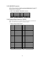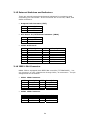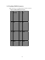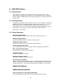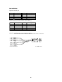
1
NOVA-7820
VIA® C3 Processor CPU
Embedded Board
with 10/100Mbps Ethernet, VGA,
Audio
Version 1.0
Manual Version 1.1
Jul 16, 2003
©Copyright 2003 by ICP Electronics Inc. All Rights Reserved.
Copyright Notice
The information in this document is subject to change without prior notice in
order to improve reliability, design and function and does not represent a
commitment on the part of the manufacturer. In no event will the manufacturer
be liable for direct, indirect, special, incidental, or consequential damages arising
out of the use or inability to use the product or documentation, even if advised of
the possibility of such damages.
This document contains proprietary information protected by copyright. All rights
are reserved. No part of this manual may be reproduced by any mechanical,
electronic, or other means in any form without prior written permission of the
manufacturer.
Trademarks
NOVA-7820 is registered trademarks of ICP Electronics Inc., IBM PC is a
registered trademark of International Business Machines Corporation. Intel is a
registered trademark of Intel Corporation. Award is registered trademarks of
Award Software International, Inc. Other product names mentioned herein are
used for identification purposes only and may be trademarks and/or registered
trademarks of their respective companies.
Support
Any questions regarding the content of this manual or related issues can be emailed to us directly at: [email protected].
2
Table of Contents
1.
Introduction .................................................................. 5
1.1
1.2
Specifications ..................................................................................5
Package Contents ............................................................................6
2.
Installation.................................................................... 7
2.1
2.2
2.3
2.4
2.5
2.6
2.7
NOVA-7820 Layout ..........................................................................7
Clear CMOS Setup ............................................................................9
Compact Flash Setting .....................................................................9
Audio Amplifier Select .....................................................................9
LCD Panel Shift Clock/Panel VCC Select......................................... 10
COM Port RI and Voltage Selection ................................................ 10
COM4 RS232/RS422(485) Selection.............................................. 11
3.
Connection .................................................................. 12
3.1
3.2
3.3
3.4
3.5
3.6
3.7
3.8
3.9
3.10
3.11
3.12
3.13
3.14
3.15
3.16
3.17
3.18
3.19
Floppy Disk Drive Connector .......................................................... 13
Video-in Connector ........................................................................ 13
Ultra ATA33/66/100 IDE Disk Drive Connector ............................. 14
Parallel Port................................................................................... 14
USB Port Connector ....................................................................... 15
Serial Ports .................................................................................... 15
Power Connector ........................................................................... 16
Keyboard Connector ...................................................................... 17
IrDA Infrared Interface Port.......................................................... 17
Fan Connector ............................................................................. 17
Audio Connectors ........................................................................ 18
VGA Connector ............................................................................ 18
LAN RJ45 Connector.................................................................... 19
Compact Flash Connector-TYPE II .............................................. 19
External Switches and Indicators................................................ 20
IEEE-1394 Connector .................................................................. 20
CardBus/PCMCIA Connector ....................................................... 21
Digital I/O .................................................................................. 22
LCD Panel Connector................................................................... 23
4.
AMI BIOS Setup........................................................... 24
4.1
4.2
4.3
4.4
4.5
4.6
4.7
4.8
4.9
4.10
Introduction .................................................................................. 24
Starting Setup................................................................................ 24
Setup Summary ............................................................................. 24
Standard CMOS Setup Selections ................................................... 26
Advanced CMOS Setup Selections .................................................. 27
Advanced Chipset Setup Selections ............................................... 31
Power Management Setup Selections ............................................ 33
PCI / Plug and Play Setup Selections............................................. 35
Peripheral Setup Selections ........................................................... 37
Hardware Monitor Setup Selections ............................................ 39
Appendix A Watchdog Timer .............................................. 40
Appendix B Digital I/O ....................................................... 41
Appendix C Address Mapping ............................................. 42
Appendix D How to Use Wake-up Function ......................... 44
3
Appendix E How to Use Video-in Function ......................... 45
Appendix F How to Use LCD-TYPE Function ........................ 47
4
1. Introduction
Thank you for choosing NOVA-7820 VIA® C3 Processor CPU with Multimedia
& LAN Ethernet Embedded Little Board, which comes equipped with Low
power VIA® C3 Processor CPU with the Intel advanced chipset 815E. This
product is designed for the system manufacturers, integrators, or VARs that
want to build a low power consumption system.
NOVA-7820 provides on-chip VGA which provides up to 1600 x 1200
resolution. LCD which provides up to 1024 x 768 resolution.
An advanced high performance super I/O chip – W83627 and NS87366 is
used in the NOVA-7820 board. Which provide four UARTs are compatible
with the NS16C550. The parallel port and FDD interface are compatible with
IBM PC/AT architecture's.
The NOVA-7820 has one Fast Ethernet Multifunction PCI Controller as a LAN
controller, Which are fully integrated 10BASE-T/100BASE-TX LAN solution
with high performance networking functions and low power features.
This board has a built-in Compact Flash Disk Socket, CardBus, FireWire for
embedded applications.
For multimedia application, NOVA-7820 provides many function, such as
1394 ,5.1 channel Audio and video in.
1.1
Specifications
•
•
•
•
•
•
•
•
•
•
•
•
•
•
CPU: VIA® C3 Processor CPU
DMA channels: 7
Interrupt levels: 15
Chipset: Intel 815E
Memory: One 168-pin DIMM sockets. The memory capability is up to
512MB/133MHz.
Ultra ATA/33/66/100 IDE Interface: One PCI Enhanced IDE channels (2
IDE devices). The south bridge ICH2 supports Ultra ATA/33/66/100 IDE
interface. To support Ultra ATA66/100 Hard disk, a specific cable
(maximum length — 45 cm) is available.
Floppy disk drive interface: Single 2.88 MB, 1.44MB, 1.2MB, 720KB, or
360KB floppy disk drive.
Serial ports: Four high-speed 16C550 compatible UARTs with 16-byte
FIFO buffer. Up to 115 Kbps in speed. And one port supports
RS232/422/485 function.
Parallel Port: One IEEE1284 compatible Bi-directional ports. Supports
SPP/ECP/EPP.
IrDA: Supports Serial Infrared(SIR) and Amplitude Shift Keyed
IR(ASKIR) interface.
USB: Supports two USB 1.1 compatible ports.
Audio: Onboard CMI8738 chipset, Supports 5.1 channel sound, that
include LINEOUT, REAR, and CENTER/BASS.
Watchdog timer: Software programmable — enable/disabled. Timer
interval is 1 ~ 255 seconds. System Reset will be generated when time
out.
VGA Controller: Embedded VGA controller. Screen Resolution: up to
5
•
•
•
•
•
•
•
•
•
1.2
1600 x 1200 in 256 Colors at 85 Hz Refresh.
LCD Controller: Onboard SP1015 LCD controller. Screen Resolution: up
to 1024 x 768 36bits.
Intel 82801BA embedded LAN: IEEE 802.3u Auto-Negotiation support
for 10BASE-T/100BASE-TX. Fast back-to-back transmission support
with minimum interframe spacing. Connected to your LAN through
RJ45 connector.
Keyboard Controller: 8042 compatible for keyboard and PS/2 mouse
4 Digital Inputs and 4 Digital Outputs.
4 Channels of composite video input.
FireWire: TSB43AA22 provides the digital and analog transceiver
functions to implement a two-port node in a cable-based IEEE 1394.
Provides two P1394a fully compliant cable ports at 100/200/400
megabits per second (Mbits/s).
CardBus: Compliant with CardBus/PCMCIA PC Card 95/97 standard
specification.
Power Consumption: 5V/3.0A and 12V/0.22A, as running by VIA Eden
ESP 4000(400MHz) and 256MB SDRAM.
Operating Temperature: 0 ℃ ~ 60 ℃ (CPU needs heatsink)
Package Contents
In addition to this User Manual, NOVA-7820 package includes the following
items:
•
•
•
•
•
•
•
•
•
NOVA-7820 Mobile CPU bases Single board computer x 1
FDD cable x 1
HDD cable x 1
Keyboard / Mouse adapter Y cable
Two RS-232 serial ports and RS-232/422/485 serial port cable x 1
Printer port cable x 1
AUDIO ports cable x 1
4-channel composite video cable x 2
IEEE-1394 cable x 1
6
2. Installation
Follow the instructions of installing NOVA-7820. Read the unpacking
information carefully before installation.
2.1
NOVA-7820 Layout
7
8
2.2
Clear CMOS Setup
CMOS RAM holds the configuration data of NOVA-7820, which has to be
set by means of system BIOS. To clear CMOS RAM, close JP1 for about 3
seconds, and then open it again. It will then resume to normal mode.
•
JP1: Clear CMOS Setup
JP1
1-2
2-3
2.3
Description
Keep CMOS Setup
(Normal Operation)
Clear CMOS Setup
Compact Flash Setting
Set the operating mode of Compact Flash disk. This is similar to the
operation of hard disk.
•
JP2: Compact Flash Setting
JP2
OPEN
Close
2.4
Description
Slave
Master
Audio Amplifier Select
This jumper is for the setting of Audio Amplifier.
•
JP5: Audio L_Line out select
JP5
1-2
2-3
•
Description
OFF
ON
JP6: Audio R_Line out select
JP6
1-2
2-3
Description
OFF
ON
9
2.5
LCD Panel Shift Clock/Panel VCC Select
This jumper is for the setting of LCD panel shift clock mode and panel
power voltage.
•
JP7: LCD Panel Shift Clock
JP7
1-3
3-5
•
JP7: Panel VCC
JP7
2-4
4-6
2.6
Description
Inverted
Normal
Description
+5V
+3.3V
COM Port RI and Voltage Selection
JP8 is setting COM3, 4 RI and Voltage.
•
JP8: Set pin 9 of COM3 as signal RI or voltage source
JP8
10-12
8-10
•
JP8: Set pin 9 of COM4 as signal RI or voltage source
JP8
9-11
7-9
•
Description
COM4 RI Pin Use RI
COM4 RI Pin Use Voltage
JP8: Set pin 9 of COM3 as +5V or 12V
JP8
2-4
4-6
•
Description
COM3 RI Pin Use RI
COM3 RI Pin Use Voltage
Description
COM3 RI Pin Use Voltage +5V
COM3 RI Pin Use Voltage +12V
JP8: Set pin 9 of COM4 as +5V or 12V
JP8
1-3
3-5
Description
COM4 RI Pin Use Voltage +5V
COM4 RI Pin Use Voltage +12V
10
2.7
COM4 RS232/RS422(485) Selection
•
JP9: Selection COM4 is RS232/RS422(485)
JP9
1-2
2-3
•
Description
RS232
RS422/485
JP10: Selection COM4 is RS422/RS485
JP10
RS422
RS485
Description
1-3
2-4
OFF
OFF
ON
ON
11
3. Connection
This chapter describes how to connect peripherals, switches and indicators to
the NOVA-7820 board. The following table lists the connectors on NOVA7820.
Label
CDIN1
CN1
CN2
CN7
CN8,11
CN12
CN16
CN20
CN21,36
CN24
CN26
CN30
CN32
CN33
CN35
CN37
CN43
CN44
CN45
CN47
CN48,49
CON1
FAN1,3
IR1
PCI1
Description
CD-IN Connector
Parallel Port Connector
IDE Connector
SUS LED
Serial Port 1,2
ATX Power On/Off Button Connector
DIN Connector for Keyboard/Mouse
External Switch and Indicators
IEEE-1394 Connector
FDD Connector
ATX Power Connector
Power Connector
Audio Connector
4 Channels of composite video in Connector
USB Connector
LAN Connector
Compact Flash
CardBus/PCMCIA Connector
Digital I/O
LCD Connector
Serial Port 3,4
VGA Connector
Fan Connectors
IrDA Connector
Specific PCI Slot
12
3.1
Floppy Disk Drive Connector
NOVA-7820 board is equipped with a 34-pin daisy-chain driver connector
cable.
•
CN24: FDD Connector
PIN
1
3
5
7
9
11
13
15
17
19
21
23
25
27
29
31
33
3.2
Description
GROUND
GROUND
GROUND
GROUND
GROUND
GROUND
GROUND
GROUND
GROUND
GROUND
GROUND
GROUND
GROUND
GROUND
N/C
GROUND
N/C
PIN
2
4
6
8
10
12
14
16
18
20
22
24
26
28
30
32
34
Description
REDUCE WRITE
N/C
DS1#
INDEX#
MOTOR ENABLE A#
DRIVE SELECT B#
DRIVE SELECT A#
MOTOR ENABLE B#
DIRECTION#
STEP#
WRITE DATA#
WRITE GATE#
TRACK 0#
WRITE PROTECT#
READ DATA#
SIDE 1 SELECT#
DISK CHANGE#
Video-in Connector
NOVA-7820 is equipped witch 4 channels of composite video
connector(BT878A).
•
CN33: Capture IN
PIN
1
3
5
7
Description
AVIN0
AVIN1
AVIN2
AVIN3
PIN
2
4
6
8
13
Description
GROUND
GROUND
GROUND
GROUND
3.3
Ultra ATA33/66/100 IDE Disk Drive Connector
You can attach one IDE (Integrated Device Electronics) hard disk drives to
the NOVA-7820 IDE controller.
•
CN2: Primary IDE Connector
PIN
1
3
5
7
9
11
13
15
17
19
21
23
25
27
29
31
33
35
37
39
3.4
Description
RESET#
DATA 7
DATA 6
DATA 5
DATA 4
DATA 3
DATA 2
DATA 1
DATA 0
GROUND
N/C
IOW#
IOR#
CHRDY
DACK
INTERRUPT
SA1
SA0
HDC CS0#
HDD ACTIVE#
PIN
2
4
6
8
10
12
14
16
18
20
22
24
26
28
30
32
34
36
38
40
Description
GROUND
DATA 8
DATA 9
DATA 10
DATA 11
DATA 12
DATA 13
DATA 14
DATA 15
N/C
GROUND
GROUND
GROUND
GROUND
GROUND
GROUND
P66DET
N/C
HDC CS1#
GROUND
Parallel Port
This port is usually connected to a printer. NOVA-7820 includes an onboard parallel port, and accessed through a 26-pin flat-cable connector
CN1. Three modes: SPP, EPP and ECP are supported.
•
CN1: Parallel Port Connector
PIN
1
2
3
4
5
6
7
8
9
10
11
12
13
Description
STROBE#
DATA 0
DATA 1
DATA 2
DATA 3
DATA 4
DATA 5
DATA 6
DATA 7
ACKNOWLEDGE
BUSY
PAPER EMPTY
PRINTER SELECT
PIN
14
15
16
17
18
19
20
21
22
23
24
25
26
14
Description
AUTO FORM FEED #
ERROR#
INITIALIZE
PRINTER SELECT LN#
GROUND
GROUND
GROUND
GROUND
GROUND
GROUND
GROUND
GROUND
N/C
3.5
USB Port Connector
NOVA-7820 provides two USB ports (USB 1.1 compliant).
•
CN35: USB 8-PIN HEADER
PIN
A1
A2
A3
A4
B1
B2
B3
B4
3.6
Description
VCC
DATA0DATA0+
GROUND
VCC
DATA0DATA0+
GROUND
Serial Ports
NOVA-7820 offers four high speed NS16C550 compatible UARTs with
Read/Receive 16 byte FIFO in each serial port.
•
CN8: D_SUB 9-PIN Connector
PIN
1
2
3
4
5
6
7
8
9
•
Description
DATA CARRIER DETECT (DCD)
RECEIVE DATA (RXD)
TRANSMIT DATA (TXD)
DATA TERMINAL READY (DTR)
GROUND
DATA SET READY (DSR)
REQUEST TO SEND (RTS)
CLEAR TO SEND (CTS)
RING INDICATOR (RI)
CN11: 10-pin Connector
PIN
1
2
3
4
5
6
7
8
9
10
Description
DATA CARRIER DETECT (DCD)
RECEIVE DATA (RXD)
TRANSMIT DATA (TXD)
DATA TERMINAL READY (DTR)
GROUND
DATA SET READY (DSR)
REQUEST TO SEND (RTS)
CLEAR TO SEND (CTS)
RING INDICATOR (RI)
N/C
15
•
CN48: 10-pin Connector
PIN
1
2
3
4
5
6
7
8
9
10
•
CN49: 14-pin Connector
PIN
1
2
3
4
5
6
7
8
9
10
11
12
13
14
3.7
Description
DATA CARRIER DETECT (DCD)
RECEIVE DATA (RXD)
TRANSMIT DATA (TXD)
DATA TERMINAL READY (DTR)
GROUND
DATA SET READY (DSR)
REQUEST TO SEND (RTS)
CLEAR TO SEND (CTS)
RING INDICATOR (RI)
N/C
Description
DATA CARRIER DETECT (DCD)
RECEIVE DATA (RXD)
TRANSMIT DATA (TXD)
DATA TERMINAL READY (DTR)
GROUND
DATA SET READY (DSR)
REQUEST TO SEND (RTS)
CLEAR TO SEND (CTS)
RING INDICATOR (RI)
N/C
TX+ (RS422/485)
TX- (RS422/485)
RX+ (RS422/485)
RX- (RS422/485)
Power Connector
NOVA-7820 has one power connector for power supply.
•
CN30: Power Supply Connector
PIN
1
2
3
4
•
Description
VCC12V
GROUND
GROUND
VCC5V
CN26: ATX Power Connector
PIN
1
2
3
Description
VCC5VSB
PS_ON
GROUND
16
3.8
Keyboard Connector
NOVA-7820 provides 6-PIN MIN-DIN keyboard/mouse connector.
•
CN16: 6-pin Mini-DIN Keyboard/Mouse Connector
PIN
1
2
3
4
5
6
3.9
Description
KEYBOARD DATA
MOUSE DATA
GROUND
+5V
KEYBOARD CLOCK
MOUSE CLOCK
IrDA Infrared Interface Port
NOVA-7820 has a built-in IrDA port which supports Serial Infrared (SIR) or
Amplitude Shift Keyed IR (ASKIR) interface. To use the IrDA port, set SIR
or ASKIR model in COM 2 of BIOS Peripheral Setup. Then the normal RS232 COM 2 will be disabled.
•
IR1: IrDA Connector
PIN
1
2
3
4
5
Description
VCC5V
N/C
IR-RX
GROUND
IR-TX
3.10 Fan Connector
NOVA-7820 provides CPU cooling fan connector and system fan connector.
CPU connectors can supply 12V/500mA. The Fan’s rotation is in full speed.
•
FAN1, FAN3: Fan Connector
PIN
1
2
3
Description
SENSOR
12V
GROUND
17
3.11 Audio Connectors
NOVA-7820 has a built-in AUDIO chipset (CMEDIA CMI8738LX); connector
directly connects to the pin-header (CN32). The audio chipset can support
5.1 channel sounds that include LINE-OUT, REAR, and CENTER/BASS.
•
CN32: Audio Connector (2x8_2.00mm)
PIN
1
3
5
7
9
11
13
15
•
Description
LINEOUT_L
LINEOUT_R
CENTER
GROUND
LININ_L
GROUND
REAR_L
MIN_IN
PIN
2
4
6
8
10
12
14
16
Description
GROUND
GROUND
BASS
GROUND
LINEIN_R
GROUND
REAR_R
GROUND
CDIN1: CD-IN
PIN
1
2
3
4
Description
CD LEFT SIGNAL
GROUND
GROUND
CD RIGHT SIGNAL
3.12 VGA Connector
NOVA-7820 has a built-in 15-pin VGA connector directly to your CRT
monitor.
•
CON1: 15-pin Female Connector
PIN
1
3
5
7
9
11
13
15
Description
RED
BLUE
GROUND
GROUND
VCC
N/C
HSYNC
DDCCLK
PIN
2
4
6
8
10
12
14
Description
GREEN
N/C
GROUND
GROUND
GROUND
DDC DAT
VSYNC
18
3.13 LAN RJ45 Connector
NOVA-7820 is equipped with built-in one 10/100Mbps Ethernet Controller.
You can connect it to your LAN through RJ45 LAN connector. The pin
assignments are as following:
•
CN37 : Intel 82562ET LAN RJ45 Connector
PIN
1
2
3
4
Description
TX+
TXRX+
N/C
PIN
5
6
7
8
Description
N/C
RXN/C
N/C
3.14 Compact Flash Connector-TYPE II
NOVA-7820 supports one Compact Flash socket that be provided from
IDE2. You must set the jumper to avoid the conflict.
•
CN43: Compact Flash Socket
PIN
1
2
3
4
5
6
7
8
9
10
11
12
13
14
15
16
17
18
19
20
21
22
23
24
25
Description
GROUND
DATA3
DATA4
DATA5
DATA6
DATA7
HDC_CS0#
N/C
GROUND
N/C
N/C
N/C
+5V
N/C
N/C
N/C
N/C
SA2
SA1
SA0
DATA0
DATA1
DATA2
N/C
VCC-IN CHECK2
PIN
26
27
28
29
30
31
32
33
34
35
36
37
38
39
40
41
42
43
44
45
46
47
48
49
50
19
Description
VCC-IN CHECK2
DATA11
DATA12
DATA13
DATA14
DATA15
HDC_CS1#
N/C
IOR#
IOW#
N/C
INTERRUPT
+5V
CSEL
N/C
RESET#
IORDY
N/C
+5V
HDD_ACTIVE#
N/C
DATA8
DATA9
DATA10
GROUND
3.15 External Switches and Indicators
There are several external switches and indicators for monitoring and
controlling your CPU board. All the functions are in the CN7, CN12, and
CN20 connectors.
•
Suspend Led Connector (CN7)
PIN
1
2
•
ATX Power On/Off Button Connector (CN12)
PIN
1
2
•
Description
LED+
LED-
Description
PWR_BUTTON+
GROUND
CN20: Multi Panel
PIN
1
3
5
7
9
11
13
Description
POWER-LED +
N/C
POWER-LED KEYLOCK+
KEYLOCKGROUND
HDD LED+
PIN
2
4
6
8
10
12
14
Description
SPEAKER N/C
N/C
SPEAKER +5V
RESET SW
RESET SW GND
HDD LED -
3.16 IEEE-1394 Connector
NOVA-7820 is equipped witch IEEE1394 controller (TI TSB43AA22). You
can connect it to your 1394 device through CN21, 36 connectors. The pin
assignments are as follows:
•
CN21: 1394 Connector
PIN
1
3
5
7
•
Description
VCC12V
TPBTPANC/FG
PIN
2
4
6
8
Description
GROUND
TPB+
TPA+
NC/FG
PIN
2
4
6
Description
GROUND
TPB+
TPA+
CN36: 1394 Connector
PIN
1
3
5
Description
VCC12V
TPBTPA-
20
3.17 CardBus/PCMCIA Connector
NOVA-7820 built-in a CardBus/PCMCIA interface connector.
•
CN44: CardBus/PCMCIA Connector
PIN
1
3
5
7
9
11
13
15
17
19
21
23
25
27
29
31
33
35
37
39
41
43
45
47
49
51
53
55
57
59
61
63
65
67
69
Description
GROUND
D4
D6
CE1#
OE#
A9
A13
WE#
VCC
A16
A12
A6
A4
A2
A0
D1
WP
GROUND
D11
D13
D15
VS1#
IOWR#
A18
A20
VCC
A22
A24
VS2#
WAIT#
REG#
BVD1
D9
CD2#
GROUND
PIN
2
4
6
8
10
12
14
16
18
20
22
24
26
28
30
32
34
36
38
40
42
44
46
48
50
52
54
56
58
60
62
64
66
68
70
Description
D3
D5
D7
A10
A11
A8
A14
READY
VCC
A15
A7
A5
A3
A1
D0
D2
GROUND
CD1#
D12
D14
CE2#
IORD#
A17
A19
A21
VCC
A23
A25
RESET
INPACK#
BVD2
D8
D10
GROUND
GROUND
21
3.18 Digital I/O
One characteristic of digital circuit is its fast response to high or low signal.
This kind of response is highly needed for harsh and critical industrial
operating environment. That’s why we design 4-bit digital inputs and 4-bit
digital outputs on NOVA-7820.
Digital Input and Output, generally, are control signals. You can use these
signals to control external devices that needs On/Off circuit or TTL devices.
We provide "BIOS Call" for DIO reading.
READ
Bit0
DIN0
Bit1
DIN1
Bit2
DIN2
Bit3
DIN3
•
WRITE
Bit0
DO0
Bit1
DO1
Bit2
DO2
Bit3
DO3
CN45: Digital I/O
PIN
1
3
5
7
9
Description
GROUND
DO3
DO1
DIN3
DIN1
PIN
2
4
6
8
10
22
Description
VCC5V
DO2
DO0
DIN2
DIN0
3.19 LCD Panel Connector
NOVA-7820 provides a 2 x 25-pin connector for the LCD flat panel
interface. NOVA-7820 supports TFT LCD panels at following display
options:
Video Display Type
Resolution
Example
TFT VGA
640 x 480, 18 bits
Toshiba LTM10C209H
TFT SVGA
800 x 600, 18 bits
Toshiba LTM12C275C
TFT XVGA
1024 x 768, 18 bits
L.G LM151X2
Note that the table is for reference only. The LCD panel connector of
NOVA-7820 may support more panel types.
•
CN47: LCD Panel Connector for SP1015
PIN
1
3
5
7
9
11
13
15
17
19
21
23
25
27
29
31
33
35
37
39
41
43
45
47
49
Description
N/C
BB2
BB3
BB4
BB5
BB6
BB7
RA7
GB2
GB3
RA3
GA5
GA7
BA7
Panel-VCC
GB4
BA4
BA3
BA2
RM
Shift Clock
FPVDD
Enable VEE
GND
Inverter VCC
PIN
2
4
6
8
10
12
14
16
18
20
22
24
26
28
30
32
34
36
38
40
42
44
46
48
50
23
Description
RB2
RB3
RB4
RB5
RB6
RB7
RA5
RA6
RA4
RA2
GA6
GA4
GA3
GA2
Panel-VCC
GB5
BA6
BA5
GB6
GB7
Enable Backlight
FLM
LP
GND
Inverter VCC
4. AMI BIOS Setup
4.1 Introduction
This chapter discusses the Setup program built into the BIOS. which
allows users to configure the system. This configuration is then stored in
battery-backed CMOS RAM so that Setup information is retained whilst the
power is off.
4.2 Starting Setup
The BIOS is immediately active when you turn on the computer. While the
BIOS is activated, the Setup program can be entered in one of two ways:
By pressing <Del> immediately after switching the system on, or
by pressing the <Del> key when the following message appears briefly at
the bottom of the screen during the POST (Power On Self-Test).
Press DEL to run SETUP.
4.3 Setup Summary
Standard CMOS Setup:
Standard CMOS Setup to change time, date, hard disk type, etc.
Advanced CMOS Setup:
Advanced CMOS Setup to configure system options.
Advanced Chipset Setup:
Advanced Chipset Setup to configure chipset features.
Power Management Setup:
Power Management Setup to configure power management features.
PCI / Plug and Play Setup:
Configures PCI / Plug and Play features.
Peripheral Setup:
Configures peripheral features.
Hardware Monitor Setup:
Configures hardware monitor features.
Auto-Detect Hard Disks:
Selecting these options allow the user to configure the drive named in the
option. Select Auto-Detect Hard Disks to allow AMIBIOS to automatically
configure the drive. A list of drive parameters will appear on the screen.
Change User Password:
Change the user password.
Change Supervisor Password:
Change the supervisor password.
Auto Configuration with Optimal Settings:
Load configuration settings that ensure the highest performance.
24
Auto Configuration with Fail Safe Settings:
Load fails-safe configuration settings.
Save Settings and Exit:
Write the current settings to CMOS and exit.
Exit Without Saving:
Exit without saving the current settings.
AMIBIOS HIFLEX SETUP UTILITY – VERSION 1.52
(C) 2001 American Megatrends, Inc. All Rights Reserved
NOVA-7820 V1.0 (02/11/2003)
Standard CMOS Setup
Advanced CMOS Setup
Advanced Chipset Setup
Power Management Setup
PCI / Plug and Play Setup
Peripheral Setup
Hardware Monitor Setup
Auto-Detect Hard Disks
Change User Password
Change Supervisor Password
Auto Configuration with Optimal Settings
Auto Configuration with Fail Safe Settings
Save Settings and Exit
Exit Without Saving
Standard CMOS Setup for changing time, date, hard disk type, etc.
ESC: Exit ↑↓: Sel F2/F3: Color F10: Save & Exit
Figure 1: Main Menu
25
4.4 Standard CMOS Setup Selections
AMIBIOS SETUP – STANDARD CMOS SETUP
(C) 2001 American Megatrends, Inc. All Rights Reserved
Date (mm/dd/yyyy): Tue Mar 19,2002
Time (hh/mm/ss): 17:18:10
Floppy Drive A:
Floppy Drive B:
Base Memory: 639 KB
Extd Memory: 247 MB
Not Installed
Not Installed
Type
Pri Master: Auto
Pri Slave : Auto
Sec Master: Auto
Sec Slave : Auto
Size
LBA Blk PIO 32Bit
Cyln Head WPcom Sec Mode Mode Mode Mode
On
On
On
On
Boot Sector Virus Protection
Disabled
Month: Jan – Dec
Day: 01 – 31
Year: 1980 – 2099
ESC: Exit ↑↓: Sel
PgUp/PgDn: Modify
F1: Help F2/F3: Color
Figure 2: Standard CMOS Setup
Date (mm/dd/yyyy)
Set the system date.
Time (hh/mm/ss)
Set the system time.
Floppy A, B
Move the cursor to these fields and select the floppy type.
Primary/Secondary Master/Slave LBA Mode
LBA (Logical Block Addressing) is a new IDE HDD access method to develop
to overcome the 528-megabyte capacity bottleneck. If your IDE hard disk
capacity is greater than 528MB, AMIBIOS can enable this LBA mode feature.
The option is only for Primary Master IDE LBA mode.
Primary/Secondary Master/Slave Block Mode
If your hard disk drive supports IDE block transfer mode, enable this option
for a faster IDE hard disk drive transfer rate. The option is only for
Primary Master Block mode.
Primary/Secondary Master/Slave PIO Mode
This option enables Primary Master IDE PIO mode on the IDE, which can
set proper cycle timings. The cycle timing between the IDE PIO mode value
and IDE cycle timing is shown below :
Mode 0 -> Timing ( 600ns )Mode 1 -> Timing ( 383ns )
Mode 2 -> Timing ( 240ns )Mode 3 -> Timing ( 180ns )
Mode 4 -> Timing ( 120ns )Mode 5 -> Timing ( 60ns )
26
Primary/Secondary Master/Slave 32Bit Mode
This option enables Primary Master IDE 32-bit data transfers on the IDE
data port. If disabled,16-bit data transfer is used by the BIOS.32-bit data
transfers can only be enabled if IDE prefetch mode is also enabled.
Boot Sector Virus Protection
When this option is enabled, AMIBIOS issues a warning when any program
or virus issues a Disk Format command or attempts to write to the boot
sector of the hard disk drive. The settings are Disabled, or Enabled.
Base/Extd Memory
Displays the amount of conventional/extended memory detected during
boot up.
4.5 Advanced CMOS Setup Selections
AMIBIOS SETUP – ADVANCED CMOS SETUP
(C) 2001 American Megatrends, Inc. All Rights Reserved
Quick Boot
1st Boot Device
2nt Boot Device
3rd Boot Device
Try Other Boot Devices
LAN Boot ROM
Floppy Access Control
Hard Disk Access Control
S.M.A.R.T. for Hard Disks
BootUP Num-Lock
Floppy Drive Seek
PS/2 Mouse Support
System Keyboard
Primary Display
Password Check
Boot To OS/2
Wait For ‘F1’ If Error
Hit ‘DEL’ Message Display
L1 Cache
L2 Cache
System BIOS Cacheabled
C000 16K Shadow
C400 16K Shadow
C800 16K Shadow
CC00 16K Shadow
D000 16K Shadow
D400 16K Shadow
D800 16K Shadow
DC00 16K Shadow
Enabled
Disabled
Disabled
Disabled
Yes
Disabled
Read-Write
Read-Write
Disabled
On
Disabled
Enabled
Present
VGA/EGA
Setup
No
Enabled
Enabled
WriteBack
WriteBack
Disable
Enabled
Enabled
Enabled
Disabled
Disabled
Disabled
Disabled
Disabled
Figure 3: Advanced CMOS Setup
27
Available Options:
Disabled
> Enabled
ESC: Exit ↑↓: Sel
PgUp/PgDn: Modify
F1: Help F2/F3: Color
Quick Boot
When Quick Boot is selected, DRAM testing function will be disabled.
1st Boot Device
This option sets the type of device for the first boot drives that the
AMIBIOS attempts to boot from after AMIBIOS POST completes. The
settings are Disabled, IDE-0, IDE-1, IDE-2, IDE-3, Floppy, ARMD-FDD,
ARMD-HDD, CDROM, and SCSI.
2nd Boot Device
This option sets the type of device for the second boot drives that the
AMIBIOS attempts to boot from after AMIBIOS POST completes. The
settings are Disabled, IDE-0, IDE-1, IDE-2, IDE-3, Floppy, ARMD-FDD,
ARMD-HDD, and CDROM.
3rd Boot Device
This option sets the type of device for the third boot drives that the
AMIBIOS attempts to boot from after AMIBIOS POST completes. The
settings are Disabled, IDE-0, IDE-1, IDE-2, IDE-3, Floppy, ARMD-FDD,
ARMD-HDD, and CDROM.
Try Other Boot Devices
Set this option to Yes to instruct AMIBIOS to attempt to boot from any
other drive in the system if it cannot find a boot drive among the drives
specified in the 1st Boot Device, 2nd Boot Device, 3rd Boot Device, 4th Boot
Device options. The settings are Yes or No.
Floppy Access Control
This option specifies the read/write access that is set when booting from a
floppy drive.
Hard Disk Access Control
This option specifies the read/write access that is set when booting from a
hard disk drive.
S.M.A.R.T. for Hard Disks
Self-Monitoring, Analysis and Reporting Technology. This option can help
the BIOS to warn the user of a possible device failure and give the user a
chance to back up the device before the failure actually happens. The
settings are Auto, Disabled, Enabled.
Floppy Drive Seek
Set this option to Enabled to specify that floppy drive A: will perform a Seek
operation at system boot. The settings are Enabled or Disabled.
BootUp Num-Lock
When this option is selected, Num Lock is turned off when the system is
powered on so the user can use the arrow keys on both the numeric
keypad and the keyboard.
PS/2 Mouse Support
When this option is enabled, BIOS supports a PS/2- type mouse.
System Keyboard
This option does not specify if a keyboard is attached to the computer.
Rather, it specifies if error messages are displayed if a keyboard is not
attached. This option permits you to configure workstation with no
28
keyboard. The settings are Absent, Present.
Primary Display
Select this option to configure the type of monitor attached to the computer.
The settings are Monochrome, Color 40x25, Color 80x25, VGA/PGA/EGA, or
Not Install.
Password Check
This item allows you Setup/Always Password Check.
Boot To OS/2
Set this option to Enabled if running OS/2 operating system and using more
than 64MB of system memory on the motherboard. The settings are
Disabled or Enabled.
Wait For 'F1' If Error
If this option is enabled, AMIBIOS waits for the end user to press <F1>
before continuing. If this option is disabled, AMIBIOS continues the boot
process without waiting for <F1> to be pressed. The settings are Disabled
or Enabled.
Hit 'DEL' Message Display
Disabling this option prevents "Hit <DEL> if you want to run Setup" from
appearing when the system boots. The settings are Disabled or Enabled.
L1 Cache
The options include Disable/WriteThru/WriteBack the internal cache memory
in the processor.
L2 Cache
The options include Disable/WriteThru/WriteBack the secondary cache
memory.
System BIOS Cacheable
When this option is set to Enabled, the System ROM area from F0000-FFFFF
is copied (shadowed) to the RAM for faster execution.
C000, 16k Shadow
When this option is set to Enabled, the Video ROM area from C0000-C3FFF
is copied (shadowed) to the RAM for faster execution.
Disabled: The contents of the video ROM are not copied to the RAM.
Cached: The contents of the video ROM area from C0000h - C3FFFh are
copied from the ROM to the RAM and can be written to or read from the
cache memory.
Enabled: The contents of the video ROM area from C0000h - C3FFFh are
copied (shadowed) from the ROM to the RAM for faster execution.
C400, 16k Shadow
When this option is set to Enabled, the Video ROM area from C4000-C7FFF
is copied (shadowed) to the RAM for faster execution.
Disabled: The contents of the video ROM are not copied to the RAM.
Cached: The contents of the video ROM area from C4000h - C7FFFh are
copied from the ROM to the RAM and can be written to or read from the
cache memory.
Enabled: The contents of the video ROM area from C4000h - C7FFFh are
copied (shadowed) from the ROM to the RAM for faster execution.
29
C800, 16k Shadow
These options enable shadowing of the contents of the ROM area named in
the option title. The settings are Enabled, Disabled, and Cached. The ROM
area that is not used by ISA adapter cards will be allocated to PCI adapter
cards.
CC00, 16k Shadow
These options enable shadowing of the contents of the ROM area named in
the option title. The settings are Enabled, Disabled, and Cached. The ROM
area that is not used by ISA adapter cards will be allocated to PCI adapter
cards.
D000, 16k Shadow
These options enable shadowing of the contents of the ROM area named in
the option title. The settings are Enabled, Disabled, and Cached. The ROM
area that is not used by ISA adapter cards will be allocated to PCI adapter
cards.
D400, 16k Shadow
These options enable shadowing of the contents of the ROM area named in
the option title. The settings are Enable Disable, Cached. The ROM area
that is not used by ISA adapter cards will be allocated to PCI adapter cards.
D800, 16k Shadow
These options enable shadowing of the contents of the ROM area named in
the option title. The settings are Enable Disable, Cached. The ROM area
that is not used by ISA adapter cards will be allocated to PCI adapter cards.
DC00, 16k Shadow
These options enable shadowing of the contents of the ROM area named in
the option title. The settings are Enable Disable, Cached. The ROM area
that is not used by ISA adapter cards will be allocated to PCI adapter cards.
30
4.6 Advanced Chipset Setup Selections
AMIBIOS SETUP – ADVANCED CHIPSET SETUP
(C) 2001 American Megatrends, Inc. All Rights Reserved
Memory Hole
Disabled
SDRAM Timing by SPD
Disabled
DRAM Refresh
15.6uS
DRAM Cycle time (SCLKs)
7/9
CAS# Latency (SCLKs)
3
RAS to CAS delay (SCLKs)
3
SDRAM RAS# Precharge (SCLKs)
3
Internal Graphics Mode Size
1MB
Display Cache Window Size
64MB
AGP Aperture Window
64MB
USB Function
All USB Port
USB Device Legacy Support
Disabled
Port 64/60 Emulation
Disabled
Available Options:
> Disabled
Enabled
ESC: Exit ↑↓: Sel
PgUp/PgDn: Modify
F1: Help F2/F3: Color
Figure 4: Advanced Chipset Setup
Memory Hold
This field allows you to reserve an address space for ISA devices that
require it. Configuration options: [Disabled] [15MB-16MB]
SDRAM Timing by SPD
This sets the optimal timings for items "DRAM Refresh", "DRAM Cycle time",
"CAS# Latency", "RAS to CAS delay" and "SDRAM RAS# Precharge",
depending on the memory modules that you are using.
DRAM Cycle time (SCLKs)
This feature controls the number of SDRAM clocks used for SDRAM
parameters Tras and Trc. Tras specifies the minimum clocks required
between active command and precharge command. Trc specifies the
minimum clocks required between active command and re-active command.
CAS# Latency (SCLs)
This controls the latency between the SDRAM read command and the time
that the data actually becomes available.
RAS to CAS Delay (SCLKs)
This controls the latency between the SDRAM active command and the
read/write command.
SDRAM RAS# Precharge (SCLKs)
This controls the idle clocks after issuing a precharge command to the
SDRAM.
Display Cache Window Size
This feature allows you to select the size of mapped memory for Display
Cache data.
31
AGP Aperture Window
This feature allows you to select the size of mapped memory for AGP
graphic data.
USB Function
Select Enabled if your system contains a Universal Serial Bus (USB)
controller and you have USB peripherals.
USB Device Legacy Support
This motherboard support Universal Serial Bus (USB) devices. If detected,
USB controller legacy mode will be enabled. If not detected, USB controller
legacy mode will be disabled.
32
4.7 Power Management Setup Selections
AMIBIOS SETUP – POWER MANAGEMENT SETUP
(C) 2001 American Megatrends, Inc. All Rights Reserved
ACPI Aware O/S
Sleep State
USB KB/MS wakeup From S3
Power Management/APM
Suspend Time Out
Throttle Slow Clock Temperature
Throttle Slow Clock Ratio
Keyboard & PS/2 Mouse
FDC/LPT/COM Ports
SB & MSS Audio Ports
MIDI Ports
ADLIB Ports
Primary Master IDE
Primary Slave IDE
Secondary Master IDE
Secondary Slave IDE
System Thermal
Power Button Function
Restore on AC/Power Loss
Wake Up On Ring
Wake Up On Lan
Wake Up On PME
Resume By Alarm
Alarm Date
Alarm Hour
Alarm Minute
Alarm Second
Power Type Select
No
S1/POS
Disable
Enabled
Disabled
65℃/149℉
50.0%
Monitor
Monitor
Ignore
Ignore
Ignore
Monitor
Ignore
Monitor
Ignore
Ignore
ON/Off
Last State
Disabled
Disabled
Disabled
Disabled
15
12
30
30
AT
Available Options:
> No
Yes
ESC: Exit ↑↓: Sel
PgUp/PgDn: Modify
F1: Help F2/F3: Color
Figure 5: Power Management Setup
ACPI Aware O/S
This feature is switch of ACPI function.
Sleep State
This feature is switch of STR (S3) or POS (S1) function.
USB KB/MS wakeup From S3
This option set to "Enabled", using USB keyboard or USB mouse can wake
up system, when system entry to S3 mode.
Power Management/APM
Set this option to Enabled to run APM (Advanced Power Management).
Suspend Time Out
This option specifies the length of a period of system inactivity while in
Standby state. When this length of time expires, the computer enters
Suspend power state.
Keyboard & PS/2 Mouse
Enabling the option allows the IRQ input to be monitored for both
inactivating for entering Auto_mode/SMI_mode and activating for entering
Normal mode.
33
FDC/LPT/COM Ports
Enabling the option allows the IRQ input to be monitored for both
inactivating for entering Auto_mode/SMI_mode and activating for entering
Normal_mode.
SB & MSS Audio Ports
Enabling the option allows the IRQ input to be monitored for both
inactivating for entering Auto_mode/SMI_mode and activating for entering
Normal_mode.
MIDI Ports
Enabling the option allows the IRQ input to be monitored for both
inactivating for entering Auto_mode/SMI_mode and activating for entering
Normal_mode.
ADLIB Ports
Enabling the option allows the IRQ input to be monitored for both
inactivating for entering Auto_mode/SMI_mode and activating for entering
Normal_mode.
Primary Master IDE
Enabling the option allows the IRQ input to be monitored for both
inactivating for entering Auto_mode/SMI_mode and activating for entering
Normal_mode.
Primary Slave IDE
Enabling the option allows the IRQ input to be monitored for both
inactivating for entering Auto_mode/SMI_mode and activating for entering
Normal_mode.
Secondary Master IDE
Enabling the option allows the IRQ input to be monitored for both
inactivating for entering Auto_mode/SMI_mode and activating for entering
Normal_mode.
Secondary Slave IDE
Enabling the option allows the IRQ input to be monitored for both
inactivating for entering Auto_mode/SMI_mode and activating for entering
Normal_mode.
Power Button Function
This option specifies how the power button mounted externally on the
computer chassis is used.
Wake Up On Ring
Ring Resume From Soft Off
Wake Up On Lan
LAN Resume From Soft Off
Wake Up On PME
PME# Resume From Soft Off
Resume By Alarm
When this option is set enabled, system will according to you set time then
wakeup from soft off mode.
34
Alarm Date
You can set time for date.
Alarm Hour
You can set time for hour.
Alarm Minute
You can set time for minute.
Alarm Second
You can set time for second.
Power Type Select
Select you use power type.
4.8 PCI / Plug and Play Setup Selections
AMIBIOS SETUP – PCI / PLUG AND PLAY SETUP
(C)2001 American Megatrends, Inc. All Rights Reserved
Plug and Play Aware O/S
Clear NVRAM on Every Boot
On Board Audio Controller
On Board IEEEE1394 Controller
On Board PCMCIA Controller
PCI Latency Timer (PCI Clocks)
Primary Graphics Adapter
PCI VGA Palette Snoop er
Allocate IRQ to PCI VGA
OffBoard PCI IDE Card
OffBoard PCI IDE Primary IRQ
OffBoard PCI IDE Secondary IRQ
PCI Slot1 IRQ Priority
PCI Slot2 IRQ Priority
PCI Slot3 IRQ Priority
PCI Slot4 IRQ Priority
DMA Channel 0
DMA Channel 1
DMA Channel 3
DMA Channel 5
DMA Channel 6
DMA Channel 7
IRQ3
IRQ4
IRQ5
IRQ7
IRQ9
IRQ10
IRQ11
IRQ14
IRQ15
No
No
Enabled
Enabled
Enabled
64
External PCI
Disabled
No
Auto
Disabled
Disabled
Auto
Auto
Auto
Auto
PnP
PnP
PnP
PnP
PnP
PnP
PCI/PnP
PCI/PnP
PCI/PnP
PCI/PnP
PCI/PnP
PCI/PnP
PCI/PnP
PCI/PnP
PCI/PnP
Available Options:
No
> Yes
ESC: Exit ↑↓: Sel
PgUp/PgDn: Modify
F1: Help F2/F3: Color
Figure 6: PCI / Plug and Play Setup
Plug and Play Aware O/S
If enable, BIOS will configure only PnP ISA boot devices (i.e. all PnP ISA
cards which has boot flag set). And PnP aware OS will configure all other
35
devices. If disabled, BIOS will configure all devices.
Clear NVRAM on Every Boot
When this option is set to Yes, system can auto clear NVRAM.
PCI Latency Timer (PCI Clocks)
This option specifies the latency timings (in PCI clocks) for PCI devices
installed in the PCI expansion slots. The settings are 32, 64, 96, 128, 160,
192, 224, or 248.
PCI VGA Palette Snoop
If enable, PCI will allow VGA palette signals to go to the ISA bus.
Allocate IRQ to PCI VGA
Set this option to Yes to allocate an IRQ to the VGA device on the PCI bus.
The settings are Yes or No.
PCI Slot1/2/3/4 IRQ Priority
The option specifies the IRQ priority for PCI device installed in the PCI
expansion slot. The settings are Auto, (IRQ) 3, 4, 5, 7, 9, 10, and 11, in
priority order.
DMA Channel 0/1/3/5/6/7
The option allows you to specify the bus type used by each DMA channel.
The settings are PnP or ISA/EISA.
IRQ3/4/5/7/9/10/11/14/15
The option specifies the bus that the specified IRQ line is used on. The
option allows you to reserve IRQs for legacy ISA adapter cards. The option
determine if AMIBIOS should remove an IRQ from the pool of available
IRQs passed to devices that are configurable by the system BIOS. The
available IRQ pool is determined by reading the ESCD NVRAM. If more
IRQs must be removed from the pool, the end user can use the option to
reserve the IRQ by assigning an ISA/EISA setting to it. Onboard I/O is
configured by AMIBIOS. All IRQs used by onboard I/O are configured as
PCI/PnP.
36
4.9 Peripheral Setup Selections
AMIBIOS SETUP – PERIPHERAL SETUP
(C) 2001 American Megatrends, Inc. All Rights Reserved
OnBoard Serial PortC
Serial Port C IRQ
OnBoard Serial PortD
Serial Port D IRQ
OnBoard FDC
OnBoard Serial PortA
OnBoard Serial PortB
Serial PortB Mode
IR Duplex Mode
IR Pin Select
OnBoard Parallel Port
Paralled Port Mode
EPP Version
Parallel Port IRQ
Parallel Port DMA Channel
On-Chip IDE
3E8/COM3
11
2E8/COM4
10
Enabled
3F8/COM1
2F8/COM2
Normal
Half Duplex
IRRX/IRIX
378
Normal
N/A
3
N/A
Both
Available Options:
Disabled
3F8/COM1
2F8/COM2
> 3E8/COM3
2E8/COM4
ESC:Exit ↑↓: Sel
PgUp/PgDn: Modify
F1:Help F2/F3: Color
Figure 7: Peripheral Setup
37
OnBoard FDC
Set this option to Enabled to enable the floppy drive controller on the
motherboard. The settings are Auto (AMIBIOS automatically determines if
the floppy controller should be enabled), Enabled, or Disabled.
OnBoard Serial PortA/B
This option specifies the base I/O port address of serial port A. The
settings are Auto (AMIBIOS automatically determines the correct base I/O
port address), Disabled, 3F8h, 2F8h, 2E8h, or 3E8h.
OnBoard Parallel Port
This option specifies the base I/O port address of parallel port on the
motherboard. The settings are Disabled, 378h, 278h, or 3BCh.
Parallel Port Mode
This option specifies the parallel port mode.
The settings are Normal, Bi-Dir, EPP, or ECP.
Normal: The normal parallel port mode is used.
Bi-Dir: Use this setting to support bi-directional transfers on the parallel
port.
EPP: The parallel port can be used with devices that adhere to the
Enhanced Parallel Port (EPP) specification. EPP uses the existing parallel
port signals to provide asymmetric bi-directional data transfer driven by the
host device.
ECP: The parallel port can be used with devices that adhere to the
Extended Capabilities Port (ECP) specification. ECP uses the DMA protocol
to achieve data transfer rates up to 2.5 Megabits per second. ECP provides
symmetric bi-directional communication.
Parallel Port IRQ
This option specifies the IRQ used by the parallel port. The settings are
Auto, (IRQ) 5, (IRQ) 7.
Parallel Port DMA Channel
This option is only available if the setting for the Parallel Port Mode option is
ECP. This option sets the DMA channel used by the parallel port. The
settings are DMA Channel 0, 1, or 3.
On-Chip IDE
This option specifies the IDE channel used by the onboard IDE controller
The settings are Disabled, Primary, and Secondary.
38
4.10 Hardware Monitor Setup Selections
AMIBIOS SETUP – HARDWARE MONITOR SETUP
(C) 2001 American Megatrends, Inc. All Rights Reserved
CPU Temperature
System Temperature
CPU Fan Speed
Chassis Fan Speed
Vcore
Vtt
+ 3.3V
+ 5.0V
+12.0V
+5V SB
31ºC/87ºF
29ºC/84ºF
6300 RPM
0 RPM
1.399 V
1.501 V
3.349 V
5.070 V
12.046 V
4.978 V
ESC: Exit ↑↓: Sel
PgUp/PgDn: Modify
F1: Help F2/F3: Color
Figure 8: Hardware Monitor Setup
This setup helps users monitor NOVA-7820 board on board system
voltage and fan speed. The function is implemented by on board
W83627HF chip. The voltage monitoring will cover Vcore, Vtt, +3.3V,
SB5V, +5V and +12V. And there is one fan connector for CPU fan.
39
Appendix A Watchdog Timer
Watchdog Timer is a device to ensure that standalone systems can always
recover from catastrophic conditions that cause CPU crash which may be caused
by external EMI or a software bug. When the CPU stops working normally,
hardware on the board will issue a time-out signal.
A BIOS function call (INT 15H) is used to control Watchdog Timer:
INT 15H:
AH – 6FH
Sub-function:
AL – 2 : Set the Watchdog Timer’s period
BL: Time-out value(the time unit--second, is
dependent on the item “Watchdog Timer unit
(selected in BIOS setup).
You have to call sub-function 2 to set the time-out period of Watchdog Timer first.
If the time-out value is not zero, Watchdog Timer will start counting down. When
the timer value reaches zero, the system will reset. To ensure reset condition
does not occur, Watchdog Timer must be periodically refreshed by calling subfunction 2. However the Watchdog timer will be disabled if you set the time-out
value to be zero.
A tolerance of at least 10% must be maintained to avoid unknown routines within
the operating system (DOS), such as disk I/O that can be very time-consuming.
Note: When exiting a program, it is necessary to disable Watchdog Timer,
otherwise the system will reset.
Example program:
; INITIAL TIMER PERIOD COUNTER
;
W_LOOP:
MOV
MOV
INT
AX, 6F02H
BL, 30
15H
;setting the time-out value
;time-out value is 48 seconds
AX, 6F02H
BL, 0
15H
;disable Watchdog Timer
;
;
; ADD YOUR APPLICATION PROGRAM HERE
;
CMP
EXIT_AP, 1
;is your application over?
JNE
W_LOOP
;No, restart your application
MOV
MOV
INT
;
; EXIT
40
Appendix B Digital I/O
One characteristic of digital circuit is its fast response to high or low signal. This
kind of response is highly needed for harsh and critical industrial operating
environment. That’s why we design 4-bit digital inputs and 4-bit digital outputs
on the NOVA-7820.
Digital Input and Output, generally, are control signals. You can use these signals
to control external devices that needs On/Off circuit or TTL devices. You can read
or write data to the selected address to enable the function of digital IO.
A BIOS function call (INT 15H) is used to control Watchdog Timer:
INT 15H:
AH – 6FH
Sub-function:
AL – 8: Set the Digital port is INPUT
AL
: Digital I/O input value
Example program:
MOV
INT
AX, 6F08H
15H
;setting the Digital port is input
;
AL low byte = value
AH – 6FH
Sub-function:
AL – 9: Set the Digital port is OUTPUT
BL
: Digital I/O output value
Example program:
MOV
MOV
INT
AX, 6F09H
BL, 09H
15H
;setting the Digital port is output
;Digital value is 09H
;
Digital Output is 1001b
41
Appendix C Address Mapping
IO Address Map
I/O address Range
000-01F
020-021
02E-02F
040-05F
04E-04F
060-06F
070-07F
080-09F
0A0-0BF
0C0-0DF
0F0
0F1
0F2
0F8-0FF
1F0-1F8
295-296
2E8-2EF
2F8-2FF
300-31F
360-36F
378-37F
3B0-3BF
3C0-3CF
3D0-3DF
3E8-3EF
3F0-3F7
3F8-3FF
Description
DMA Controller #1
Interrupt Controller #1, Master
Super I/O
8254 timer
Super I/O
8042 (Keyboard Controller)
Real time Clock, NMI Mask
DMA Page Register
Interrupt Controller #2
DMA Controller #2
Clear Math Coprocessor Busy
Reset Math Coprocessor
Core logic programming configuration
Math Coprocessor
Fixed Disk
Hardware Monitor
Serial Port 4
Serial Port 2
Prototype Card
Reserved
Parallel Printer Port 1 (LPT2)
Monochrome Display and Printer Adapter
(LPT1)
Reserved
Color/Graphics Monitor Adapter
Serial Port 3
Diskette Controller
Serial Port 1
1st MB Memory Address Map
Memory address
00000-9FFFF
A0000-BFFFF
C0000-C7FFF
F0000-FFFFF
1000000-
Description
System memory
VGA buffer
VGA BIOS
System BIOS
Extend BIOS
42
IRQ Mapping Table
IRQ0
IRQ1
IRQ2
IRQ3
IRQ4
IRQ5
IRQ6
IRQ7
System Timer
IRQ8 RTC clock
Keyboard
IRQ9 Available
Cascade to IRQ Controller IRQ10 COM4
COM2
IRQ11 COM3
COM1
IRQ12 PS/2 mouse
Audio Device
IRQ13 FPU
FDC
IRQ14 Primary IDE
Printer
IRQ15 Secondary IDE
DMA Channel Assignments
Channel
0
1
2
3
4
5
6
7
Function
Available
Available
Floppy disk (8-bit transfer )
Available
Cascade for DMA controller 1
Available
Available
Available
43
Appendix D How to Use Wake-up Function
NOVA-7820 provides two kind of Wake up Function. This page describes how to
use Modem Wake-Up and LAN Wake-Up function.
Wake-Up function is working while you use ATX power supply.
Wake-Up By Ring:
You must set the option Power On By Ring of CMOS SETUP to be enabled. The
ATX power supply will be switched on when there is a ring signal detected on pin
“RI” of serial port.
Wake-Up On LAN:
When your computer is in power-down status, you can see LAN Link/Active LED is
flashing. This status indicates that the LAN chip has entered standby mode and
waits for Wake-Up signal. You can use other computers to wake up your
computer by sending ID to it.
ID: ID is the address of your system LAN. Every LAN chip has a factory, set ID,
which you can find it from network information in WINDOWS.
The format of ID is xxxxxxxxxxxx
Example ID: 009027388320
44
Appendix E How to Use Video-in Function
NOVA-7820 provides users to capture live video from video source such as the
CCTV camera. NOVA-7820 has four video input channels for surveillance systems.
Driver Installation:
Taking the advantage of IEI driver installation program makes the driver
installation an easy job.
Steps:
1. Insert the IEI Driver CD (4).
2. The window will display the menu of IEI Driver CD. Click “IVC Series”.
3. Click “IVC-100/100G/200/200G”.
4. Double click the “Windows” folder.
5. Double click “ ieisetup.exe”.
Microsoft Direct X 8.1 or above is need. The setup program (ieisetup.exe) will
prompt you to install Direct X 8.1 after the driver installation has been completed.
Therefore, IEI strongly recommends you to use ieisetup.exe for driver installation.
Demo Programs:
1. Double click “Demo” folder.
2. Double click “ivc-100.exe”.
Connection:
Connect cable 1: Dupont Head 8-pin, to CPU board.
Dupont Head 8-pin
D-SUB 9-pin
45
Pin Definition:
Dupont Head 8-pin
PIN
1
3
5
7
Description
AVIN0
AVIN1
AVIN2
AVIN3
PIN
2
4
6
8
Description
GROUND
GROUND
GROUND
GROUND
D-SUB 9-pin (for both cable 1 and cable 2)
PIN
1
3
5
7
9
Description
AVIN0
AVIN2
N.C.
GROUND
GROUND
PIN
2
4
6
8
Description
AVIN1
AVIN3
GROUND
GROUND
Cable 2: D-SUB 9-pin, connected to cable 1.
RCA connectors are used to connect with video-in source.
A
B
C
D
RCA connector
D-SUB 9-Pin
46
Appendix F How to Use LCD-TYPE Function
NOVA-7820 provides four kind of LCD-TYPE Function. This page describes how to
use LCD-TYPE function.
LCD-TYPE function Procedure:
1. Go to the DOS command prompt in MS-DOS or Windows 9x.
2. At the DOS command prompt, type "LCD_Prg".
3. Then you can set 1,2,3,4 from LCD Type.
ICP Electronic Inc.
LCD Module Flash Utility
640x480 18 bits
800x600 18 bits
1024x768 18 bits
1024x768 36 bits
[M]Menu [1-4] LCD Type
[ESC]Exit
4. Reboot the system.
47