1
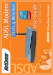
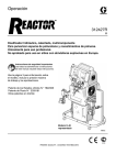
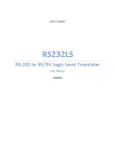
Contents
Important Information ............................................................................................................................................... 3
What you should know about Power Over Ethernet (PoE) .................................................................. 3
Introduction .............................................................................................................................................................. 4
Package Contents ................................................................................................................................ 4
Installation ................................................................................................................................................................ 5
The POE Injector ................................................................................................................................
Injector .........................................................................................................................................
The POE Splitter .................................................................................................................................
Splitter .........................................................................................................................................
Connecting the Power-over-Ethernet Adapter Kit ................................................................................
5
5
6
6
7
Appendix A: Cable Connections ........................................................................................................................... 10
RJ-45 Ethernet Network Ports ................................................................................................... 10
Appendix B: Troubleshooting ............................................................................................................................... 12
Appendix C: Technical Specifications .................................................................................................................. 13
Appendix D: Registering your NetComm Product ................................................................................................ 14
Contact Information .......................................................................................................................... 14
Legal & Regulatory Information ........................................................................................................ 14
Product Warranty .............................................................................................................................. 15
NetComm NPPOE1001 Power over Ethernet Kit
2
YML720Rev1
www.netcomm.com.au
Important Information
What you should know about Power Over Ethernet (PoE)
Power-over-Ethernet (PoE) or "Active Ethernet" eliminates the need to run 240 Volt power to
Wireless Access Points and other devices on a wired LAN. Using Power-over-Ethernet systems,
installers need to run only a single CAT5 Ethernet cable that carries both power and data to each
device. This allows greater flexibility in the locating of AP's and network devices and significantly
decreasing installation costs in many cases. The placement of a Network device can be up to 328
feet (100 meters) away by using standard category 5 Ethernet cable.
Power-over-Ethernet begins with a CAT5 "Injector" that inserts a DC Voltage onto the CAT5 cable.
The Injector is typically installed in the "wiring closet" near the Ethernet switch or hub.
Some Wireless Access Points and other network accept the injected DC power directly from the
CAT5 cable through their RJ45 jack. These devices are considered to be "PoE-Compatible" or
"Active Ethernet Compatible".
Devices that are not "PoE Compatible" can be converted to Power-over-Ethernet by way of a DC
"Picker" or "Tap". These are sometimes called Active Ethernet "Splitters". This device picks-off the
DC Voltage that has been injected into the CAT5 cable by the Injector and makes it available to the
equipment through the regular DC power jack.
WARNING:
Never connect the Injector - Power Over Ethernet Out directly to a network
device such as a Hub, Switch, IP Camera or Print Server unless you are
ABSOLUTELY sure the device and network is PoE Compatible. Additionally,
make sure your PoE compatible device or network is designed to handle
the 48 volts DC delivered by the PoE injector. If you do not check the POE
compatibility and voltage required, you will damage the attached device, the
Injector and any computer connected to the network. NetComm will not
accept any responsibility for any loss or damage araising from the use of
this product in the wrong manner.
PLEASE ENSURE THAT YOU COMPLETLY READ THE FOLLOWING
INSTRUCTIONS AND COMPLY WITH THEM BEFORE CONNECTING ANY
DEVICE OR POWER.
By proceeding to use this product you agree that you have read these instructions carefully and
accept this disclaimer. Any damage to the product due to a failure to follow the instructions in this
guide will void the warranty.
YML720 Rev1
www.netcomm.com.au
NetComm NPPOE1001 Power over Ethernet Kit
3
Introduction
Thank you for purchasing NetComm’s Power-over-Ethernet Adapter Kit. Before you start installing
the Power-over-Ethernet Adapter Kit, verify the following parts are included in your package.
Package Contents
The package contains the following:
■ One unit Power-over-Ethernet Injector, and one
unit of Power-over-Ethernet Splitter
■ One DC Power Adapter
■ One AC Power Cord
■ A Quick Installation Guide and Package
Contents Note.
If you do not have any of the items listed above, please contact your local distributors or authorized
resellers of the manufacturer.
NetComm NPPOE1001 Power over Ethernet Kit
4
YML720Rev1
www.netcomm.com.au
Installation
This chapter describes the function of the Power-over-Ethernet Adapter Kit and shows how to install
it on your network.
Basic knowledge of networking is assumed. Read this chapter before you proceed.
The POE Injector
The PoE Injector mixes data and power into the RJ-45 connector and then transmits power and data
over the Cat5 cable to the PoE (direct connection) compatible device or PoE Splitter. This Injector
inputs 48 Volts DC into the PoE system.
Figure 1 Injector
Object
Description
Injector
PWR LED
Lights green to indicate that the power has been supplied
to the device
Power and Data Out Port
Connects the RJ-45 port of Splitter through Cat 5
Ethernet cable
DC Jack
Connects to the power adapter for receiving power - 48
Volts DC.
Cat 5 Ethernet Cable
Connects to other network devices
YML720 Rev1
www.netcomm.com.au
NetComm NPPOE1001 Power over Ethernet Kit
5
The POE Splitter
PoE Splitters split data and power from the Cat5 Ethernet line. It will output Ethernet data to the
device via the Etherent port and DC 5V/1.67A or 12V/1A power via the DC output cable.
Figure 2 Splitter
Object
Description
Splitter
PWR LED
Lights green to indicate that the power has been supplied
to the device
Power and Data In Port
Connects the RJ-45 port of Injector through Cat 5
Ethernet cable
Cat 5 Ethernet Cable
Connects to other network devices
Power Cable
Connects to other DC jack on the network device
Voltage Selector
Used to select DC 5V/1.67A or 12V/1A power
NetComm NPPOE1001 Power over Ethernet Kit
6
YML720Rev1
www.netcomm.com.au
Connecting the Power-over-Ethernet Adapter Kit
The Power-over-Ethernet Adapter Kit does not need software configuration. To install it, simply
complete the following steps. Figure 2.4 shows how the Power-over-Ethernet Adapter Kit is
connected to your wireless network.
Step 1
Select a location for your Power-over-Ethernet Adapter Kit. Put it on a
sturdy desktop. Keep enough ventilation space between the device and the
surrounding objects.
Step 2
Connect the DC power adapter to the Injector and plug the DC power
adapter into a power socket. Do NOT turn the power ON at this stage.
Step 3
Connect the Injector's built RJ-45 Cat 5 Ethernet cable to your network.
Step 4
Connect the RJ-45 Cat 5 Ethernet cable to the Injector's Power & Data Out
port. Connect the other end of the Ethernet cable to the Splitter's Power &
Data In port.
Step 5
Connect the Splitter's RJ-45 Cat 5 Ethernet cable to your networking device.
Connect the Splitter's power cable to the other power port on networking
device.
Step 6
Select the voltage output on the splitter, either 5Volts or 12Volts. Please
check the voltage required by your device in your device manual.
Step 7
Turn the power on to the injector at the 240Volt Power Point.
Figure 3
YML720 Rev1
www.netcomm.com.au
NetComm NPPOE1001 Power over Ethernet Kit
7
Now you should see that power is provided to the device you have connected to the POE Splitter. If
there is no power, please refer to the Troubleshooting section in this guide.
The following figure illustrates connection of an NP5400 Access Point using Power Over Ethernet.
Figure 4
Please Note: The total distance from the NB1300+4 ADSL Modem/Router to the NP5400
Access Point (as used in this example) should be less than 100 metres (i.e.
328 feet).
NetComm NPPOE1001 Power over Ethernet Kit
8
YML720Rev1
www.netcomm.com.au
The following figure illustrates the connection of a Network Camera using Power Over Ethernet.
Figure 5
Please Note: The total distance from the NB1300+4 ADSL Modem/Router to the Network
Camera (as used in this example) should be less than 100 metres (i.e. 328
feet).
YML720 Rev1
www.netcomm.com.au
NetComm NPPOE1001 Power over Ethernet Kit
9
Appendix A: Cable Connections
This cable information is provided for your reference only. Please ensure you only connect the
appropriate cable into the correct socket on either this product or your computer.
If you are unsure about which cable to use or which socket to connect it to, please refer to the
hardware installation section in this manual. If you are still not sure about cable connections, please
contact a professional computer technician or NetComm for further advice.
RJ-45 Ethernet Network Ports
RJ-45 Network Ports can connect any networking devices that use a standard LAN interface, such as
a Hub/Switch Hub or Router. Use unshielded twisted-pair (UTP) or shield twisted-pair (STP) cable
to connect the networking device to the RJ-45 Ethernet port. Depending on the type of connection,
10Mbps or 100Mbps, use the following Ethernet cable, as prescribed.
RJ-45 plug
attached to cable
Caution:
Please do not use telephone cables. Telephone cables do not support
Ethernet or Fast Ethernet
Ethernet Type
Cable Requirements
Maximum Length
10BASE-T
Category 3 or better, UTP or STP
100 metres
100BASE-TX
Category 5 or better, UTP or STP
100 metres
Twisted-pair cabling comes in various grades, or categories. Category 5 is required for Fast Ethernet,
and is also the most reliable and most commonly used category. You can buy UTP Category 5
(Unshielded Twisted Pair) Ethernet cabling in precrimped lengths, or you can crimp your own.
Crimping your own can result in faulty connections if the RJ-45 tips are not attached properly.
Precrimped Category 5 cabling is available at most computer retail stores.
The most reliable and commonly used type of Category 5 cabling used is UTP, or "unshielded
twisted pair." STP, or "shielded twisted pair" wiring is only necessary for network environments
exposed to excessive amounts of electromagnetic interference, or EMI. These environments include
areas with high sources of electrical power, air conditioning, generators, and radio signals.
STP is also used for wiring outdoors.
There are two types of the wiring: Straight-Through Cables and Crossover Cables. Category 5 UTP/
STP cable has eight wires inside the sheath. The wires form four pairs. Straight-Through Cables has
same pinouts at both ends while Crossover Cables has a different pin arrangement at each end.
NetComm NPPOE1001 Power over Ethernet Kit
10
YML720Rev1
www.netcomm.com.au
In a straight-through cable, wires 1,2,3,4,5,6,7 and 8 at one end of the cable are still wires 1~8 at the
other end. In a crossover cable, the wires of 1,2,3,6 are reversed so that wire 1 become 3 at the other
end of the cable, 2 becomes 6, and so forth.
To determine which wire is wire 1, hold the RJ-45 cable tip with the spring clip facing towards the
ground and the end pointing away from you. The copper wires exposed upwards to your view. The
first wire on the far left is wire 1. You can also refer to the illustrations and charts of the internal
wiring on the following page.
Straight-Through Cabling
Wire
Becomes
1
1
2
2
3
3
6
6
Cross-Over Cabling
Note:
Wire
Becomes
1
3
2
6
3
1
6
2
To prevent loss of signal, make sure that the length of any twisted-pair
connection does not exceed 100 metres.
RJ-45 Connector
Pin Assignment
1
2
3
6
4,5,7,8
YML720 Rev1
www.netcomm.com.au
Normal Assignment
Input Receive Data +
Input Receive Data Output Transmit Data +
Output Transmit Data Power - PoE pins
NetComm NPPOE1001 Power over Ethernet Kit
11
Appendix B: Troubleshooting
The LEDs do not light up.
Check that the power supply is properly connected.
The Injector LED does not light up.
First, refer to the installation instructions to ensure that you have connected the cables correctly.
Secondly, ensure you are using straight-through category 5 cable. The cable must be an 8-wire
cable. A 4-wire cable will not work. Look at the connector to see if it has 8 wires. Refer to the
Appendix on Cable connections for more information.
Both injector and splitter LEDs light up, but the access point still does not get any
power.
Check the following:
1. You are using the correct DC power cable and it is plugged in.
2. The access point is a working unit. Plug in the power plug, which was provided in the access
point’s original packaging and verify that there is power to the access point.
What if I connect the wrong cable and connectors?
If using a Category 5 Ethernet cable in a pure 10/100 Base-T environment, there will be no harm.
Note: Do not use this product in a Gigabit or 10-Gigabit Ethernet network environment.
The NPPOE1001 does work with my Gigabit Ethernet network.
This product is designed specifically for a 10/100 Base-T environment. Using it with a Gigabit
Ethernet device may damage the device and void the product warranty.
My network device still does not work.
If you have followed the above tips and your device (i.e. Access Point, Network Camera, etc) is still
not working, please refer to the troubleshooting section of your device’s manual.
NetComm NPPOE1001 Power over Ethernet Kit
12
YML720Rev1
www.netcomm.com.au
Appendix C: Technical Specifications
Standards
IEEE 802.3, IEEE 802.3u, IEEE 802.3x,
Protocol
CSMA/CD
Ports
1 * 10/100Mbps RJ-45 port (per unit)
Connector
RJ-45
Speed
10/100Mbps at half/full duplex
Cable Type
UTP/STP Category 5 or better
LED
Power
Environmental Information
Dimensions (WxHxD)
Adapter Kit: 89 x 47 x 30 (mm)
Unit Weight
Injector: 64g Splitter: 87g
PSE Adapter: 64g
Operating Temperature
0°C to 40°C (32°F to 122°F)
Storage Temperature
-55°C to 105°C (-67°F to 221°F)
Operating Humidity
10% to 90% relative humidity, non-condensing
Storage Humidity
20% to 95% relative humidity, non-condensing
Power
DC 48V
Standard Conformance
EMC Certification
YML720 Rev1
www.netcomm.com.au
FCC Class B, CE, C-Tick (N367)
NetComm NPPOE1001 Power over Ethernet Kit
13
Appendix D: Registering your NetComm Product
All NetComm Limited (“NetComm”) products have a standard 12 month warranty from date of
purchase against defects in manufacturing and that the products will operate in accordance with the
specifications outlined in the User Guide. However some products have an extended warranty
option (please refer to packaging). To be eligible for the extended warranty you must supply the
requested warranty information to NetComm within 30 days of the original purchase by registering
on-line via the NetComm web site at:
www.netcomm.com.au
Contact Information
If you have any technical difficulties with your product, please do not hesitate to contact
NetComm’s Customer Support Department.
Email:
[email protected]
Fax:
(+612) 9424-2010
Web:
www.netcomm.com.au
Legal & Regulatory Information
This manual is copyright. Apart from any fair dealing for the purposes of private study, research, criticism or review, as permitted under
the Copyright Act, no part may be reproduced, stored in a retrieval system or transmitted in any form, by any means, be it electronic,
mechanical, recording or otherwise, without the prior written permission of NetComm Limited. NetComm Limited accepts no liability or
responsibility, for consequences arising from the use of this product.
NetComm Limited reserves the right to change the specifications and operating details of this product without notice.
NetComm is a registered trademark of NetComm Limited.
All other trademarks are acknowledged the property of their respective owners.
Customer Information
ACA (Australian Communications Authority) requires you to be aware of the following information and warnings:
(1)
This unit shall be connected to the Telecommunication Network through a line cord which neets the requirements of the ACA TS008
Standard.
(2)
This equipment has been tested and found to comply with the Standards for C-Tick and or A-Tick as set by the ACA . These
standards are designed to provide reasonable protection against harmful interference in a residential installation. This equipment
generates, uses, and can radiate radio noise and, if not installed and used in accordance with the instructions detailed within this
manual, may cause interference to radio communications. However, there is no guarantee that interference will not occur with the
installation of this product in your home or office. If this equipment does cause some degree of interference to radio or television
reception, which can be determined by turning the equipment off and on, we encourage the user to try to correct the interference by
one or more of the following measures:
(3)
•
Change the dirtection or relocate the receiving antenna.
•
Increase the separation between this equipment and the receiver.
•
Connect the equipment to an alternate power outlet on a different power circuit from that to which the receiver/TV is connected.
•
Consult an experienced radio/TV technician for help.
The power supply that is provided with this unit is only intented for use with this product. Do not use this power supply with any other
product or do not use any other power supply that is not approved for use with this product by NetComm. Failure to do so may cause
damage to this product, fire or result in personal injury.
NetComm NPPOE1001 Power over Ethernet Kit
14
YML720Rev1
www.netcomm.com.au
Product Warranty
The warranty is granted on the following conditions:
1.
This warranty extends to the original purchaser (you) and is not transferable;
2.
This warranty shall not apply to software programs, batteries, power supplies, cables or other accessories supplied
in or with the product;
3.
The customer complies with all of the terms of any relevant agreement with NetComm and any other reasonable
requirements of NetComm including producing such evidence of purchase as NetComm may require;
4.
The cost of transporting product to and from NetComm's nominated premises is your responsibility; and,
5.
NetComm does not have any liability or responsibility under this warranty where any cost, loss, injury or damage of
any kind, whether direct, indirect, consequential, incidental or otherwise arises out of events beyond NetComm's
reasonable control. This includes but is not limited to: acts of God, war, riot, embargoes, acts of civil or military
authorities, fire, floods, electricity outages, lightning, power surges, or shortages of materials or labour.
6.
The customer is responsible for the security of their computer and network at all times. Security features may be
disabled within the factory default settings. NetComm recommends that you enable these features to enhance your
security.
The warranty is automatically voided if:
1.
You, or someone else, use the product, or attempts to use it, other than as specified by NetComm;
2.
The fault or defect in your product is the result of a voltage surge subjected to the product either by the way of
power supply or communication line, whether caused by thunderstorm activity or any other cause(s);
3.
The fault is the result of accidental damage or damage in transit, including but not limited to liquid spillage;
4.
Your product has been used for any purposes other than that for which it is sold, or in any way other than in strict
accordance with the user manual supplied;
5.
Your product has been repaired or modified or attempted to be repaired or modified, other than by a qualified
person at a service centre authorised by NetComm; and,
6.
The serial number has been defaced or altered in any way or if the serial number plate has been removed.
Limitations of Warranty
The Trade Practices Act 1974 and corresponding State and Territory Fair Trading Acts or legalisation of another
Government ("the relevant acts") in certain circumstances imply mandatory conditions and warranties which cannot be
excluded. This warranty is in addition to and not in replacement for such conditions and warranties.
To the extent permitted by the Relevant Acts, in relation to your product and any other materials provided with the product
("the Goods") the liability of NetComm under the Relevant Acts is limited at the option of NetComm to:
■
Replacement of the Goods; or
■
Repair of the Goods; or
■
Payment of the cost of replacing the Goods; or
■
Payment of the cost of having the Goods repaired.
All NetComm ACN 002 490 486 products have a standard 12 months warranty from date of purchase. However some
products have an extended warranty option (refer to packaging). To be eligible for the extended warranty you must supply
the requested warranty information to NetComm within 30 days of the original purchase by registering on-line via the
NetComm web site at www.netcomm.com.au.
NetComm reserves the right to request proof of purchase upon any warranty claim.
YML720 Rev1
www.netcomm.com.au
NetComm NPPOE1001 Power over Ethernet Kit
15
Technical Specifications
Standards
IEEE 802.3, IEEE 802.3u, IEEE 802.3x,
Protocol
CSMA/CD
Ports
1 * 10/100Mbps RJ-45 port (per unit)
Connector
RJ-45
Speed
10/100Mbps at half/full duplex
Cable Type
UTP/STP Category 5 or better
LED
Power
Environmental Information
Dimensions (WxHxD)
Unit Weight
Adapter Kit: 89 x 47 x 30 (mm)
Injector: 64g Splitter: 87g
PSE Adapter: 64g
Operating Temperature
0°C to 40°C (32°F to 122°F)
Storage Temperature
-55°C to 105°C (-67°F to 221°F)
Operating Humidity
10% to 90% relative humidity, non-condensing
Storage Humidity
20% to 95% relative humidity, non-condensing
Power
DC 48V
Standard Conformance
EMC Certification
FCC Class B, CE, C-Tick (N367)
NetComm is Australia’s dynamic data communications and networking solutions
provider. For more information on this and other NetComm products, please visit
www.netcomm.com.au
NetComm Limited ABN 85 002 490 486
PO Box 1200, Lane Cove NSW 2066 Australia.
Phone (02) 9424 2070 • Fax (02) 9424 2010
www.netcomm.com.au • Email [email protected]
Trademarks and registered trademarks are the property of NetComm Limited or their
respective owners. Specifications are subject to change without notice. Images
shown may vary slightly from the product.