1
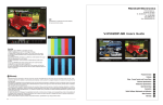
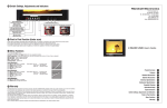
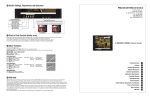
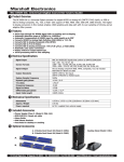
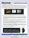
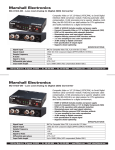
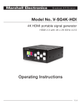
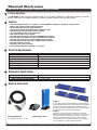
Marshall Electronics
MC-0105 Distribution Amplifier Users Guide
71 Product Overview
The MC-0105 is used to convert Composite Video or Y/C (S-Video) (NTSC/PAL) to VGA. When placed in line with a
monitor cable there is an added capability to switch the display between video and VGA signals.
72 Features
73
Converts Composite Video or Y/C (Svideo ) to VGA (RGBHV) for display on projectors or data screens
NTSC or PAL operation with automatic detection
Illuminated power and input signal indicators
Transforms interlaced 525/625 images to Progressive Scan
Adaptive filtering removes NTSC interlace artifacts
2x over sampling for true color reproduction
VGA output processed as 4:4:4/RGB
Automatically scales NTSC 4:3 input to 640x480 Pixel resolution
Automatically scales NTSC 16:9 input to 720x480 Pixel resolution
Automatically scales Pal 4:3 input to 640x576 Pixel resolution
Automatically scales Pal 16:9 input to 720x576 Pixel resolution
Automatic Gamma correction
Automatic color space conversion
Switch between VGA and composite or Y/C inputs
Electrical Specifications
Signal Input
Signal Output
Sample Frequency
K factor
Signal to Noise
Dynamic gain/phase
Cable length
Power required
74
HD-15 VGA, Composite Video BNC 75Ω, Y/C Video 4 pin Mini- din
HD-15 VGA (27 Mhz for NTSC)
27mhz
<1%
>42 db
<1% / <1.50
Up to 350ft (100m) AGC compensated
6V D.C. supplied from external supply (Model V-PS6-1.2A)
Mechanical Specifications
Dimensions
Weight
V-PS6-1.2A Power Supply Weight
4.75”W x 3.75”D x 1.0”H
0.55 lbs (0.25kg)
0.20 lbs (0.10kg)
75 Optional Accessories
Cable: RGB-5HD15-X
(X = Length in feet 6, 10, 15, 20)
V-CB1 Desktop Stand
V-CRM-2
2U (1.75” tall) Conversion and Distribution 3 Module Bracket.Up
to three Marshall Electronics 4.75” wide conversion or distribution
modules can be securely installed into a standard EIA 19 inch
rack with the V-CRM-3 mounting bracket. Every V-CRM-3 includes
two blank panels for a clean cosmetic appearance.
V-CRM-3
Single RU (1.75” tall) Conversion and Distribution 2 Module
Bracket.Two Marshall Electronics 7.72” wide or one 7.72” plus one
4.75” wide conversion or distribution modules can be securely
installed into a standard EIA 19 inch rack with the V-CRM-2
mounting bracket. Every V-CRM-3 includes one blank panel and
one 4.75” adapter for a clean cosmetic appearance.
1910 East Maple Ave. El Segundo, CA 90245 • Tel.: 800-800-6608 • Fax:310-333-0688 • www.LCDRacks.com • Email: [email protected]
76 Operational Setup
1. Unpack the MC-0105, and accompanying V-PS6-1.2A power supply and physically inspect for any damage that may have occurred
during shipping. Also verify there is a small package with mounting accessories. Should there be any damage, immediately contact
Marshall Electronics at 800-800-6608. If you are not located within the continental united states call +1 310-333-0606.
2. Install in your desired location. If wall mounting is required, attach the mounting brackets by removing the Phillips head screws on
the sides, closest to the rear of the unit. (See below) Only one screw per side should be removed. Use the same screw to attach the
bracket with the flange facing away from the side and parallel to the front of the MC-0105 metal case. The flange has two holes. For
desktop use, apply the supplied rubber pads.
3. Connect required cables for signal input and output.
All BNC connectors should be rated for 75Ω.
4. Plug the V-PS6-1.2A power supply into the A.C. source
5. Attach twist lock power connection from V-PS6-1.2A
power supply to the back of the unit.
6. Turn on the MC-0105 by depressing the power
switch located on the front of the unit.
77 Switch Settings and Indicators
Power On/Off switch with System indicator.
Illuminates Red when Power is connected.
Illuminates Green when the MC-0105 is switched on
Input Selection
Indicators
Input Selection Toggle Switch
Toggles input source to output selection
78 Input Connectors
Analog
Video In
BNC
S-Video In
4 Pin Din (Female)
Pin1 - GND
Pin2 - GND
Pin3 – Y in
Pin4 – C in
VGA-In
DB HD-15 Female
Connector Input
Pin-1 Red In
Pin-2 Green In
Pin-3 Blue In
Pin-4
Pin-5
Pin-6 Ground
Pin-7 Ground
Pin-8 Ground
Pin-9
Pin-10
Pin-11
Pin-12
Pin-13 VS In
Pin-14 HS In
Pin-15
VGA-Out
DB HD-15 Female
Connector Output
Pin-1 Red Out
Pin-2 Green Out
Pin-3 Blue Out
Pin-4
Pin-5
Pin-6 Ground
Pin-7 Ground
Pin-8 Ground
Pin-9
Pin-10
Pin-11
Pin-12
Pin-13 VS Out
Pin-14 HS Out
Pin-15
6 VDC from
V-PS6-1.2A power
supply
Left Pin - Pos
Right Pin- Neg
Note: VGA inputs signals of any format will be output as the same format when VGA source is selected.
For best operation a multi-sync monitor should be used.
Note: NTSC signals are converted to 480x640 VGA resolution output. PAL signals are converted to 576x640 VGA resolution output.
1910 East Maple Ave. El Segundo, CA 90245 • Tel.: 800-800-6608 • Fax:310-333-0688 • www.LCDRacks.com • Email: [email protected]