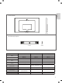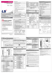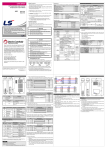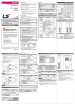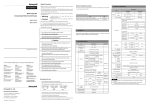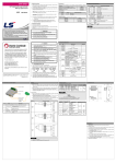
1
OWNER’S MANUAL
Canvas Speaker
Please read the safety information carefully before using the product.
OCF100
*MFL68001401*
P/NO : MFL68001401 (1311-REV00)
www.lg.com
ACCESSORIES
2
VESA Guide Paper
Installation Guide Tape
4 EA
Owner's Manual
Optical Cable
Guide Spacer (Top)
2 EA
Guide Spacer (Bottom)
2 EA
Guide Spacer (Top)
Fixing Screw
2 EA (M6 X L26)
Guide Spacer (Bottom)
Fixing Screw
2 EA (M4 X L20)
Safety Clip (Top)
2 EA
Safety Clip (Bottom)
2 EA
Safety Clip Fixing Screw
(Top/Bottom)
4 EA (M4 x 12)
Protection Cushion (Upper)
2 EA (Thickness: 11 mm)
Protection Cushion (Bottom)
2 EA (Thickness: 1.5 mm)
Wall Mounting Anchor
8 EA
Wall Mounting Screw
8 EA
Rubber
2 EA (Thickness: 12 mm)
SAFETY PRECAUTIONS
ENGLISH
- If you are a professional installer, please read this manual carefully before installing the product.
- After installing the product according to the manual, ensure that the user also reads the manual carefully.
After reading the manual, please keep it handy for future reference.
Warning
The product should be installed by a qualified professional
specified by the retail store.
The product should be installed where its weight can be fully
supported.
When moving or replacing the product after installation,
contact a qualified installer specified by the retail store.
Be sure not to hang the power cable and signal cable on the
back of TV when installing the wall-mounted TV.
Product installation by non-qualified personnel is very dangerous and may
cause personal injury.
Installation or movement of the product must be carried out by a skilled
professional. If an unqualified person moves and installs the product, it may
cause safety risks.
If the product is installed on a weak surface, the product may fall, causing
injury.
Damaged cables may result in fire, electric shock, or damage to the product.
Do not hang on this product or apply any shock to it.
The product may fall and cause injury.
Caution
Follow the instructions in the manual to properly install this
product.
To install or adjust the height of the product, two or more
people are needed.
When installing the product, first check that the wall is
strong enough and use the anchors and screws provided.
When drilling holes into the wall, make sure you use a drill
and drill bit with the specified diameter. Ensure that you also
follow the instructions regarding the depth of the holes.
If you do not follow the instructions, the product may be installed incorrectly
and cause serious injury or damage to the product.
Otherwise, they may not bear the weight of the product, which could cause a
safety hazard.
If you try to install or move the product alone, it may fall, causing injury or
damage to the product.
Otherwise, the product may be installed incorrectly and cause safety issues.
Do not clean the product with wet towels and do not place a
heater or humidifier underneath it.
Keep this product away from sprinklers, sensors, hightension wires, and power sources. Do not install it in a
location where vibrations or impact shocks are likely to
occur.
Make sure that the power cord is removed from the outlet
before installing the product.
Wear safety gloves when installing the product. Do not use
your bare hands.
Moisture, steam, or heat permeating into the product may result in fire,
electric shock, or product damage.
Otherwise, it may cause an electric shock or fire.
Otherwise, it may cause personal injury.
Be sure to use the accessory cable provided. Otherwise, it
may cause damage to the connector from friction between
the product and the wall.
3
Before Installation
* Do not use this product for purposes other than to attach the TV to the wall.
* Be careful when installing and using the wall-mounted TV to prevent product damage and safety hazards.
* If the instructions in the manual are unclear, stop the installation and contact the service center. If you are still having problems understanding
the instructions after contacting the service center, seek a professional to install the product for you.
* An individual with experience in mechanical and architectural fields may not have any difficulty understanding this manual or installing the
product, even if they are not a professional.
* This product is designed to be mounted onto walls with a standard amount of space between the studs. LG Electronics is not responsible for
any issues resulting from the product being mounted on walls that do not have the appropriate amount of space.
* Install the wall mounting screws to the wall in the center of the studs at both ends. It is recommended to use the stud finder, which is optional
and not included with this product.
* When installing the bracket on a concrete wall, or on any other walls capable of holding the strength specified in the manual, you may remove
the brackets for mounting the product onto the wall with studs that have the standard amount of space and then follow the instructions for
attaching the brackets to make the installation easier.
* Only install the bracket on vertical walls. Do not install the bracket on an angled wall or on the ceiling. LG Electronics is not liable for problems
that occur as a result of installing the product on a slanted wall or on the ceiling.
* Check that the accessories provided with the product are all included before installing. LG Electronics is not liable for any damage or loss of
the accessories after the package has been opened.
* Make sure that the accessories are kept out of the reach of children to prevent safety hazards, such as choking from swallowing any small
parts.
* Make sure that the screws are tight. Applying excessive force to screws may damage to the wall, affect the product performance, or cause it
to become damaged.
* Make sure that the installed TV does not exceed the specified tension load and that no external force is applied to it.
* In order to prevent any accidents, take care when handling tools during the installation.
Tools for Installation
Philips screwdriver, 8 mm spanner, drill, and Ф 8 mm drill bit for concrete walls, Ф 4 mm drill bit for wood or steel, level, stud finder, and slotted
screwdriver.
Installation
1
Attaching the Guide Spacer to the TV
- If the screws are not fully tightened when you fix the guide spacers, check the length of the screws and refer to the technical service
manual.
Guide Spacer (Top) Fixing Screw
Guide Spacer (Top)
Guide Spacer (Bottom) Fixing Screw
Guide Spacer (Bottom)
How to attach the Guide Spacers
1. Remove any screws that have been installed into the mounting holes.
2. Fix the guide spacers and the guide spacer screws in order as illustrated.
- Place the TV on a table with the screen facing down. Make sure that you place it on a flat surface covered with a soft cloth or cushion to
protect it from scratches.
- Tighten the screw until the TV, the guide spacers, and the screws are attached securely.
- Use a Philips screwdriver (manual or drill) to tighten the screws.
4
2 Attaching the Protective Cushion
ENGLISH
-A
ttach the protective cushion to minimize the impact between the TV and the canvas speaker in case they bump against each
other when adjusting the angle. Attach the protective cushion to the back corners of the TV as shown in the illustration.
- The thickness of upper cushion (2 EA) is 11 mm, and the bottom cushion (2 EA) is 1.5 mm.
Protection Cushion (Upper), 2 EA (Thickness: 11 mm)
Protection Cushion (Bottom), 2 EA (Thickness: 1.5 mm)
Marking the Screw Fixing Spots on the Wall Using the VESA Guide
3 Paper
1430 mm
840 mm
(VESA guide sheet size)
865 mm
(Actual product size)
1. Check the VESA standard for the TV.
2. Mark the wall mounting location using the VESA guide paper provided.
3. Remove the VESA guide sheet after marking the wall mounting location.
* Please note that the VESA guide sheet is shorter than the actual product by 12.4 mm at the top and bottom, respectively.
5
4 Fixing the Anchors and Screws
Please follow the instructions.
- Check the wall material and thickness of the finish.
- You can use the anchors and screws provided with the TV for walls made with concrete, lightweight concrete, soft fieldstone, hard
fieldstone, brick, or cellular blocks.
- Do not mount the device on walls made with plaster board or medium-density fiberboard (MDF). In this case, the anchor and screws must
be inserted into the concrete behind the finish. If there is no concrete on the other side, then you must install a separate hanger first to fix
the anchors and screws to.
- When installing it on a wall not specified in this manual, make sure each mounting position can withstand an load of 70 kgf (686 N) and a
shearing load of 100 kgf (980 N) or more.
Anchor
a
b
c
Wall Mounting Screw
d
e
- Use Ф 8 mm drill bit for concrete and a hammer (impact) drill.
a. Drill a hole with a depth of 80-100 mm, where the anchor will be attached to, using an 8 mm drill bit.
b. Clean out the drilled hole.
c. Insert the provided anchor into the hole. (Use a hammer when inserting the anchor.)
d. Place the wall mounting bracket close to the wall. Place the angle adjusting attachment facing upward.
e. Insert the wall mounting screw into the hole and tighten it.
Tighten the screw using a recommended torque of 45 kgf/cm - 60 kgf/cm or more.
5 Installing the Wall Mounting Supporter
Attach the screws
→ Tighten the 4 wall mounting screws.
→ If either of the mounting locations is inappropriate for
installation, move both of the brackets to the locations
that meet the conditions above.
→ Fix the wall mounting supporter using the wall mounting
screws as shown in the illustration.
→ Tighten the screws until the wall, the wall mounting
supporter, and the screws are joined together securely
using a Phillips screwdriver (manual or drill) or 8 mm
spanner.
Wall mounting screw, 4 EA
6
ENGLISH
How to attach Rubber Accessories
Where to attach rubber accessories
→ Use stiffening material when attaching the product to a wall type not specified in this manual.
→ Attach the two rubber accessories to the area on the bottom of the Canvas Speaker back panel as shown in the figure.
CAUTION
This method of attaching rubber accessories is only applicable when attaching the product to a wall not specified in this manual.
yy
You are advised to attach the Canvas Speaker to a concrete wall.
yy
7
6
Assembling the Wall Mounting Supporter and the Canvas Speaker
- Two or more people are needed to install the product.
Installation Guide Tape
1. Place the Canvas Speaker on the wall mounting supporter attached to the wall in the direction of the arrows.
- Attach the guide tape above the left and right holes of the wall mounting supporter and the left and right guide spacers of the Canvas
Speaker.
- Attach the guide tape side by side, as shown in the illustration, and then install the product. When the installation is complete, remove the
guide tape.
- Make sure that the product is fixed securely by lightly pulling on the upper part of the Canvas Speaker.
- If the product is not level after the installation, make it level by moving the Canvas Speaker left and right.
Wall Mounting Screw
2. Install the wall mounting bracket using the wall mounting screws.
8
Safety Clip (Top) Fixing screw
ENGLISH
Safety Clip (Top)
Safety clip inserted between
the wall mounting bracket and
the product
3. Hang the TV with the guide spacers on the bracket wall, as illustrated with the arrow. Attach the lower part first, then attach the upper
part by slightly lifting up the TV.
4. Insert the provided safety pin, which prevents product displacement, in the direction of the arrow, while adjusting the position, and then
completely fix the safety clip with the fixing screw for the safety clip. If the safety pin is not fixed, as shown in the illustration, the product
may fall.
→ Make sure that the product is fixed securely by lightly pulling on the bottom of the TV.
When using cables and accessories to install the product, other than the accessories provided, make sure the product is installed at a
sufficient distance from the wall to prevent any stress on the connected cables and accessories.
→ Pushing on the product with excessive force may cause damage to the product.
9
7
10
Adjusting the Level of the Product
If the product is not level after the installation, adjust it using the screw.
(The product goes up or down according to the rotation direction of the screw.)
8 Organizing the Power Cord
ENGLISH
After pulling the canvas speaker forward and draw out the power cord through the square hole below the canvas speaker to organize it.
Square hole
below the
canvas speaker
TV Power cord
Back
Front
Side
11
ew,
9 Fix the Safety Clip (Bottom)
- Be sure to fix the safety clip (bottom) after organizing the power cord. Fix the safety clip (bottom), using the safety clip fixing screw,
into the wall mounting bracket square hole as shown in the illustration.
- Fix the clip to make it bilaterally symmetrical.
- Make sure that the product is fixed securely by lightly pulling on the upper part of the Canvas Speaker.
- Pull out the lower part of the canvas speaker to check if the product is securely fixed.
Safety Clip Fixing screw
Safety Clip (Bottom)
Combined Appearance of the wall
mounting brackets, canvas speaker,
and Safety Clip
Canvas Speaker
10 Connect the Optical Cable
Optical Cable
The optical cable connected to the Canvas Speaker
12
The optical cable connected to the TV
ENGLISH
11 Assembled Appearance of the Canvas Speaker and the TV
Canvas Speaker
TV
CAUTION
Do not place the TV near or on
yy
sources of heat, as this may result in
fire or other damage.
Leave a 10 cm (4 inches) (minimum)
yy
space
from the wall for proper ventilation.
10 cm (4 inches)
10 cm
10 cm
10 cm
13
SPECIFICATIONS
° ~ °± °
[Unit: mm]
Wall Mounting bracket
° ~ °± °
° ~ °± °
Max.
° ~ °± °
Min.
° ~ °± °
° ~ °± °
° ~ °± °
145
14
° ~ °± °
145
145
145
ENGLISH
Canvas Speaker
<Front>
<Side>
Wall Mounting Supporter
<Front>
Model Name
Width
Height
Depth
<Side>
Canvas Speaker
Wall Mounting bracket
1430 (mm)
450 (mm)
Wall Mounting Supporter
500 (mm)
56.2 (inches)
17.7 (inches)
19.6 (inches)
865 (mm)
500 (mm)
64 (mm)
34.0 (inches)
19.6 (inches)
2.5 (inches)
64 (mm)
40 (mm)
9 (mm)
2.5 (inches)
1.5 (inches)
0.3 (inches)
17.7 (kg)
5.7 (kg)
0.6 (kg)
39.0 (lbs)
12.5 (lbs)
1.3 (lbs)
-
210 (Top) / 364 (Bottom) * 450
-
Max. Tensile Load
-
50 (kgf)
50 (kgf)
Audio Output
100 W
-
-
Power Sources
AC 100V~240V 50~60Hz
(SMPS ADPATER)
-
-
Weight
Wall Mounting VESA
Specifications
Input
SPDIF input
-
-
Front, Woofer
Impedance : 8 Ω
-
-
15
The model name and serial number are
located on the back and a side of the
product. Please make a note of these below.
MODEL
SERIAL