Transcript
Menu [SHUTTER] - SHUTTER AUTO
Design and specifications are
subject to change without notice.
Menu [SHUTTER] - FIXED Mode Setup
1) SHUTTER setup (for LENS MANUAL)
Operation Manual
ll
t
m
7
8. OPERATING CAMERA
12
4. COMPOSITION
8
9. SPECIFICATIONS
36
Water and Moisture.
5. INSTALLATION
9
10. TROUBLESHOOTING
38
Do not use this product near water or moisture.
(For example. near a bathtub, wash bowl, kitchen
sink, or laundry tub, in a wet basement, or near a
swimming pool,etc)
4
2. PRECAUTIONS
16
RETURN
5
Avoid installing in a humid or dusty place.
Avoid installing in places where there are
strong magnetic fields and electric signals.
Never expose the camera to rain and water.
Do not point the camera at the sun. This could
damage the camera whether it is operating or not.
Do not install the camera where the temperature
could exceed the allowable range.
7
4. COMPOSITION
Ceiling
3 Draw out power / video wires to the connecting places.
Guide Pattern
the 3-axis camera bracket by hand.
COLOR DOME CAMERA
Dome Base
Change setting using LEF T, RIGHT button.
AUTO
B/W
COL
OR.
2) AUTO
P ress MENU in RETURN to return
to the previous screen.
END LEVEL
074
9
5
• ON
SHUTTER
• AUTO
• FLK
• FIXED
• MANUAL
WHITE BAL.
• ATW
• AWB
• FIXED
• MANUAL
FUNCTION
• BLC
• AGC
LANGUAGE
• CONTRAST
• SHARPNESS
• CB_GAIN
• CR_GAIN
• ENGLISH
• KOREAN
• PRIVACY
• MOTION
DOWN
S E TU P
CAMERA ID
SHUTTER
WHITE BAL.
FUNCTION
ADJUST
LANGUAGE
RESET
EXIT
J601
J102
• GAMMA
04
J6
• CHINESE1 • CHINESE2 • JAPANESE
J613
RESET
J611
EXIT
UP SW1
LEFT
RIGHT
Service Monitor Connecter:
Use service monitor
connector to set camera angle
& focus when installing.
COLOR DOME CAMERA
COLOR DOME CAMERA
Lef t and Right side is switched
as shown on the picture.
4. Select "Exit" and then press the MENU button
COLOR DOME CAMERA
to finish the SETUP (Save and Exit)
ENGLISH
P ress MENU key in CAMERA ID.
I D SETUP
Character is changed each time UP , DOWN is
pressed. (Can select up to 63 letters)
CAMERA ID
P ress MENU button in
to
exit from ID setup mode
P ress MENU button in 'C' to correct and erase
the chosen entry.
A
_
In ON
2) AREA
C
POSITION
Use LEF T, RIGHT button
to adjust GAMMA value.
(USER 0.05 0.10 0.15 ~ 1.0)
, press MENU button. (see p.31)
Set motion sensitivity 0(MAX)~255(MIN)
2) POSITION setup. Press POSITION
P ress Menu button to confirm selection of the character.
15
4) MOTION TRACE setup
ON : Display motion detection AREA .
!
30
COLOR DOME CAMERA
COLOR DOME CAMERA
COLOR DOME CAMERA
FUNCT IO N
BLC
AGC
DAY NIGHT
PRIVACY
MIRROR
GAMMA
MOTION
RETURN
OFF
ON
AUTO
OFF
OFF
0.45
OFF
Setting value can be adjusted
using LEFT or RIGHT button.
29
31
Menu [FUNCTION] - MOTION AREA 1
1) MOTION AREA setup
F UN CTI ON
BLC
AGC
DAY NIGHT
PRIVACY
MIRROR
GAMMA
MOTION
RETURN
OFF
ON
AUTO
OFF
OFF
0.45
OFF
3) MOTION TH. Setup
RETURN
P ress Return to go to previous screen. ID is displayed by pressing EXIT on MAIN MENU.
setup
In AREA
Move the character using UP , DOWN, LEFT, RIGHT button.
14
, press MENU button.
Display MOTION details.
COLOR DOME CAMERA
3. Set details using LEFT, RIGHT button.
OFF
AUTO
ATW
In FUNCTION MODE,
use UP, DOWN button to select GAMMA.
OFF
ON
AUTO
OFF
OFF
0.45
OFF
ON
DEF AULT value OFF
COLOR DOME CAMERA
2. Select OSD item using UP, DOWN button.
SE T U P
CAMERA ID
SHUTTER
WHITE BAL.
FUNCTION
ADJUST
LANGUAGE
RESET
EXIT
BLC
AGC
DAY NIGHT
PRIVACY
MIRROR
GAMMA
MOTION
RETURN
1) MOTION DETECTION setup
P ress MENU key in ON
state.
(Access ID setting MODE)
• MAIN SETUP menu is displayed on the monitor.
F UN CTI ON
Menu [FUNCTION] - MOTION
1) CAMERA ID setup (default setting OFF)
1. Press MENU button, then SETUP mode is activated.
27
28
Main Menu - CAMERA ID
Main Menu - SETUP
AREA 0
ON
017
058
020
055
001
Menu [FUNCTION] - GAMMA
OFF
13
AREA SEL
AREA STATE
LEFT
RIGHT
TOP
BOTTOM
COLOR
RETURN
1) GAMMA setup (DEFAULT 0.45)
MIRROR default setting OFF
ON setting - Use LEFT, RIGHT button.
ENGLISH
ON
ON
AUTO
ON
OFF
0.45
OFF
PRIVACY
COLOR - Change entire color of the AREA (16 COLOR)
OFF
AUTO
ATW
DOWN
12
Select AREA SEL - PRIV ACY 0~3.
26
• Select the status using the
joystick. (up, down, left, right)
BLC
AGC
DAY NIGHT
PRIVACY
MIRROR
GAMMA
MOTION
RETURN
2) PRIVACY details setup
BOTTOM - Change bottom portion of each AREA size.
- Push and hold MENU button 1 second
to access the setup mode.
MENU(SET):
SET BY JOY STICK
RIGHT
UTP1
COLOR DOME CAMERA
ADJUST
• DAY NIGHT
• MIRROR
LEFT
ON
TOP - Change top por tion of each AREA size.
SETUP
• OFF
UP SW1
BURST
Menu [FUNCTION] - MIRROR
COLOR DOME CAMERA
CAMERA ID
P ress MENU button.
Details of each area is dsplayed.
1) MIRROR setup
Push the Joy stick for one second, and the OSD
appears on the screen. Move the Joy Stick up, down,
left & right to control the OSD functions.
SETUP MENU
DAY N I GHT B/W
RIGHT - Change right por tion of each AREA size.
Setting up the Menu
!
Af ter ON
mode setup, 4 AREA groups are
configured as displayed on the right-side picture.
LEF T - Change left portion of each AREA size.
11
8. OPERATING CAMERA
FUNCT IO N
Default setting OFF - Use LEF T,RIGHT button.
Change setup to ON
mode.
AREA ST ATE - 0~3 AREA ON/OFF
Tilt rotation: Adjusting the vertical angle.
Pan rotation: Adjusting the horizontal angle.
Horizontal rotation: Adjusting the horizontal position of the screen.
Focus handle: Focus (Far or Near)
Zoom handle: Zoom (Tele or Wide)
IR LED(4mm~9mm): 850nm / 30(20EA), P ower Consumption(4.5W)
Sensor
10
3-Axis
1) PRIVACY setup
Af ter setup, return to the previous screen
by pressing MENU button.
Camera Lay-out
COLOR DOME CAMERA
12VDC (10V~15V), 360mA (Max)
Initial value setup is recommended.
Menu [FUNCTION] - PRIVACY
Use LEF T, RIGHT button
to set BURST ON / OFF.
J603
COLOR DOME CAMERA
1.0 Vp-p
Red
!
RETURN
setting
Move to screen on the right side.
2
Remark
NIGHT --> DAY conversion illumination intensity setup 0~255 (DEFAULT : 12 Lux)
0 : High illumination intensity, 255 : Low illumination intensity
mode setup
P ress MENU in B/W
3
1
2
3
4
5
6
7
END LEVEL
25
1) B/W
1
power source.
Initial value setup is recommended.
01
Menu [FUNCTION] - DAY NIGHT 3
7
Power- 12VDC
(Red)
!
DAY N I GHT AUT O
24
7. NAME AND FUNCTIONS
GND
Yellow
DAY --> NIGHT conversion illumination intensity setup 0~255 (DEFAULT : 4 Lux)
0 : High illumination intensity, 255 : Low illumination intensity
092
6
#2 Power Input
ST ART LEVEL
START LEVEL
4
#1 Video Output
DAY --> NIGHT or NIGHT --> DAY conversion time setup
0 : No DAY NIGHT AUTO conversion
1~63 : Can set from 1 second to 15 seconds
Adjust value using LEF T / RIGHT button.
Dome Cover
Insert coin to the side hole and
remove the dome cover by twist coin.
Terminal Color
setup mode.
DEL AY
OFF
ON
AUTO
OFF
OFF
0.45
OFF
7 Fix the dome cover on the base by covering.
NOTE
• Use 12V DC
mode setup
P ress MENU button in AUTO
BLC
AGC
DAY NIGHT
PRIVACY
MIRROR
GAMMA
MOTION
RETURN
DELAY
8
095
1) DAY NIGHT OSD description
F UN CTI ON
Select item using UP / DOWN button.
Video Output
AGC GAIN
Menu [FUNCTION] - DAY NIGHT 2
Move to screen on the right side.
Service Monitor Cable
Video
(Yellow)
Use LEF T, RIGHT button
to adjust AGC GAIN value (0~255)
0:MIN , 255:MAX
23
6 Put the dome cover over the base.
3-Axis
AG C CO NT RO L
:RETURN
Guide Pattern
Mounting
Screw
5 Adjust desired focus and scene by turning and moving
Mounting Screw
RETURN
Move to DA Y NIGHT screen on the right side.
4 Fixed the camera to a celling using four screws.
Operation Manual
16
BLC RATIO
1) DAY NIGHT setup
Drill four holes according to the guide pattern then
insert anchors into the drilled holes.
2
BLC AREA
P ress MENU button in ON
to display the screen on the right side.
Menu [FUNCTION] - DAY NIGHT 1
1 Stick the guide pattern on the wall or ceiling.
0 ~ 255 (Level Adjustable)
Sharpness
0 ~ 31 (Level Adjustable)
0.1 Lux(30IRE, AGC ON), 0 Lux(IR LED)
Applicable Lens
Manual Lens
Manual Vari-focal (f=4~9mm)
Supply Voltage
12VDC (10V~15V)
1/60 ~ 100,000
Power Consumption
Operating Temperature
1/50 ~ 100,000
Language
English / Korean / Chinese 1 / Chinese 2 / Japanese
10. TROUBLESHOOTING
Max. 4.5W / 360mA
39
-20~+60
Dome Size (Ø)
100 mm
Weight
3-Axis
37
-10~+50(Recommendation: -5~+40)
Storage Temperature
ATW (1,800 K~10,500 K) / AWB / Fixed / Manual
ON / OFF
Problem
BLC SETUP
22
5. INSTALLATION
3-Axis
6. CONNECTION
COLOR DOME CAMERA
Installation and storage
ON / OFF (64 Programmable Zone)
Contrast
Approx. 366g
. Memo
If you have trouble operating your camera, refer to the following table.
If the guidelines do not enable you to solve the problem, contact an authorized technician.
1) AGC setup
P ress MENU button to return
to the previous screen.
• Privacy Zone Selectable (4 Programmable Zone)
• Motion Detection Selectable (64 Programmable Zone)
• Sharpness Enhanced Adjustable
• Flickerless Selectable
• Gamma Enhanced Selectable
• BLC Zone Selectable (64 Programmable Zone)
Avoid installing in places where the camera
would be subject to strong vibrations.
Motion Detection
Camera ID
3-Axis
User / 0.5 ~ 1.0 Adjustable
AGC default setting ON
P ress MENU button in RETURN
to move to FUNCTION MODE.
High Performance Menus For Functions
COLOR DOME CAMERA
When attaching or removing the lens, handle
with care in order to that moisture and dust do
not enter the camera.
OSD (On Screen Display)
36
ON / OFF (Horizontal)
Gamma
Manual
White Balance
ON / OFF (4 Programmable Zone)
Mirror
Internal Sync
Focus
Electronic Shutter
BW / Color / Auto
Privacy
500(H) x 582(V)
380 TV Lines
Lens
ON / OFF (Level Adjustable)
Day & Night
Composite: 1.0Vp-p, 75, Unbalanced
Horizontal Resolution
Menu [FUNCTION] - AGC
Use LEF T, RIGHT button
to change BLC LEVEL value (0~63)
0:MIN , 63:MAX
Day & Night (Programmable)
COLOR DOME CAMERA
Do not drop the camera or subject it to shocks
and vibrations to avoid possible damage.
COLOR DOME CAMERA
Min. Illumination (F1.2, 30 IRE) : 0.1 Lux (Color)
0.0 Lux (IR LED On)
Be sure the ambient temperature is less than
40 in installation intended for long ter m
continuous operation.
510(H) x 492(V)
EXET
21
BLC, AGC
2:1 Interlace Transfer 1/3 Inch Super HAD CCD
Min. Illumination (F1.2)
Menu [FUNCTION] - BLC 3
COLOR DOME CAMERA
Do not disassemble the camera and never touch
parts inside the camera.
PAL
More than 50dB (AGC OFF)
20
Use UP , DOWN button
to move to BLC RATIO.
HD61X
NTSC
Luminance S/N Ratio
P ress MENU button for more than 1 second
to move to BLC AREA MODE.
High Sensitivity 1/3 Inch Sony Super HAD CCD
Handling
HD61
RETURN
EXIT - Save AREA and retur n to
BLC SETUP MODE.
1) BLC RATIO setup (BLC LEVEL value setup)
MODEL
Sync. System
ALL SET
RETURN - R eturn to BLC AREA setup mode.
Set or release BLC AREA
using MENU button.
YES
NO
orean Chinese1 Chinese 2 Japanese
Signal System
Video Output
ALL CLEAR
ALL SET - Set all 64 BLC AREA
LOA D DE FA ULT
9. SPECIFICATIONS
Effective Pixels
BLC AREA
ALL CLEAR - Clear all set AREA
ENGLISH
ENGLISH
35
Image Sensor
2) BLC OSD description
setup
Use UP , DOWN, LEFT, RIGHT button
to move the AREA setup position.
Power source
This product should be operated only from the type
of power source indicated on the marking label.
If you are not sure of the type of power supplied to
your home, consult your dealer or local power
company.
Exit from BLC AREA MODE
to move to BLC SETUP MODE screen.
BLC AREA
Select YES to reset your camera
to default factory condition
34
1) BLC AREA MODE
BLC SETUP
ENGLISH K
3-Axis
Menu [FUNCTION] - BLC 2
BLC RATIO
2) BLC AREA
!
Select YES or NO .
OFF
AUTO
ATW
COLOR DOME CAMERA
19
COLOR DOME CAMERA
255
COLOR DOME CAMERA
COLOR DOME CAMERA
BLUE
18
3. FEATURES
3-Axis
113
OFF
AUTO
ATW
S E TUP
CAMERA ID
SHUTTER
WHITE BAL.
FUNCTION
ADJUST
LANGUAGE
RESET
EXIT
COLOR DOME CAMERA
3. FEATURES
4) Click "Return" to go to MAIN SETUP
RED
Use UP , DOWN, LEFT, RIGHT button
to move AREA setting position.
Use MENU button to set and release AREA .
P ress MENU button for more than 1 second
to move to MOTION AREA MODE
2) MOTION AREA MODE
MOTI ON
Y ou will return to MOTION AREA MODE
after "Exit" from MOTION AREA MODE.
AREA
MOTION TH.
037
MOTION TRACE
OFF
MO T IO N AREA
ALL CLEAR
ALL SET
RETURN
EXET
RETURN
COLOR DOME CAMERA
11
3) Set details using LEFT, RIGHT button.
SET UP
CAMERA ID
SHUTTER
WHITE BAL.
FUNCTION
ADJUST
LANGUAGE
RESET
EXIT
Choose the language mode you
wish to operate in.
COLOR DOME CAMERA
7. NAME AND FUNCTIONS
Cleaning
:RETURN
OFF
ON
AUTO
OFF
OFF
0.45
OFF
Select RESET .
Press MENU button.
The screen on the bottom appears.
COLOR DOME CAMERA
Do not place this product on an unstable cart, stand,
or table. The product may fall causing serious injury
to a child or adult, and damage to the product.
Use only with a cart or stand recommended by the
manufacturer, or sold with the product.
Mounting should follow the manufacturer's instructions,
and should use a mounting accessory recommended
by manufacturer.
Af ter selecting LANGUAGE,
change setting using LEFT or RIGHT button.
COLOR DOME CAMERA
Read all of the safety and operating instructions
before using the product.
Save this instructions for later use.
10
BLC
AGC
DAY NIGHT
PRIVACY
MIRROR
GAMMA
MOTION
RETURN
33
1) RESET
DEF AULT value - ENGLISH
:RETURN
P ress MENU button in BLC ON
,
to display the screen on the right side.
COLOR DOME CAMERA
6. CONNECTIONS
6
Function
205
Main Menu - RESET
1) LANGUAGE setup
AWB FIXED : MODE 1
1) BLC SETUP MODE
Installation
Unplug this appliance from wall outlet before
cleaning. Do not use liquid cleaners or aerosol
cleaners. Use a damp cloth for cleaning.
No.
CB_GAIN
Adjust COL OR CR_GAIN value (0~255)
32
setup
Menu [FUNCTION] - BLC 1
Read Instructions
Retain Instructions
• The wire is polarized.
190
5) CR_GAIN setup
FUNCT IO N
AWB MANUAL
P ress MENU button in RETURN
to exit from setup mode.
1. SAFETY INSTRUCTIONS
COLOR DOME CAMERA
Before using this camera, please read this operation manual carefully to obtain
the best result and keep this manual for future reference.
COLOR DOME CAMERA
This installation should be made by a qualified service person and should abide to all local codes.
3-Axis
setup
As shown on the lower right picture,
set Red and Blue color value temperature.
CAUTION - To prevent electric shock and risk of fire hazards:
Do NOT use power sources except for that specified.
Do NOT expose this appliance to rain or moisture.
Thank you for purchasing this COLOR VIDEO CAMERA.
#2
12
CB_GAIN
Adjust COL OR CB_GAIN value (0~255)
P ress MENU button in FUNTION
to show the OSD display on the right.
COLOR DOME CAMERA
s
. Contents
setup
Can set from MODE 1 to MODE 4.
3
#1
SHARPNESS
RETURN
Main Menu - LANGUAGE
COLOR DOME CAMERA
2) FIXED
3) MANUAL
2
AWB F I X ED
2) Select item using UP, DOWN button.
The manufacturer could void the user's authority to operate the equipment.
"WARNING-TO PREVENT FIRE OR SHOCK HAZARD, DO NOT EXPOSE THE UNIT TO RAIN OR MOISTURE"
1) FUNCTION
In WHITE BAL., press LEF T, RIGHT button
to select the mode you wish to operate
ATW A
WB FIXED
MANU
AL .
THE GRAPHIC SYMBOLS WITH SUPPLEMENTAL MARKING ARE ON THE BOTTOM OF THE SYSTEM.
3-Axis
2) CONTRAST setup
083
4) CB_GAIN setup
Main Menu - FUNCTION
1) WHITE BALANCE setup
WARNING
The exclamation point within an equilateral triangle is intended to
alert the user to the presence of important operating and maintenance(servicing) instructions in the literature accompanying the appliance.
5
17
COLOR DOME CAMERA
akes adju
The lightning flash with arrowhead symbol, within an equilateral
triangle, is intended to alert the user to the presence of un-insulated
"dangerous voltage" within the product's enclosure that may be of
sufficient magnitude to constitute a risk of electric shock to persons.
COLOR DOME CAMERA
16
This equipment has been tested and found to comply with limits for a Class A digital device, pursuant to part 15
of the FCC Rules.
These limits are designed to provide reasonable protection against harmful interference when the equipment is
operated in a commercial environment.
This equipment generates, uses, and can radiate radio frequency energy and, if not installed and used in accordance
with the instruction manual, may cause harmful interference to radio communications.
Operation of this equipment in a residential area is likely to cause harmful interference in which case the user will be
required to correct the interference at their own expense.
Explanation of two Symbols
COLOR DOME CAMERA
www.honeywellvideo.com
INFORMATION
CAUTION! TO REDUCE THE RISK OF ELECTRIC SHOCK, DO NOT REMOVE COVER (OR BACK).
NO USER-SERVICEABLE PARTS INSIDE. REFER SERVICING TO QUALIFIED SERVICE PERSONNEL.
3-Axis
EXIT - Save AREA and retur n to MOTION SETUP MODE.
A DJUS T
CONTRAST
Each LEVEL value can be
adjusted using LEFT, RIGHT button.
3) SHARPNESS setup
Menu [WHITE BAL.] - WHITE BALANCE Mode Setup
RISK OF ELECTRIC SHOCK
DO NOT OPEN
6
:RETURN
COLOR DOME CAMERA
READ AND KEEP THIS
OPERATION MANUAL
C AU T I O N
3-Axis
!
RETURN - R eturn to MOTION AREA Setup Mode.
056
BRIGHTNESS
Move to screen on the right side.
ALL SET - Set all 64 MOTION AREA .
SHUTTER M : 1/60
P ress LEFT or RIGHT button in SHUTTER.
Can be set in ([NTSC: 1/60 ~ 1/100,000]
[PAL: 1/50 ~ 1/100,000]) range.
P ress MENU button in ADJUST.
Adjust aper ture value (0~31)
. User Information
2. PRECAUTIONS
SHUT TER AUT O
1) ADJUST setup
ALL CLEAR - R elease all set AREA
:RETURN
www.honeywellvideo.com
1. SAFETY INSTRUCTIONS
SHUT T ER FIXED
Adjust Y -gain value (0~255)
Need Help?
Call 1.800.796.CCTV for sales, service and customer support.
3-Axis
Setting Mode : AUTO
1) MOTION OSD description
setup
P ress MENU button in FIXED
to display the screen on the right side.
ke
tm
en
is brac
t e a s y.
Ax
!
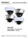
Color Dome Camera
1) FIXED
COLOR DOME CAMERA
p
P ress LEFT or RIGHT button in SHUTTER
to select the mode to
AUTO
FLK FIXED
MANU
AL .
COLOR DOME CAMERA
m
to inst
a
le
3-
Si
HD61 Series
3-Axis
Main Menu - ADJUST
Menu [FUNCTION] - MOTION AREA 2
P/N:3810-0148B Rev 0 07/04
38
Solutions
Nothing appears on the
screen.
• Check that the power cord and line connection between the camera and monitor
are fixed properly.
• Check that you have properly connected VIDEO cable to the camera VIDEO output jack.
The image on the screen
is dim.
• Is lens stained with dirt? Clean your lens with soft, clean cloth.
• Set the monitor to proper condition.
• If the camera is exposed to too strong light, change the camera position.
• Adjust the lens' focus properly.
The image on the screen
is dark.
• Adjust the contrast feature of the monitor.
• If you have an intermediate device, set the 75/ Hi-z properly .
• Adjust DC Level, on the OSD menu.
The camera is not working
properly, and the surface
of the camera is hot.
• Check that you have properly connected the camera to an appropriate power source.
The image on the screen
flickers.
• Is the camera facing to direct sunlight or fluoresent lighting?
Change the camera position.
