1
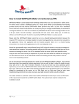
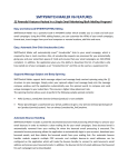
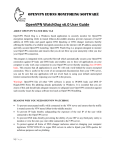
Exabyte Field Instruction
March 2002
Installing or Replacing a Tape Drive
in an Exabyte 430 or 215 Library
Contents
1
Preparing for installation . . . . . . . . . . . . . . . . . 2
2
Removing the tape drive. . . . . . . . . . . . . . . . . . 4
3
Removing the drive’s service access cover . . . 5
4
Installing the tape drive . . . . . . . . . . . . . . . . . . 6
5
Connecting the cables (SCSI library) . . . . . . . . 7
6
Connecting the cables (Fibre Channel library) 8
7
Testing the library and resuming operation . . 9
1005911-003
#1005911-003#
Copyright
Copyright 2002 by Exabyte Corporation. All rights reserved. This item and the information contained
herein are the property of Exabyte Corporation. No part of this document may be reproduced,
transmitted, transcribed, stored in a retrieval system, or translated into any language or computer
language in any form or by any means, electronic, mechanical, magnetic, optical, chemical, manual, or
otherwise, without the express written permission of Exabyte Corporation, 1685 38th Street, Boulder,
Colorado 80301.
Trademark Notices
Exabyte and Exapak are registered trademarks; M2, MammothTape, SmartClean, EZ17 and NetStorM
are trademarks; People Working for You and SupportSuite are servicemarks of Exabyte Corporation.
Advanced Intelligent Tape (AIT) is a trademark of Sony Electronics, Inc. All other product names are
trademarks or registered trademarks of their respective owners.
Revision History
1
000
August 2000
Initial release
001
November 2000
Added 215M information
002
April 2001
Added AIT information
003
March 2002
Added Fibre Channel M2 information for 430M-FC
Preparing for installation
These instructions describe how to install or replace a tape drive in the
following Exabyte® libraries:
! 430M and 215M SCSI libraries with M2 tape drives
! 430A and 215A SCSI libraries with AIT tape drives
! 430M-FC Fibre Channel library with M2 tape drives
The tape drive kit contains one Exabyte Mammoth-2 (M2™) or one AIT tape
drive, pre-installed in a drive carrier. The M2 tape drive has either a SCSI or
Fibre Channel interface. The AIT tape drive has a SCSI interface. The SCSI
tape drive kit includes one wide SCSI cable. The Fibre Channel tape drive
kit includes one optical fiber cable.
➤ Important
The Fibre Channel M2 tape drive kit is for
the 430M-FC library only. Do not install a Fibre Channel
M2 in the 215M.
Note: You can convert a 430M library from SCSI to Fibre Channel
(430M-FC) using an upgrade kit available from Exabyte. Contact
Exabyte at 1-800-774-7172 or 1-800-392-8273 for this kit.
Page 2 of 12
1005911
1 Preparing for installation
Installing or replacing a tape drive in the 430 or 215 library involves the
following steps:
! Removing an existing tape drive or drive service access cover
! Installing the new tape drive
! Testing the library and resuming operation
Note: The illustrations in these instructions show the 430 SCSI library. The
component locations are similar in the 215 library. Where necessary,
the 430M-FC is also shown.
To prepare for installation:
1. Obtain a #2 Phillips screwdriver.
2. Ensure that the environment is free of conditions that could cause
electrostatic discharge (ESD). If possible, use an antistatic mat and
grounded static protection wristband during installation. If a mat and
wristband are not available, touch a known grounded surface, such as
the computer’s metal chassis.
CAUTION
If the library is attached to a SCSI bus, make sure the
library is not communicating across the bus before
powering it off. Powering off the library may disrupt
communication on the SCSI bus.
3. Power off the library and disconnect the power cord.
WARNING!
Before continuing with these procedures, be sure that
the library’s power switch is in the off position and
that the power cord is disconnected from the library.
March 2002
Page 3 of 12
2 Removing the tape drive
2
Removing the tape drive
If you are replacing an existing tape drive, follow the steps below to remove
the drive. If you are installing an additional tape drive, skip to Section 3,
“Removing the drive’s service access cover,” on page 5.
1. From the library’s back panel, disconnect the cables from the back of the
tape drive you plan to replace. If you are replacing a SCSI tape drive,
remove any terminator that might be installed on the drive.
SCSI Library
Tape drive
SCSI connectors
Fibre Channel Library
Tape drive
Fibre Channel
connector
2. Use a #2 Phillips screwdriver to release the two captive screws that
secure the tape drive carrier to the library.
Handle
Captive screws
Page 4 of 12
1005911
3 Removing the drive’s service access cover
3. Remove the drive carrier by grasping the handle and pulling it straight
out of the library. The drive carrier weighs about 5 pounds; make sure
you support the bottom of the carrier as you remove it.
3
Removing the drive’s service access cover
Follow these steps if you are installing a tape drive in an empty slot.
1. From the back panel, use a #2 Phillips screwdriver to release the two
captive screws that secure the service access cover to the library.
Captive screws
2. When the screws are loosened, remove the drive access cover.
March 2002
Page 5 of 12
4 Installing the tape drive
4
Installing the tape drive
CAUTION
Do not install a mixture of Fibre Channel and SCSI tape
drives in the library. Mixing drive interfaces could
cause data loss.
1. Insert the tape drive so that the handle is at the top and the fan is at the
bottom, as shown in the following figure. The drive should slide easily
toward the front of the library.
2. Tighten the captive screws on each end of the drive carrier to
8.0 inch-pounds (9.2 kg-cm) of torque.
Page 6 of 12
1005911
5 Connecting the cables (SCSI library)
5
Connecting the cables (SCSI library)
For the 430M, 430A, 215M, and 215A SCSI libraries, connect the SCSI cables
as described in this section. For the 430M-FC Fibre Channel library, go to
Section 6, “Connecting the cables (Fibre Channel library),” on page 8.
CAUTION
To avoid damaging the tape drive, make sure the
library is powered off when you connect it to the SCSI
bus.
1. If you replaced a tape drive, reconnect the SCSI cables (or cable and
terminator) to the new tape drive as they were before. If you installed
an additional tape drive that will be on the same SCSI bus as the other
drives in the library, remove the terminator from the adjacent drive and
install it on the new drive. Then, use the SCSI cable provided in the kit
to connect the new tape drive to the adjacent drive. The following
figure is an example of a typical cable and terminator configuration for
three tape drives on a single SCSI bus.
Jumper cables
Library
SCSI connectors
Terminator
SCSI cable
(to host)
Tape drive
SCSI connectors
2. Reconnect the power cord and power on the library. The library
automatically calibrates the position of the new tape drive.
3. If you installed a new tape drive, set the SCSI ID for the drive as
described in Exabyte 430M and 430A Libraries Installation and Operation or
Exabyte 215M and 215A Libraries Installation and Operation. If you
replaced a drive, the new drive automatically assumes the SCSI ID of
the old tape drive.
4. Proceed to Section 7, “Testing the library and resuming operation,” on
page 9.
March 2002
Page 7 of 12
6 Connecting the cables (Fibre Channel library)
6
Connecting the cables (Fibre Channel library)
For the Fibre Channel 430M-FC, connect the optical fiber cable as follows:
1. Remove the protective plug from the optical fiber connector on the new
tape drive, if present.
2. Attach an optical cable from the Fibre Channel hub or switch to the Fibre
Channel connector on the new tape drive, as shown in the following
figure.
Note:
You can use the optical cable provided in the kit, or you can use
your own cable. Make sure that the cable is compatible with
the GBIC on the tape drive and on the hub or switch.
Tape drive
optical fiber
connector
3. Reconnect the power cord to the library, then power on the library. The
library automatically calibrates the position of the new tape drive.
Page 8 of 12
1005911
7 Testing the library and resuming operation
7
Testing the library and resuming operation
Before resuming operation, use the Demo Menu from the operator panel to
ensure that the robot and the newly installed tape drive are
communicating correctly. The Demo Menu causes the robot to randomly
move cartridges from slot to slot, including the fixed cartridge slots.
To test the library operation using the Demo Menu, follow these steps:
1. Insert a cartridge in the entry/exit port.
Note:
All other cartridges in the library can remain where they are.
The testing can also be performed without any cartridges other
than the one in the entry/exit port.
2. If necessary, disable security as follows:
a. Press the [MENU] key to display the menus. Press the down arrow key
until “Security” appears on the screen, as shown below. If security
is enabled, “LCD Password” appears on this screen.
!S e c u r i t y
L CD
P a s s w o r d
b. Press [ENTER]. The following screen appears.
P a s s w o r d ?
0 0 0
↕
c. Use the left and right arrow keys to move across the columns. Enter
your password using the up and down arrow keys to select a
number. Press [ENTER]. Security is then disabled.
3. Change the control mode to LCD as follows:
a. Press [MENU] to display the menus, then press the down arrow key
until “Robot Mode” appears. The Robot Mode screen shows the
currently activated mode.
!R o b o t
Mo d e
SCS I
March 2002
Page 9 of 12
7 Testing the library and resuming operation
b. Press [ENTER]. An informational message appears, then the following
screen appears.
R o b o t
Mo d e ?
SCS I
↕
c. Use the arrow keys to select LCD mode and press [ENTER]. The screen
shows the new selection.
4. From the operator panel keypad, press [MENU] to display the menus.
Press the down arrow key until “Demo Menu” appears, as shown below.
!D e m o
Me n u
5. Press [ENTER]. The following screen appears.
U s e
D r i v e N↑
6. Press the up arrow to display “Y.” Press [ENTER]. The following screen
appears.
0 0 0 0 0 1 0
←
↕
→
7. Use the arrow keys to set the number of moves (the left and right arrow
keys move across the columns; the up and down arrow keys change the
numbers). Then press [ENTER].
Note: The default number of moves is 10. Exabyte recommends that
you perform at least 20 moves.
8. The library begins the demo and displays status messages. If you want
to abort a demo in progress, press [ESCAPE].
9. After the demo moves have successfully completed, press [STATUS] to
return to the main menu.
10. Return the control mode to SCSI by pressing [MENU] then pressing the
down arrow key until “Robot Mode” appears.
!R o b o t
Mo d e
L CD
Page 10 of 12
1005911
7 Testing the library and resuming operation
11. Press [ENTER] and use the arrow keys to select SCSI mode. Press [ENTER]
again.
If the library does not operate correctly, check the following:
SCSI library
Fibre Channel library
# Are the devices on each SCSI bus attached to
# Are the GBICs and cables used to connect the
the library all LVD?
tape drives to the Fibre Channel loop
compatible?
# Are the SCSI buses terminated?
# Are the Fibre Channel cables firmly connected
# Are the SCSI cables firmly connected to the
library, tape drives, and host computer?
# Are the SCSI IDs unique for the devices on each
SCSI bus?
to the library, tape drives, and the Fibre Channel
hub or switch?
# Is the library operating in the correct control
mode? (For most applications, the control
mode should be set to SCSI.)
# Is the library operating in the correct control
mode? (For most applications, the control
mode should be set to SCSI.)
If you cannot solve the problem yourself, contact your service provider or
Exabyte Technical Support (1-800-445-7736 or 1-303-417-7792).
March 2002
Page 11 of 12
7 Testing the library and resuming operation
Notes
Page 12 of 12
1005911