1
Bulletin 74.2:Y695A
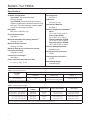
Specifications
Available Configurations
Flow Capacities
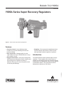
Type Y695A: Direct-operated vapor
recovery regulator.
Type Y695AM: Direct-operated vapor recovery regulator equipped with a blocked throat and O-ring stem seal. The lower diaphragm casing is tapped 1/2 NPT for control line connection.
See Table 4
Orifice Size
7/16-inch (11 mm)
Construction Materials
See Table 3
Body Sizes
Material Temperature Capabilities(1)
Nitrile:
-20° to 180°F (-29° to 82°C)
Fluorocarbon (FKM):
40° to 300°F (4° to 149°C)
Perfluoroelastomer (FFKM):
-20° to 300°F (-29° to 149°C)
Ethylenepropylene (EPDM):
-20° to 300°F (-29° to 149°C)
NPS 3/4 or 1 (DN 20 or 25)
End Connection Styles
See Table 1
Maximum Allowable Inlet (Casing) Pressure(1)
150 psig (10,3 bar)
Maximum Outlet Pressure(1)
150 psig (10,3 bar)
Maximum Emergency Inlet Pressure to Avoid
Internal Parts Damage
150 psig (10,3 bar)
Adjusting Screw
Spring Case Vent Connection
1/4 NPT
Diaphragm Case Connection
See Table 2
Flow Coefficients with Fully Open Disk
Control Pressure Ranges(1)
Pressure Setting Adjustment
Cg: 120, CV: 3.43, C1: 35
1/2 NPT
Approximate Weight
19 pounds (9 kg)
1. The pressure/temperature limits in this bulletin and any applicable standard or code limitation should not be exceeded.
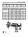
Table 1. End Connection Styles
END CONNECTION STYLES(1)
BODY SIZES,
NPS (DN)
Ductile Iron
CF8M
Stainless Steel
Hastelloy® C
3/4 or 1 (20 or 25)
NPT
NPT, ANSI Class 150 RF,
ANSI Class 300 RF, or PN 16/25/40
ANSI Class 150 RF
1. All flanges have 14-inches (356 mm) face-to-face.
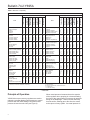
Table 2. Control Pressure Ranges
SPRING PART
NUMBER
SPRING COLOR
SPRING WIRE DIAMETER
2 to 7-inches w.c. (5 to 17 mbar)(1)(2)
3 to 13-inches w.c. (7 to 32 mbar)(1)(2)
10 to 26-inches w.c. (25 to 65 mbar)
1B653827052
1B653927022
1B537027052
Red
Olive drab
Yellow
0.085-inch (2,2 mm)
0.105-inch (2,7 mm)
0.114-inch (2,9 mm)
3.625-inches (92,1 mm)
3.75-inches (95,2 mm)
4.188-inches (106 mm)
0.9 to 2.5 psig (0,06 to 0,17 bar)
1.3 to 4.5 psig (0,09 to 0,31 bar)
3.8 to 7 psig (0,26 to 0,48 bar)
1B537127022
1B537227022
1B537327052
Light green
Light blue
Black
0.156-inch (4,0 mm)
0.187-inch (4,8 mm)
0.218-inch (5,5 mm)
4.060-inches (103 mm)
3.938-inches (100 mm)
3.980-inches (101 mm)
RELIEF SET PRESSURE RANGE
1. Spring ranges based on spring case installed pointed down. When installed pointing up, the spring ranges increase by 2-inches w.c. (5 mbar).
2. Do not use Fluorocarbon (FKM) diaphragm with these springs at diaphragm temperatures lower than 60°F (16°C).
2
FREE LENGTH