1
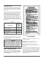
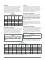
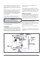
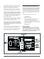
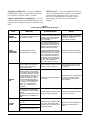
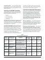
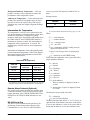
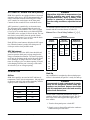
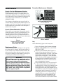
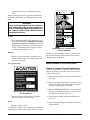
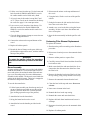
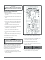
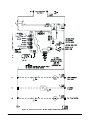
Installation, Operating and Maintenance Manual PYRAMID 8000® SERIES COMPRESSED BREATHING AIR PURIFIERS WARNING Improper use of this equipment may cause illness, injury or death. This instruction manual must be read by everyone who installs or works with this equipment. Bulletin 289 Rev. F (10/99) Copyright ©1999 Flair-New Castle, Inc. Printed in USA Table of Contents SAFETY INSTRUCTIONS . . . . . . . . . . . . . . . . . . . . . . . . . . . . 1 SAFETY . . . . . . . . . . . . . . . . . . . . . . . . . . . . . . . . . . . . . . . 2 INSTALLATION . . . . . . . . Receiving and Inspection . . Clearance . . . . . . . . . . Ambient Air Temperature. . Location . . . . . . . . . . . Air Compressor Equipment . Air Piping and Connections . Drain Piping . . . . . . . . . Electrical Connections . . . . . . . . . . . . . . . . . . . . . . . . . . . . . . . . . . . . . . . . . . . . . . . . . . . . . . . . . . . . . . . . . . . . . . . . . . . . . . . . . . . . . . . . . . . . . . . . . . . . . . . . . . . . . . . . . . . . . . . . . . . . . . . . . . . . . . . . . . . . . . . . . . . . . . . . . . . . . . . . . . . . . . . . . . . . . . . . . . . . . . . . . . . . . . . . . . . . . . . . . . . . . . . . . . . . . . . . . . . . . . . . . . . . . . . . . . . . . 2 2 3 3 3 3 3 4 4 PURIFICATION PROCESS. . . . . . . . . . . . . . . . . . . . . . . . . . . . 4 SYSTEM OPERATION MONITOR . . . . Indicating Lights . . . . . . . . . . . . . Temperature SCAN/SEEK Push Button . Critical Air and Refrigerant Temperatures Intermediate Air Temperature. . . . . . . Remote Alarm Contacts (Optional) . . . . RS-232 Serial Port . . . . . . . . . . . . . . . . . . . . . . . . . . . . . . . . . . . . . . . . . . . . . . . . . . . . . . . . . . . . . . . . . . . . . . . . . . . . . . . . . . . . . . . . . . . . . . . . . . . . . . . . . . . . . . . . . . . . . . . . . . . . . . . . . . . . . . . . . . . . . . . . . 5 5 7 7 8 8 8 AUTOMATIC DRAIN VALVES (ADVs) . . . . . . . . . . . . . . . . . . . . 9 ADV Adjustment . . . . . . . . . . . . . . . . . . . . . . . . . . . . . . . . 9 OPERATION . . . . . . . . . . . . . . . . . . . . . . . . . . . . . . . . . . . . 9 Airflow . . . . . . . . . . . . . . . . . . . . . . . . . . . . . . . . . . . . . 9 Start-Up . . . . . . . . . . . . . . . . . . . . . . . . . . . . . . . . . . . . . 9 Shutdown . . . . . . . . . . . . . . . . . . . . . . . . . . . . . . . . . . . 10 MAINTENANCE . . . . . . . . . . . . How to Use the Maintenance Section How to Return Material to Deltech . Replacement Parts . . . . . . . . . . Preventive Maintenance Schedule . . . . . . . . . . . . . . . . . . . . . . . . . . . . . . . . . . . . . . . . . . . . . . . . . . . . . . . . . . . . . . . . . . . . . . . . . . . . . . . . . . . . . . . . . . . . . . . . . . . . . . . . . . . 11 11 11 11 11 MAINTENANCE PROCEDURES. . . . . . Carbon or Catalyst Vessel Replacement. . Boom Assembly . . . . . . . . . . . . . . Coalescing Filter Element Replacement. . Afterfilter Element Replacement . . . . . System Operation Monitor Programming . . . . . . . . . . . . . . . . . . . . . . . . . . . . . . . . . . . . . . . . . . . . . . . . . . . . . . . . . . . . . . . . . . . . . . . . . . . . . . . . . . . . . . . . . . . . . . . . . . . . . . . . . . . . . 12 12 13 13 14 14 FIELD SERVICE GUIDE . . . . . . . . . . . . . . . . . . . . . . . . . . . . 15 Tables Table I Maximum Allowable Carbon Monoxide Concentration . . . . . . . . . . . . . 1 Table II Purifier Dimensions* . . . . . . . . . . . . . . . . . . . . . . . . . . . . . . . . 3 Table III Purifier Specifications . . . . . . . . . . . . . . . . . . . . . . . . . . . . . . . 3 Table IV System Operation Monitor Indicating Lights . . . . . . . . . . . . . . . . . . 6 Table V Air and Refrigerant Temperatures . . . . . . . . . . . . . . . . . . . . . . . . 7 Table VI Intermediate Air Temperature . . . . . . . . . . . . . . . . . . . . . . . . . . 8 Table VII Purifier Sizing Correction Factors . . . . . . . . . . . . . . . . . . . . . . . . 9 Table VIII Purifier Dimensions* . . . . . . . . . . . . . . . . . . . . . . . . . . . . . . . 22 Labels and Figures 8DM Series Instruction Plate Part No. 44DE127B . . . . . . . . . . . . . . . . . . . . . . . . . . . . . . . . . 1 Danger Label: Grossly Contaminated Air Part No. 56DE152A. . . . . . . . . . . . . . . . . . . . . . . . . . . . . . . . . 2 Purifier Data Plate Part No. 44DE23A . . . . . . . . . . . . . . . . . . . . . . . . . . . . . . . . . 2 Figure 1. Air and Refrigerant Flow Diagram. . . . . . . . . . . . . . . . . . . 4 Figure 2. System Operation Monitor . . . . . . . . . . . . . . . . . . . . . . . 5 Warning Label: Switch Must Be On Part No. 44DE112A . . . . . . . . . . . . . . . . . . . . . . . . . . . . . . . . 10 Danger Label: Purifier Will Not Operate Part No. 58DE23A. . . . . . . . . . . . . . . . . . . . . . . . . . . . . . . . . 10 Danger Label: Parts of Circuit May Be Energized Part No. 58DE27A. . . . . . . . . . . . . . . . . . . . . . . . . . . . . . . . . 10 Danger Label: Parts of Circuit May Be Energized Part No. 58DE27A. . . . . . . . . . . . . . . . . . . . . . . . . . . . . . . . . 10 Danger Label: Parts of Circuit May Be Energized Part No. 58DE27A. . . . . . . . . . . . . . . . . . . . . . . . . . . . . . . . . 11 Danger Label: Explosion Hazard Part No. 56DE194A . . . . . . . . . . . . . . . . . . . . . . . . . . . . . . . . 11 Caution Label: Use of Charcoal Element Part No. 56DE197A . . . . . . . . . . . . . . . . . . . . . . . . . . . . . . . . 12 Danger Label: Use of Catalyst Vessel Part No. 56DE196A . . . . . . . . . . . . . . . . . . . . . . . . . . . . . . . . 12 Figure 3. System Operation Monitor Board Layout . . . . . . . . . . . . . . 14 Figure 4a. Electrical schematic—Models 8DM25, 8DM50 and 8DM50-E75 . 16 Figure 4b. Electrical schematic—Models 8DM75, 8DM100 and 8DM150 . . 17 Figure 4c. Electrical schematic—Models 8DM150-E5/E55 . . . . . . . . . . 18 Figure 5a. Cartridge locations—Model 8DM25 . . . . . . . . . . . . . . . . 19 Figure 5b. Cartridge locations—Models 8DM50 and 8DM75 . . . . . . . . . 20 Figure 5c. Cartridge locations—Models 8DM100 and 8DM150 . . . . . . . 21 Models 8DM25, 8DM50 and 8DM75. . . . . . . . . . . . . . . . . . . . . . . 22 Models 8DM100 and 8DM150 . . . . . . . . . . . . . . . . . . . . . . . . . . 22 INTRODUCTION Pyramid 8000® (8DM) Series compressed breathing air purifiers are designed to reduce the concentration of oil, moisture, particulates and carbon monoxide in the airstream. When applied at rated capacity and specified operating conditions as shown in Table III and properly maintained, 8DM Series purifiers supply air that meets OSHA, Canadian Standards Association (CSA) and Compressed Gas Association (CGA) standards for compressed breathing air quality, as well as National Fire Protection Association (NFPA) standards for medical air quality. Refer to Table 1 for the maximum allowable carbon monoxide concentration levels at the purifier inlet. Table I Maximum Allowable Carbon Monoxide Concentration Purifier Purpose Maximum Allowable Inlet Carbon Monoxide Concentration OSHA (29 CFR 1910.134 (d)(1)) 400 ppm NFPA 99C* (medical air) 200 ppm Canadian Standards Association (CSA)* (CAN3-Z180.01-M85) 100 ppm Compressed Gas Association (CGA) (CGA 7.1-1989) 200 ppm *Concentration of CO and CO2 combined must not exceed 500 ppm. Air entering the purifier must not be oxygen deficient. 8DM Series purifiers will not increase the oxygen content of purifier inlet air. WARNING To ensure continuing good performance and safe operation of the purifier, everyone who installs, operates, maintains or uses it must read and carefully follow the instructions in this manual. Installation and maintenance must be done only by qualified personnel. SAFETY INSTRUCTIONS Safety instructions in this manual are bold-faced for emphasis. The signal words DANGER, WARNING and CAUTION are used to indicate hazard seriousness levels as follows: Pyramid 8000® Series Purifiers (Bulletin 289) 8DM Series Instruction Plate Part No. 44DE127B DANGER—Immediate hazard which WILL result in severe injury or death. WARNING—Hazard or unsafe practice which COULD result in severe injury or death. CAUTION—Hazard or unsafe practice which COULD result in minor injury or in product or property damage. Copies of purifier labels providing important safety information are included in this manual near corresponding text. Each of the labels is prominently attached to the purifier before shipment. Contact your distributor if any label shown in this manual is damaged or missing from the purifier; identify the label by the part number printed below it. 1 The instruction plate is firmly attached to the purifier for quick reference to important instructions. The plate does not replace the complete manuals supplied with the purifer. Do not remove or deface the plate. SAFETY 8DM Series purifiers are designed and constructed with safety as a prime consideration. Each purifier is pressure tested to 1½ times its maximum operating pressure. DANGER The following safety rules are crucial to ensure safe purifier operation. Failure to follow these 9 important rules may result in purifier damage, inadequate purification, severe illness, injury or death. 1. Do not allow grossly contaminated air into the purifier inlet. See Table I for maximum allowable inlet carbon monoxide concentration. 2. Do not allow oxygen-deficient air into the purifier inlet. The purifier will not increase the oxygen content of air. 3. Contact Deltech if any unusual contaminants may be in the compressed air. The purifier removes only oil, moisture, particulates and carbon monoxide. Purifier Data Plate Part No. 44DE23A 6. Vent purifier internal pressure to the atmosphere before disassembling any purifier parts. 7. Do not readjust the purifier without factory authorization. The purifier is fully adjusted at the factory. 8. Use only genuine Deltech replacement parts, elements and cartridges. Deltech bears no responsibility for hazards that result if Deltech equipment is used with non-approved parts. 9. Replace all cartridges according to the preventive maintenance schedule starting on page 13 in this manual. INSTALLATION Receiving and Inspection Danger Label: Grossly Contaminated Air Part No. 56DE152A 4. Do not operate the purifier at pressures, temperatures or flows above the maximum conditions stamped on the data plate attached to the side panel. 5. Do not use the purifier for any gases other than compressed air. 2 Immediately on receipt of the purifier, check for damage that may have occurred during shipping. If there is any damage, do not install or attempt to repair the purifier. Installation and use of damaged equipment may void the warranty or cause serious injury. If the purifier is damaged, contact your local distributor. Since the purifier is shipped F.O.B. New Castle, Delaware, the carrier is legally responsible for any damage incurred during shipping. Shipping damage is not covered by the purifier warranty. Pyramid 8000® Series Purifiers (Bulletin 289) Clearance Allow adequate clearance on all four sides of the purifier for cooling air flow and for service and maintenance access. Above the purifier, allow at least one-half the height of Model 8DM25, 8DM50 or 8DM75 to replace cartridges. Above Model 8DM100 or 8DM150, allow the full height of the purifier. See Table II for purifier dimensions. Location Locate the purifier under cover in a clean, dry, wellventilated area. Install the purifier on a level base. Protect the purifier from heavy vehicles or other moving equipment likely to cause damage. Bolt the purifier to the foundation if the installation area is subject to vibrations. A bolt hole is located in each leg. Air Compressor Equipment Table II Purifier Dimensions* Model Inlet/ Outlet Conn. (in FPT) Height Width Depth 8DM25 1 2 45 24 24 8DM50 3 4 45 30 30 8DM75 3 4 45 30 30 8DM100 1 55 36 36 8DM150 1 55 36 36 Air compressor equipment must be located and maintained to prevent the entry of oxygen-deficient air or grossly contaminated air into the purifier . Do not operate lubricated compressors at temperatures high enough to cause chemical breakdown of the lubricant. Breakdown temperatures vary; contact the lubricant manufacturer for details. Install the purifier downstream of an aftercooler and separator (with functioning drain valve) so that purifier inlet air is between 40°F and 100°F and contains no liquid water. * All dimensions are in inches. Air Piping and Connections Ambient Air Temperature Purifier ambient air temperature must be between 50°F and 100°F. Higher temperatures (up to 120°F) can be tolerated if inlet air flow is decreased (see Airflow section). Operation outside the recommended ambient temperature range will cause poor purifier performance. DANGER Never operate the purifier in atmospheres below 50°F or above 120°F. Operation outside this range will cause poor purifier performance and may result in illness, injury or death. The customer must furnish all external piping. Piping must be rated for the maximum operating pressure and temperature given on the purifier data plate and must conform to applicable codes. Support all piping. Do not allow the weight of the piping to stress the purifier connections. DANGER Do not hydrostatically test the piping with the purifier installed in the air system. Water will damage the catalyst. Connect the compressed air supply to the purifier inlet. Connect the breathing air distribution line to the purifier outlet. (See Table III for connection sizes.) Inlet Table III Purifier Specifications Model Rated* Capacity (scfm) Inlet/Outlet Connections (inches FPT) Electrical Service (V/Ø/Hz) Running Load Amps Refrigerant Compressor Power (hp) Fan Power (Watts) Refrigerant Charge (Type R-22) Heat Rejection (BTUH) 8DM25 25 ½ 115/1/60 5.0 ¼ 5 2 lb 2,780 8DM50 50 ¾ 115/1/60 10.0 ½ 9 3 lb 6,000 8DM75 75 ¾ 208-230/1/60 7.0 ¾ 50 4 lb 6 oz 9,890 8DM100 100 1 208-230/1/60 7.0 1 50 5 lb 8 oz 11,060 8DM150 150 1 208-230/1/60 10.0 1½ 50 8 lb 8 oz 14,300 * Rating conditions are 100°F inlet air temperature, 100 psig inlet air pressure, 100% inlet relative humidity and 100°F ambient temperature. If operating conditions are different from rating conditions, consult Deltech for purifier capacity. Pyramid 8000® Series Purifiers (Bulletin 289) 3 and outlet piping must be as large as the connections or larger. Piping that is smaller than the purifier connections will increase pressure drop and reduce breathing air flow. Install a pressure gauge at the purifier inlet to indicate purifier operating pressure. Install shutoff valves before and after the purifier. Install a depressurization valve between the purifier and the outlet shutoff valve to vent internal pressure so that maintenance can be performed safely. If bypass piping is installed around the purifier, a second purifier must be installed in the bypass line. WARNING Without a second purifier in the bypass line air in the bypass will not be purified. ends to prevent the lines from whipping when the drains discharge. If longer drain lines are required, 516² O.D. flexible plastic tubing up to ten feet long may be used. For discharge lines longer than ten feet use 3 4² pipe or larger as required to avoid back pressure in the drain lines. Electrical Connections Electrical service access is clearly marked on the purifier. Connect a fused AC power supply to the power connections in the electrical enclosure. Run the wire through the conduit connection. See Table III and Figures 4a, 4b and 4c for electrical system details. PURIFICATION PROCESS After piping has been installed, gradually pressurize the system. Check and correct all connections for leaks before operating the purifier. Figure 1 illustrates the major components of the purifier air and refrigerant circuits. These circuits work together to purify inlet air as follows: Drain Piping ¬ Air enters the purifier from the compressor/aftercooler. Two electronic drain valves automatically discharge accumulated liquids from the coalescing filter. Drain lines are located inside the cabinet for shipping. Uncoil both lines; run the lines to a collection tank or an environmentally approved disposal system. Secure the free The chiller (air-to-refrigerant heat exchanger) cools the inlet air and condenses entrained hydrocarbons and water vapor. Figure 1. Air and Refrigerant Flow Diagram 4 Pyramid 8000® Series Purifiers (Bulletin 289) ® The coalescing filter removes oil mists, separates liquid oil and condensate, and automatically discharges these contaminants from the purifier. ¯ The activated carbon filter removes hydrocarbon vapors to eliminate objectionable tastes and odors. ° The air-to-air heat exchanger heats the air before it enters the catalyst cartridge ² to increase the carbon monoxide conversion efficiency. At the same time, this exchanger cools the purified air leaving the catalyst cartridge to increase the relative humidity for greater worker comfort. SYSTEM OPERATION MONITOR The System Operation Monitor measures and displays critical air and refrigerant temperatures, signals operating conditions which may affect dryer performance, and enables panel adjustment of the automatic drain valve. There is also a light to indicate the need for routine service, including replacement of the filter element. The monitor (refer to Figure 2) consists of: ± The reheater (air-to-refrigerant heat exchanger) uses waste heat from the refrigerant compressor to further heat the air before it reaches the catalyst. • indicating lights • alphanumeric display (push buttons) that provide access to • controls critical air and refrigerant temperatures ² The catalyst converts carbon monoxide to carbon dioxide at an efficiency of 95 percent or higher. The catalyst must be replaced once a year to assure efficient conversion. • drain valve controls • thermocouples ³ The particulate filter removes fine particles to protect sensitive respirators and related equipment. ´ 100 percent of the inlet air is supplied as Grade D compressed breathing air at the purifier outlet. with lights that correspond to the lo• schematic cations of the temperature sensors in the system Indicating Lights The System Operation Monitor has four indicating lights: NORMAL OPERATION, CHECK OPERATING CONDITIONS, SERVICE DUE AND SYSTEM ALARM. Table IV provides instructions for using the indicating lights to monitor dryer operation. Figure 2. System Operation Monitor Pyramid 8000® Series Purifiers (Bulletin 289) 5 NORMAL OPERATION — The green NORMAL OPERATION indicator will light when the temperature inside the evaporator (chiller ) is normal. CHECK OPERATING CONDITIONS — The red CHECK OPERATING CONDITIONS indicator will light when the temperature inside the evaporator is too high. SERVICE DUE — The yellow SERVICE DUE indicator will light under three conditions: as a reminder to perform routine maintenance after 4,500 hours of dryer service (approximately six months), when a thermocouple, or when a filter element must be changed. Table IV System Operation Monitor Indicating Lights INDICATING LIGHT NORMAL OPERATION INDICATES ACTION REQUIRED This indicator should light within The temperature inside the evapo- 30 minutes of start-up, after the refrigeration system has stabilized. rator (chiller) is normal. It should remain on when the dryer is operating. NOTES Indicator will go off if the CHECK OPERATING CONDITIONS indicator comes on or when a thermocouple has failed. It is normal for this light to be on when the dryer is first turned on and remain on until the dryer has reached normal operating temperatures (about 30 minutes). CHECK OPERATING CONDITIONS The temperature inside the evaporator (chiller) is too high. 1. 4,500 hours of dryer service (approximately six months) has passed; routine maintenance should be performed. SERVICE DUE If the CHECK OPERATING CON- Indicator will remain illuminated DITIONS indicator turns on during until problem has been corrected. normal operation, turn the dryer off to avoid compressor damage. Have a refrigeration mechanic identify and correct the malfunction. If the dryer is under warranty, call your local distributor for authorization before servicing maintenance section in this 1. See maintenance section in this See manual for instructions on resetmanual for further instructions. ting indicator. 2. A thermocouple is sensing temperature outside of normal range or it has failed. The thermocouple may sense temperatures outside of normal range for up to two minutes after startup or in extreme 2. Check thermocouple. Replace temperature conditions. (The alif necessary. phanumeric display will read T1, T2, T3, T4 or T5 MALFUNCTION. T1 = inlet air, T2 = refrigerant suction, T3 = refrigerant discharge, T4 = ambient air, T5 = evaporator.) Indicator will go off when the dryer is turned off. This will not affect the 4,500 hour routine maintenance indicator. 3. Pressure drop across the prefilter/separator or particulate after filter indicates the need to replace 1. See maintenance section in this Indicator will reset when pressure element. manual for further instructions. drop returns to normal.. Alphanumeric display reads CHG SEPARATOR or CHG PARTICULATE. 1. Inlet air temperature is too high. SYSTEM ALARM 6 2. Refrigerant suction temperature Determine which temperature(s) is is too low. Indicator will not stop flashing unout of range. See the Field Serv3. Ambient air temperature is too ice Guide in this manual for possi- til the problem has been corrected. low. ble causes/remedies 4. Ambient air temperature is too high. Pyramid 8000® Series Purifiers (Bulletin 289) SYSTEM ALARM — The red SYSTEM ALARM indicator signals air system or dryer operating conditions that may affect dew point performance or cause damage to the dryer. Temperature SCAN/SEEK Push Button The SCAN/SEEK push button on the System Operation Monitor provides a readout on the alphanumeric display of the following temperatures: • inlet air • refrigerant suction • refrigerant discharge • ambient air The display can be programmed to automatically scan each temperature for five seconds in sequence or to continuously display any selected reading. The corresponding light on the system schematic will illuminate when the temperature is displayed. To scan the temperatures (normal operation): press and hold the SCAN/SEEK button for three seconds. Each temperature will then be displayed for five seconds in the following sequence: inlet air, refrigerant suction, refrigerant discharge and ambient air. To stop the scan mode, press the TIME ADJUST button once. To display any selected temperature (seek; test/check mode): press the SCAN/SEEK button once. The display will read the same temperature until the button is pressed again. While in this mode, the alarm set points and service due light are bypassed. Critical Air and Refrigerant Temperatures Table V provides the normal range for each displayed temperature when the dryers are operated in accordance with specified conditions. If a temperature reaches the warning set point indicated in the table, the corresponding light on the system schematic will flash during the five second display. If the temperature reaches the alarm set point indicated in the table, the System Alarm indicator will light. Refer to the Field Service Guide in this manual if any temperature readout falls outside the normal range. Inlet Air Temperature — If the inlet air temperature falls outside the normal range, the dryer may fail to achieve the required dew point. Check the compressor aftercooler and adjust aftercooler operation to ensure specified inlet air temperature to the dryer. Refrigerant Suction Temperature — If the dryer has been operating for more than 20 minutes and the refrigerant suction light flashes, there may be a malfunction in the refrigeration system. Turn the dryer off and have a refrigeration mechanic identify and correct the malfunction. If the dryer is under warranty, call your local distributor for authorization before servicing. Table V Air and Refrigerant Temperatures DIGITAL DISPLAY COMMENTS NORMAL TEMPERATURE RANGE WARNING SET POINT ALARM SET POINT Inlet air temperature varies with changes in aftercooler cooling medium temperature and air compressor unloading. Inlet temperatures higher than 100°F reduce drying capacity. 40°F – 120°F 100°F 120°F 32°F – 55°F N.A. 25°F 160°F – 240°F N.A. N.A. THERMOCOUPLE LOCATION Inlet Air Inlet air piping Refrigerant Suction Refrigerant line upstream of compressor Refrigerant Discharge Refrigerant line downstream of compressor Ambient Air Outside the condenser Ambient air temperatures higher than 100°F will reduce drying capacity. 35°F – 120°F > 100°F/ < 35°F > 120°F/ < 35°F Outside surface of chiller discharge piping Intermediate air temperature varies with inlet air pressure, ambient temperature and airflow. This reading is used primarily by service personnel to analyze refrigeration system performance. Variable; see Table VI N.A. N.A. Intermediate Air These refrigerant temperatures vary with the refrigeration load and are controlled by refrigeration valve settings. These readings are used primarily by service personnel to analyze refrigeration system performance. Pyramid 8000® Series Purifiers (Bulletin 289) 7 Refrigerant Discharge Temperature — This temperature is used by service personnel to analyze the performance of the refrigeration system. Ambient Air Temperature — If the ambient air temperature falls outside the acceptable range, the dryer may fail to achieve the required dew point or dryer shutdown may result due to high refrigerant discharge pressure. Intermediate Air Temperature This temperature is used by service personnel to analyze the performance of the refrigeration system. Intermediate air temperature is displayed by putting monitor in Scan mode, then pushing and holding down the TIME ADJUST and CLOSED/OPEN buttons simultaneously for three seconds. The intermediate air temperature will be displayed for 15 seconds. The digital display will then return to its last temperature readout. Intermediate air temperature varies with operating conditions and ambient air temperature. Table VI lists approximate normal ranges of this temperature at various inlet flows and dew point classes. Table VI Intermediate Air Temperature DRYER INLET AIRFLOW (% of rated capacity) a APPROXIMATE NORMAL RANGEa 33°F - 39°F Dew Point 50°F - 60°F Dew Point 80-100 35°F - 45°F 50°F - 60°F 50-79 45°F - 55°F 60°F - 70°F 25-49 55°F - 65°F 70°F - 80°F 10-24 65°F - 75°F 80°F - 90°F No airflow 75°F - 100°F 90°F - 100°F Based on 90°F-100°F dryer inlet air temperature and 100°F ambient air temperature. These ranges are approximate and may vary with changes in inlet air pressure, ambient temperature and inlet airflow. Remote Alarm Contacts (Optional) Dry (unpowered) contact including one normally open set and one normally closed set are provided to signal remote indication, if the CHECK OPERATING CONDITIONS or SYSTEM ALARM indicators are activated. RS-232 Serial Port The RS-232 serial communications port allows for monitoring of current temperature and error flags. Communication is via a series of ASCII characters 8 sent every second. The baud rate is 4800, 8 bits, no parity. Message format: VERSION PROGRAM 8S All Models 8S version: • :Ixxx,Sxxx,Dxxx,Axxx,Oxxx,Nxxx,Lyy,Syy<cr><lf> Where: • “:” = colon character • “,” = comma character • <cr> = carriage return • <lf> = line feed = temperature in BCD, leading zeros are • xxx suppressed (replaced with Out-of-range values are displayed as • spaces. “---”. • yy = alarm bits in ASCII HEX format Each numerical temperature value is preceded with a single alphabetic identifier: • I = Inlet air • S = Suction • D = Discharge • W = Water* • A = Ambient* • O = Operation • G = Glycol** • N = Intermediate** * Water or Ambient is displayed, based on version. ** Intermediate or Glycol is displayed, based on version. The alarm bits are preceded with either: • L = Alarm bits • S = Service Due indication The HEX characters that follow “L” or “S” convey an eight-bit field which indicates the source of the alarm or service due indicator. A value of all zeros (0x00) indicates that no alarm or service due condition exists. Pyramid 8000® Series Purifiers (Bulletin 289) AUTOMATIC DRAIN VALVES (ADVs) 8DM Series purifiers are equipped with two electronic automatic drain valves (ADVs) that automatically discharge condensate from the coalescing filter. Drain valve controls for one drain are on the front panel. Controls for the second ADV are on the drain valve. ADV operation is controlled by an electronic timer. The front panel ADV controls allow the period of drain opening (labeled DWELL SEC.) to be set from 0.5 sec to 10 sec and the drain cycle (labeled INTERVAL MIN.) to be set from 0.5 min to 60 min. The controls for the second ADV allow the period of drain opening to be set from 0.5 sec to 10 sec and the drain cycle to be set from 0.5 min to 45 min. Each ADV has a test button to help check ADV operation. When the button is pushed, the drain port will click open with a clearly audible sound. ADV Adjustment To minimize air losses, the ADV timer should be adjusted to open the drain port just long enough to discharge accumulated condensate. The timer is properly set if only air discharges at the end of the open period. If air discharges for longer than one second, set the timer for a longer cycle or a shorter opening. If liquid is discharging while the port is closing, set the timer for a shorter cycle or a longer opening. OPERATION WARNING High airflow, high inlet air temperature or low inlet air pressure may cause poor purifier performance,illness, injury or death. If the purifier is operated at conditions different from the rating conditions, adjust the inlet air flow. To determine adjusted inlet air flow, use the following formula and the correction factors in Table VII. Maximum Flow = Flow at Rating Conditions x Fp x Ft x Fa Table VII Purifier Sizing Correction Factors Inlet Air Pressure psig Factor Fp Inlet Air Temperature °F Factor Ft Ambient Air Temperature °F Factor Fa 50 0.56 80-100 1.00 100 1.00 60 0.65 110 0.74 105 0.97 70 0.74 120 0.56 110 0.94 80 0.83 115 0.91 90 0.91 120 0.88 100 1.00 110 1.02 125 1.06 150 1.11 Start-Up Airflow 8DM Series purifiers are rated at 100°F ambient air temperature, 100°F inlet air temperature, 100 psig inlet air pressure and 100% inlet relative humidity. Purifier capacity at these conditions is as follows: Model Capacity (scfm) 8DM25 25 8DM50 50 8DM75 75 8DM100 100 8DM150 150 Once installation is completed as directed and proper airflow is determined, the purifier is ready for start-up. WARNING Compressed air and compressed air equipment can be dangerous unless safety precautions are observed. Anyone who works with this equipment must read and carefully follow these instructions. Models 8DM75, 8DM100 and 8DM150 include a crankcase heater in the refrigeration circuit. The first three steps of this start-up procedure apply only to these models. 1. Turn the front-panel power switch OFF. 2. Supply power to the purifier and let the crankcase heater warm up for four hours. Pyramid 8000® Series Purifiers (Bulletin 289) 9 bient air temperatures. It is also normal if some of the red indicating lights flash. 5. After the power switch has been on for one hour, check the control panel. The red indicating lights should signal in sequence. If any red indicating light flashes call the Deltech Product Service Department for instructions. 6. Supply compressed air up to the inlet valve. Danger Label: Parts of Circuit May Be Energized Part No. 58DE27A Do not turn power switch to ON until the end of the 4-hour warm-up period. This 4-hour period is essential. It heats up the refrigerant compressor oil and boils off liquid refrigerant to prevent compressor failure. The warm-up period can be shortened or skipped only if the purifier had been operated and supply power has been interrupted for less than two hours. 3. During the warm-up period review the installation instructions to make sure the purifier is properly installed. 7. Slowly open the inlet valve and allow the purifier to reach operating pressure. If no pressure gauge is installed in the air line, wait three minutes. 8. Slowly open the outlet valve to let purified air flow downstream. Once this start-up procedure is complete, purifier operation is continuous. Shutdown 8DM Series purifiers are designed to run continuously. Do not turn the purifier off unless maintenance is needed. Restarting the purifier involves a significant warm-up period (see Start- up). To shut down the purifier: 1. Stop using the outlet air for breathing. Warning Label: Switch Must Be On Part No. 44DE112A Danger Label: Purifier Will Not Operate Part No. 58DE23A 2. Close customer-supplied inlet and outlet shutoff valves. 3. Turn the power switch on the front panel to OFF. For all purifier models: 4. Turn the front-panel power switch to ON; allow a 4-hour warm-up period. For models 8DM75, 8DM100 and 8DM150, this warm-up period is in addition to the warm-up period required to heat the crankcase. 4. Open customer-supplied depressurization valve to vent internal purifier pressure to the atmosphere. Do not allow air to flow through the purifier during the second warm-up period. This warm-up is essential to drive moisture out of the catalyst vessel. Moisture in the catalyst reduces carbon monoxide conversion efficiency and may result in inadequately purified air. When the power switch is turned on, the POWER ON light will light. It is normal for the fans to cycle on and off or to run continuously in warm am- 10 Danger Label: Parts of Circuit May Be Energized Part No. 58DE27A Pyramid 8000® Series Purifiers (Bulletin 289) MAINTENANCE Preventive Maintenance Schedule How to Use the Maintenance Section Make the preventive maintenance procedures described beginning on page 11 a regular part of your maintenance schedule to ensure continuing safe operation of the purifier. If any problems occur that are not remedied by routine maintenance, see the FIELD SERVICE GUIDE. Danger Label: Explosion Hazard Part No. 56DE194A For assistance with problems not covered in this instruction manual, call the Deltech Product Service Department at 302-328-1345. Identify the purifier by the model number and serial number on the data plate attached to the side panel. How to Return Material to Deltech If the purifier or a component of the purifier must be returned to Deltech, first call your distributor for a return authorization number. Deltech will determine whether the purifier or only a component must be returned. Mark the package with the return authorization number and ship freight prepaid to: Deltech Product Service Department 344 Churchmans Road New Castle, DE 19720 Replacement Parts There are four replaceable cartridges in each purifier: the coalescing filter element, the activated carbon filter, the catalyst vessel and the afterfilter element. Replacement part numbers and part locations are shown in Figures 5a through 5c. Part numbers are also given on the data plate attached to the side panel. WARNING All cartridges must be monitored and replaced as directed in the Maintenance section to ensure safe purifier performance. Use only genuine Deltech replacement parts. Use of unauthorized parts may cause poor purifier performance, illness, injury or death. Deltech bears no responsibility for hazards that result from using Deltech equipment with non-approved parts. Pyramid 8000® Series Purifiers (Bulletin 289) Danger Label: Parts of Circuit May Be Energized Part No. 58DE27A Daily Check all indicating lights on the front panel. any red indicating light illuminates, discon• Iftinue use of the purifier. Refer to the FIELD • • SERVICE GUIDE. When the yellow SERVICE DUE light is on and the System Operation Monitor is in scan mode, the digital display will show “CHG PARTICULATE,” when the particulate afterfilter element must be changed, or “CHG SEPARATOR” when the prefilter/separator element must be changed. Refer to MAINTENANCE PROCEDURES in this manual for detailed instructions on changing the elements. Check automatic drain valves on coalescing filter. If an automatic drain valve (ADV) is not working properly, liquids will accumulate in the bottom of the filter. Accumulated liquids may cause high pressure drop, short element life, element failure or reentry of oil and other separated contaminants into the airstream. If no liquid is discharging from the ADV, immediately stop using the purifier as a source of breathing air and follow the procedure for Shutdown. Dismantle and clean, repair or replace the drain valve. Refer to Bulletin 138 (included with this 11 manual) for drain valve maintenance instructions. Before restarting the purifier, open the manual drain on the particulate filter. If no liquid discharges, close drain. WARNING If any liquid discharges from the particulate filter, immediately stop using the purifier outlet air for breathing. Replace all elements and the catalyst vessel. Contact Deltech before restarting the purifier. Weekly the manual drain on the particulate filter. • Open If any liquid discharges, immediately stop using the purifier outlet air for breathing. Check the coalescing filter drain valve as described under “Daily” maintenance, above. Replace all filter elements and the catalyst vessel. Monthly screen from front of condenser and • Remove clean condenser coils of accumulated dust and Danger Label: Use of Catalyst Vessel Part No. 56DE196A nection sizes on the catalyst vessel are different from those on the activated carbon filter to prevent interchanging these components. dirt with a soft brush. Every four months MAINTENANCE PROCEDURES Carbon or Catalyst Vessel Replacement Follow this procedure to replace the activated carbon filter or the catalyst vessel (the word “vessel”will be used to indicate both): 1. Shut down the purifier according to the Shutdown procedure. 2. Remove the top cabinet panel to expose the vessel, and remove side panels as necessary to reach the securing clamp and pipe connections. Caution Label: Use of Charcoal Element Part No. 56DE197A activated carbon filter. See Mainte• Replace nance Procedures for instructions. Yearly • Replace catalyst vessel. 3. Models 8DM100 and 8DM150—set up the boom assembly (see “Boom Assembly” section) and attach the hoist to the top of the vessel. 4. Disconnect the unions on the top and bottom of the vessel. 5. Open the hinged clamps securing the vessel to its support bracket. To replace the catalyst vessel, follow the procedure for replacing the activated carbon filter (above). The con12 Pyramid 8000® Series Purifiers (Bulletin 289) 6. Lift the vessel out from the top. Use the boom and hoist for models 8DM100 and 8DM150; vessels for smaller models can be lifted out by hand. 7. All vessels may be discarded, except BA17 and AC17. These vessels can be returned to the factory for credit. See page 11 for return procedure. 8. Lower a new vessel into place from the top. Use the boom and hoist for models 8DM100 and 8DM150; vessels for smaller models can be lowered by hand. 9. Close the hinged support clamps to secure the new vessel to its support bracket. 10. Connect the unions on the top and bottom of the vessel. 11. Replace all cabinet panels. 12. Record the date of change on the spare label supplied with the replacement vessel; stick the label to the top of the purifier. WARNING To restart the purifier, follow the procedure described in the Start-Up section of this manual. Boom Assembly A boom and hoist assembly are provided with Models 8DM100 and 8DM150. Use the boom and hoist to remove and replace the activated carbon filter and catalyst vessel according to the Preventive Maintenance Schedule in this manual. The boom is stored inside the cabinet in the back left corner. The hoist is strapped to the bottom of the purifier cabinet frame. To use the boom and hoist: 5. Disconnect the unions on the top and bottom of the vessel. 6. Using the hoist, lift the vessel out of the purifier cabinet. 7. Swing the boom to the side and use the hoist to lower the vessel to the floor. 8. Attach a new vessel to the hoist; using the boom assembly, lift the vessel above the cabinet and lower it into place. 9. Store the boom assembly inside the purifier cabinet. Coalescing Filter Element Replacement To replace the element: 1. Shut down the purifier according to the Shutdown procedure. 2. Disconnect electrical power to the automatic drain valves. 3. Remove cabinet panels to expose filter. 4. Carefully remove black foam insulation from filter bowl and set aside. 5. Mark center drain line and outer drain line for reconnection, then disconnect the drain lines from the filter bowl. 6. Remove the threaded coalescing filter bowl from the top casting, using a strap wrench if necessary. 7. Remove the saturated element from the bowl. 8. Clean the bowl with soap and water. Do not use solvents. 1. Lift the boom assembly out from the top and set it on one of the bases provided on two sides of the purifier (each base looks like a closed-off black pipe sticking up near the top of the purifier). 10. Reattach the bowl to the top casting. 2. Attach the hoist to the boom hook. 11. Reattach the center and outer drain lines. 3. Swing the boom hook over the vessel. 12. Replace the black foam insulation and secure it with tape. 4. Attach the hoist to the handles provided on the vessel. 9. Insert a new element in the bowl. 13. Reconnect electrical power to the automatic drain valves. 14. Replace all cabinet panels. Pyramid 8000® Series Purifiers (Bulletin 289) 13 WARNING To restart the purifier, follow the procedure described in the Start-Up section of this manual. Afterfilter Element Replacement To replace the element: E1 1. Shut down the purifier according to the Shutdown procedure. 2. Open the manual drain valve at the bottom of the filter. 3. Remove the threaded bowl from the top casting. 4. Remove the wing nut and element support plate from the tie rod; the element with support core will drop. 5. Slide the used element off the support core. 6. Clean the bowl with soap and water. Do not use solvents. Dry the bowl thoroughly. 7. Insert a new element on the support core. 8. Slide the element with support core onto the tie rod. 9. Replace the element support plate and wing nut. 10. Reattach the bowl to the top casting. Figure 3. System Operation Monitor Board Layout 11. Close the manual drain. WARNING To restart the purifier, follow the procedure described in the Start-Up section of this manual. System Operation Monitor Programming In some cases, such as a strong power surge from lighting, the System Operation Monitor may lose its programming. Perform the following steps to reprogram the system operation monitor. 1. Turn the power switch to the OFF position. 3. Starting with the top button (SCAN/SEEK), press each of the four buttons on the monitor. 4. Press the PUSH TO TEST button again. 5. Press the TIME ADJUST button until the correct program is selected. Version Program 8S All Models 6. Press the PUSH TO TEST button. The System Operation Monitor is now reprogrammed. 2. Jumper across terminal E1 (see Figure 3) on the back of the display. 14 Pyramid 8000® Series Purifiers (Bulletin 289) FIELD SERVICE GUIDE The problem most frequently encountered in refrigeration systems is liquid water downstream. Most causes of water carry-over can be identified and remedied by using the FIELD SERVICE GUIDE. For further help, contact Deltech. DANGER Refrigeration systems can be dangerous. Work on the refrigeration system should be done only by a competent refrigeration mechanic. Do not release fluorocarbon refrigerants indoors or drain liquid refrigerants into floor drains. Refrigerant vapors may accumulate in low places. Inhalation of high concentrations may be fatal. All refrigerant must be recovered per EPA requirements. Do not smoke while working on the refrigeration system or when a refrigerant leak is suspected. Refrigerant may decompose in the presence of burning materials, forming toxic gas or acids which may cause serious injury and property damage. SYMPTOM POSSIBLE CAUSE REMEDY No discharge from automatic drain valves on coalescing filter. Accumulation of dirt in automatic drain valves or failure of automatic drain valves. Dismantle and clean, repair or replace automatic drain valves (refer to Bulletin 138). INLET AIR temperature indicating light flashes, IAT is outside normal range or IAT reaches alarm set point. Aftercooler malfunction. Check aftercooler discharge temperature. Reduce temperature to 120°F max.; reduce airflow if temperature is above 100°F (see Airflow section). 1. Fouled condenser. 1. Clean condenser coils (see Maintenance, Monthly). Push reset button on high/low refrigerant cutout control. 2. Refrigerant compressor overheated. 2. Ensure adequate ventilation of purifier. Motor thermostat resets automatically. Turn off purifier, wait 30 minutes, then restart. 3. Refrigerant compressor inoperative. 3. Have refrigeration mechanic replace compressor. 1. Refrigerant compressor overheated. 1. Ensure adequate ventilation of purifier. Motor thermostat resets automatically. Turn off purifier, wait 30 minutes, then restart. 2. Refrigerant compressor inoperative. 2. Have refrigeration mechanic replace compressor. Refrigerant compressor stopped. (REFRIG SUCTION temperature light flashes, temperature is outside normal range or alarm set point is reached.) Refrigerant compressor stopped. (REFRIG DISCHARGE temperature light flashes, temperature is outside normal range or alarm set point is reached.) Pyramid 8000® Series Purifiers (Bulletin 289) 15 SYMPTOM Refrigerant compressor running. (REFRIG DISCHARGE temperature light flashes, temperature is outside normal range or alarm set point is reached.) Refrigerant compressor cut out by high refrigerant head pressure control. Liquid in particulate filter. 16 POSSIBLE CAUSE REMEDY 1. Purifier turned on less than one hour. 1. If light is still on after one hour, do not use purifier. Contact Deltech. 2. Loss of refrigerant charge. 2. Have refrigeration mechanic locate and repair leak. Recharge. 3. Ambient temperature below 50°F. 3. Relocate purifier, or heat area. 1. Condenser fouled or clogged. 1. Clean condenser coils (see Maintenance, Monthly). 2. Fan motor stopped. 2. Repair or replace fan motor. 3. Inlet air temperature too high. 3. Check aftercooler discharge temperature. Reduce temperature to 120°F max.; reduce airflow if temperature is higher than 100°F (see Airflow section). 4. Air in refrigeration system. 4. Have refrigeration mechanic locate and repair leak. Recharge. 1. Failure of purifier drains or automatic drain valves on aftercooler/separator. 1. Shut down purifier. Check drain valves, clean, repair or replace as necessary. Replace activated carbon filter and catalyst vessel before restarting. 2. Failure of refrigeration system. 2. Check above symptoms. Pyramid 8000® Series Purifiers (Bulletin 289) Figure 4a. Electrical schematic—Models 8DM25, 8DM50 and 8DM50-E75 Pyramid 8000® Series Purifiers (Bulletin 289) 17 Figure 4b. Electrical schematic—Models 8DM75, 8DM100 and 8DM150 18 Pyramid 8000® Series Purifiers (Bulletin 289) Figure 4c. Electrical schematic—Models 8DM150-E5/E55 Pyramid 8000® Series Purifiers (Bulletin 289) 19 Key Description Replacement Part Number 8DM25 1 Coalescing Filter 812E 2 Activated Carbon Filter AC11 3 Catalyst Vessel BA8 4 Afterfilter 505E Figure 5a. Cartridge locations—Model 8DM25 20 Pyramid 8000® Series Purifiers (Bulletin 289) Key Description Replacement Part Number 8DM50 8DM75 1 Coalescing Filter 813E 814E 2 Activated Carbon Filter AC12 AC13 3 Catalyst Vessel BA14 BA14 4 Afterfilter 505E 508E Figure 5b. Cartridge locations—Models 8DM50 and 8DM75 Pyramid 8000® Series Purifiers (Bulletin 289) 21 Key Description Replacement Part Number 8DM100 8DM150 1 Coalescing Filter 814E 815E 2 Activated Carbon Filter AC13 AC17* 3 Catalyst Vessel BA17* BA17* 4 Afterfilter 508E 508E * BA17 catalyst vessels and AC17 activated carbon vessels are fabricated and tested in accordance with ASME Boiler and Pressure Vessel Code specifications. Deltech recycles these vessels, fully tested according to ASME requirements. A return credit is issued for each vessel returned to the factory, freight prepaid. To return pressure vessels, first call your local distributor for a return authorization number. Mark the package with the return authorization number and ship prepaid to: Deltech 344 Churchmans Road New Castle, DE 19720 Figure 5c. Cartridge locations—Models 8DM100 and 8DM150 22 Pyramid 8000® Series Purifiers (Bulletin 289) Table VIII Purifier Dimensions* Inlet/ Outlet Model Height Conn. (in FPT) Width Depth A** B** C** 8DM25 1 2 45 24 24 31 36 10.5 8DM50 3 4 45 30 30 36.5 41 16 8DM75 3 4 45 30 30 36.5 41 16 8DM100 1 55 36 36 16 48 8.5 8DM150 1 55 36 36 16 48 8.5 * All dimensions are in inches. ** Indicated in dimension drawings below. Models 8DM25, 8DM50 and 8DM75 Pyramid 8000® Series Purifiers (Bulletin 289) Models 8DM100 and 8DM150 23 DELTECH A United Dominion Company Flair Industrial Air 4647 SW 40th Avenue • Ocala, FL 34474-5799 Telephone 352-873-5700 • Fax 352-873-5744 E-mail [email protected] www.udi-flair.com/deltech U.S. FACILITIES New Castle, Delaware Ocala, Florida Stanley, North Carolina CANADIAN FACILITY Brockville, Ontario Tel. 800-893-5247 • Fax 800-318-0952 EUROPEAN FACILITIES Horndean, Hants, England Dortmund, Germany Killarney, Ireland Etten-Leur, The Netherlands ASIAN FACILITIES Jaipur, India Vadodara, India Pusan, Korea Tokyo, Japan