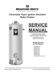
1
Atmospheric Gas Water Heaters
For Models Using White Rodgers,
Robertshaw and Honeywell Gas Control
SERVICE
MANUAL
Troubleshooting Guide
and Instructions for Service
(To be performed ONLY by
qualified service providers)
Models Covered
by This Manual:
GX225S*BN
GX155S*BN
25X78B*N
55X80B*N
M1XR65T*(BN,CX,SX)
MI75S*(BN,CX,SX)
M2XR75S*(BN,CX,SX)
MI100T*(BN,CX,SX)
65T65*(BN,CX,SX)
75T80*(BN,CX,SX)
C(S,D)W275T*(BN,CX,SX)
(*) Denotes Warranty Years
(GX155S6BN Model Shown)
Manual 238-46647-00B
Save this manual for future reference
Table of Contents
Page
3
Service
Procedure
---
Troubleshooting Chart Honeywell Gas Control
4
---
Thermocouple Testing and Replacement White Rodgers and Robertshaw Gas Control
6
AG-I
Thermopile Testing and Replacement Honeywell Gas Control
7
AG-I
Pilot Assembly Inspection Cleaning and Replacement
White Rodgers and Robertshaw Gas Control
9
AG-II
Pilot Assembly Inspection Cleaning and Replacement Honeywell Gas Control
10
AG-II
Gas Control Testing and Replacement White Rodgers and Robertshaw
12
AG-III
Gas Control Replacement Honeywell
12
AG-III
Honeywell Thermowell Testing and Replacement
16
AG-III
Honeywell Gas Control and Thermowell Replacement
18
AG-III
Burner Operation Inspection, Adjustment, Cleaning and Replacement
20
AG-IV
Dip Tube and Anode Inspection and Replacement
23
AG-V
Troubleshooting Chart White Rodgers and Robertshaw Gas Control
Page 2
2
Troubleshooting Chart
For Models Using White Rodgers or Robertshaw Thermostat
Symptom
Pilot will not light
Pilot will not
stay lit
when button is released
Pilot will light, but the
main burner will not
come on
Pilot goes out
periodically (after
heating cycles, once a
day, once a week etc.)
Not enough hot water
Probable Cause
Corrective Action
1. No incoming gas or too low gas
pressure.
2. Gas control knob set to wrong position.
3. Pilot light button not being fully
depressed when attempting to light pilot.
4. Pilot orifice or pilot tube is obstructed or
kinked.
1. Turn on gas supply and/or check line
pressure.
2. Review lighting instruction. Set
gas control to correct position.
3. Review lighting instruction. Fully depress
pilot lighting button.
4. Clean, repair or replace.
1. Poor thermocouple connection at
gas control.
2. Thermocouple not fully engaged in pilot
assembly bracket.
3. Pilot flame is not fully enveloping the
thermocouple “hot” junction.
4. Weak or defective thermocouple.
5. Open ECO on gas control.
6. Defective magnet in gas control.
1. Check connection at gas control.
Proper tightness should be finger tight plus
¼ turn.
2. Inspect thermocouple to ensure that it is
fully engaged into pilot bracket.
3. Adjust tip of thermocouple to be fully
engulfed by pilot flame.
4. Check thermocouple and replace if
necessary.
5. Check ECO continuity and replace
gas control if necessary.
6. Check magnet operation and replace
gas control if necessary.
1. Gas Control set too low for desired water
temperature.
2. Gas Control temperature is satisfied.
3. Insufficient gas supply or low gas
pressure.
4. Gas Control has wide differential or is out
of calibration.
1. Adjust temperature dial on gas control.
2. Check temperature dial setting on
gas control.
3. Check gas supply and line pressure.
4. Check gas control
for proper operation, replace if
necessary.
1. Insufficient combustion air supply.
2. Incorrect, clogged vent system/ vent
terminal or location.
3. Inconsistent gas supply or gas pressure.
1. Gas Control set too low for desired water
temperature.
2. Cold inlet water temperature is very cold.
3. High demand periods.
4. Incorrectly sized water heater for
application.
5. Gas Control is out of calibration/not
functioning.
6. Out of spec dip tube is diluting hot water
with cold water.
7. Integrated mixing device is set too low for
desired water temperature.
1. Verify adequate combustion air is available
to the unit. Check and clear Jacket slot
openings of any dirt, dust, restrictions or
other obstructions.
2. Check venting for proper sizing and proper
operation
3. Check gas supply and line pressure.
1. Check dial on gas control.
2.Extremely cold water going into the water
heater will decrease the amount of hot
water produced. It may be necessary to
temper incoming water supply.
3. Adjust high demand usage.
4. Contact Plumbing professional.
5. Check gas control
for proper operation, replace if
necessary.
6. Inspect dip tube and replace if necessary.
7. Reset device using the procedure
in the instructions included with the device.
Service
Procedure
1. See Service Procedure
AG-III, Page 12.
4. See Service Procedure
AG-II, Page 9.
4. See Service Procedure
AG-I, Page 6
5. See Service Procedure
AG-III, Page 12
6. See Service Procedure
AG-III, Page 12
2. See Installation &
operation manual.
3. See Service Procedure
AG-III, Page 12
4. See Service Procedure
AG-III, Page 12
3. See Service Procedure
AG-III, Page 12
5. See Service Procedure
AG-III, Page 12
6. See Service Procedure
AG-V, Page 23
Page 3
3
Troubleshooting Chart
For Models Using Honeywell Gas Control
Observe LED indicator on gas control. Error flash codes
are displayed with a three second pause before repeating.
Check and repair the system as noted in the troubleshooting
table below:
LED Status
Not on and/or
not flashing
Control Status
LED Indicator
Probable Cause
Pilot flame may not be present.
Pilot flame is not present.
Service
Procedure
1. Lite pilot per the instructions
located on the lighting
instructions label or the
lighting instructions located in
the installation and operation
manual.
2. See Service
Procedure AG-I,
Page 7.
Gas control is powered and waiting for the set
point knob to be turned to a water
temperature setting.
Normal operation. Adjust gas
control set point knob to
desired temperature level.
Gas control has recently been turned to the
“OFF” position. Wait until LED goes out
before attempting to relight.
Gas control was turned to the “OFF” position.
1. Wait for LED to go out.
2. Lite pilot per the instructions
located on the lighting
instructions label or the
lighting instructions located in
the installation and operation
manual.
Two flashes and a three
second pause.
Weak pilot flame detected. System will reset
when pilot flame is sufficient.
1. Thermopile failure
2. Unstable pilot.
3. Pilot tube blocked or restricted.
1. See Service
Procedure AG-I,
Page 7
2 & 3. See Service
Procedure AG-II,
Page 10.
Three flashes and a
three second pause.
Tank temperature fault.
System will reset.
Thermowell sensor out of calibration.
1. See Service
Procedure AG-III,
Page 16
Four flashes and a three
second pause.
Excessive tank temperature.
Thermowell sensor out of calibration.
1. See Service
Procedure AG-III,
Page 16
One flash and a three
second pause.
LED is on continuously
Gas control is in the “PILOT” position and
the pilot flame is detected.
Page 4
4
Troubleshooting Chart (cont.)
For Models Using Honeywell Gas Control
LED Status
Five flashes and a three
second pause.
Seven flashes and a
three second pause.
Control Status
Probable Cause
Service
Procedure
Thermowell fault
1. Damage to thermowell
wires.
2. Thermowell sensor resistance
out of range.
See Service Procedure
AG-III, Page 16
Gas control fault detected.
1. Gas control needs to be reset.
2. Gas control is wet or physically
damaged.
Lite pilot per the instructions
located on the lighting
instructions label or the
lighting instructions located in
the installation and operation
manual.
Pilot valve stuck in the open position.
Replace gas control.
See Service Procedure
AG-III, Page 18.
Eight flashes and a three Pilot flame remains on while gas control is in
the “OFF” position.
second pause.
Page 5
5
SERVICE PROCEDURE AG-I
Thermocouple Testing and Replacement
For Models Using White Rodgers or
Robertshaw Gas Control
OPEN CIRCUIT THERMOCOUPLE TESTING
Step 1.
Disconnect thermocouple from gas control.
Step 2.
Using a multimeter capable of measuring millivolts, connect
one alligator clip to the end ball or contact portion of the
thermocouple, and the other alligator clip to copper portion of
the thermocouple.
Figure 1
Step 3.
Following the lighting instruction label on the heater, proceed to light the pilot and allow to operate for
three minutes. A reading of 20 to 30 millivolts indicates good thermocouple output.
NOTE:
It will be necessary to hold the gas control
knob down in the “PILOT” position
continuously throughout this test.
THERMOCOUPLE REPLACEMENT
Step 1.
Turn off gas supply to water heater. Rotate knob of gas control to “OFF” position.
For White Rodgers gas
control, depress knob
slightly and rotate
clockwise to the “OFF”
position.
For Robertshaw gas
control, rotate knob
clockwise to the “OFF”
position.
Figure 2
Figure 3
Step 2.
Remove outer jacket door.
Step 3.
Slide open inner combustion chamber door.
Step 4.
Disconnect thermocouple from gas control. Locate other end of
thermocouple inside of combustion chamber and remove from pilot bracket. Pull firmly pulling away
from the pilot assembly.
Step 5.
Install new thermocouple into pilot bracket making certain the thermocouple is fully engaged into the pilot
bracket. Connect other end of thermocouple to gas control (finger tight + ¼ turn).
Step 6.
Route carefully through the relief opening in the combustion chamber skirt.
Step 7.
To resume operation follow the instructions located on the lighting instruction label or the lighting
instructions located in the installation and operation manual.
Step 8.
Slide inner door closed when finished.
Thermocouple position
Page 6
6
Figure 4
SERVICE PROCEDURE AG-I
Thermocouple Testing and Replacement
For Models Using Honeywell Gas Control
OPEN CIRCUIT THERMOPILE TESTING
Step 1. Disconnect red and white thermopile wires from the wire harness leading to the gas control.
Step 2. Using a multimeter capable of reading millivolts, check across thermopile leads.
Step 3. Following the instructions located on the lighting instruction label or the lighting instructions located in the
installation and operation manual, proceed to light the pilot and allow the gas control to operate for three
minutes.
NOTE:
It may be necessary to hold the gas
control knob down in the “PILOT” position
continuously throughout this test.
In an OPEN CIRCUIT test:
Any reading over 400 millivolts
indicates good thermopile output.
For readings under 400 millivolts
replacement of thermopile is
recommended.
Figure 5
CLOSED CIRCUIT THERMOPILE TESTING
Step 1. Closed circuit testing is the preferred method for testing the thermopile. Following the instructions
located on the lighting instruction label or the lighting instructions located in the installation and operation
manual, proceed to light the pilot and allow the control to operate for three minutes.
Step 2. Using a multimeter capable of measuring millivolts, measure across thermopile connections at the
gas control (see Figure 6).
In a CLOSED CIRCUIT test:
Any reading over 300 millivolts
indicates good thermopile output.
For readings under 300 millivolts
replacement of thermopile is
recommended.
NOTE:
It may be necessary to hold the gas
control knob down in the “PILOT” position
continuously throughout this test.
Thermopile
Connections at gas
control
Gas Control
Knob
Figure 6
Page 7
7
SERVICE PROCEDURE AG-I
Thermopile Testing and Replacement
For Models Using Honeywell Gas Control
THERMOPILE REPLACEMENT
Step 1. Turn off the gas supply to the water heater by rotating the gas control knob to the “OFF” position
(see Figure 7).
Step 2. Remove outer jacket door.
Step 3. Remove or slide open the inner combustion chamber door.
Step 4. Disconnect red and white thermopile wires from the wire harness leading
to the gas control.
Step 5. Disconnect the thermopile from the pilot bracket using a 7/16” open-end wrench.
Step 6. Install the new thermopile into the pilot bracket and tighten the threads using care not to damage the
thermopile lead wires. Route new wires through the appropriate opening in the combustion chamber.
Step 7. Reconnect the lead wires being careful to match the colors (red to red and white to white).
Step 8. Reinstall, or slide closed, inner combustion chamber door.
Step 9. Replace the outer door.
Step 10. To resume operation follow the instructions located on the lighting instruction label or the lighting
instructions located in the installation and operation manual.
Gas Control Knob
(Shown in OFF
position)
Figure 7
Page 8
8
SERVICE PROCEDURE AG-II
Pilot Assembly Inspection, Cleaning
and Replacement For Models Using White
Rodgers or Robertshaw Gas Control
R
For White Rodgers gas
control, depress knob
slightly and rotate
clockwise to the “OFF”
position.
PILOT ASSEMBLY INSPECTION,
CLEANING AND REPLACEMENT
Figure 8
Step 1.
Turn off gas supply to water heater. Rotate knob
of gas control to “OFF” position.
Step 2.
Remove outer jacket door.
Step 3.
Slide open inner combustion chamber door.
Step 4.
Disconnect thermocouple, pilot tube,
and feedline from gas control.
For Robertshaw gas
control, rotate knob
clockwise to the “OFF”
position.
Figure 9
NOTE: Feedline nut for natural gas control
uses right hand threads, LP control uses left hand thread.
Step 5.
Remove burner assembly from combustion chamber.
Step 6.
Remove pilot assembly from feedline.
Step 7.
Inspect pilot for the following:
Figure 10
Feedline Nut
a) Primary air openings for blockage. Must be free from any
debris (dirt, lint, etc).
b) Kinks or cracks in the pilot tube. If found,
the pilot must be replaced.
Step 8.
Inspect pilot orifice:
a) Remove ½" nut from bottom of pilot assembly.
Pilot Orifice
Figure 11
Primary Air
Opening
b) Remove pilot tube and pilot orifice.
c) inspect pilot orifice for blockage, must be cleaned or replaced.
Step 9.
Install pilot assembly to feedline, secure with screw from step 6.
Step 10.
Re-Install burner assembly into combustion chamber, connect feedline, pilot tube and thermocouple
to gas control.
Step 11.
Slide inner combustion chamber door closed and re-attach outer jacket door.
Step 12.
To resume operation follow the instructions located on the lighting instruction label or the lighting
instructions located in the installation and operation manual.
Page 9
9
SERVICE PROCEDURE AG-II
Pilot Assembly Inspection, Cleaning
and Replacement For Models Using
Honeywell Gas Control
R
PILOT ASSEMBLY INSPECTION,
CLEANING AND REPLACEMENT
Step 1. Turn off the gas supply to the water
Heater. Rotate gas control knob to the
“OFF” position.
Primary Air
Opening
Step 2. Remove outer jacket door.
Step 3. Remove burner assembly per
Service Procedure AG-IV page 20.
Figure 12
Step 4. Remove the pilot assembly from the burner assembly.
Step 5. Inspect the pilot assembly for the following:
Pilot Orifice
a)Primary air opening for any blockage .
Must be free from any debris (dirt, lint, dust, etc.).
b) Kinks or cracks in the pilot tube. If found, the pilot
must be replaced.
Step 6. Inspect pilot orifice:
Figure 13
a) Remove 7/16” nut from the bottom of the pilot assembly.
b) Remove pilot tube and pilot orifice.
c) Inspect pilot orifice for blockage, must be free from any debris (dirt, lint, dust, etc.).
d) Reassemble pilot orifice and pilot tube to pilot assembly.
Step 7. Install pilot assembly to burner assembly using the screw from Step 4.
Step 8. Reinstall burner assembly per Service Procedure AG-IV page 22: Steps 10 through 12.
Step 9. To resume operation follow the instructions located on the lighting instruction label or the lighting
instructions located in the installation and operation manual.
Step 10. Check all gas connections for gas leaks using a soapy water solution.
Page 10
10
SERVICE PROCEDURE AG-II
Pilot Assembly Inspection, Cleaning
and Replacement For Models Using
Honeywell Gas Control
R
IGNITER/ELECTRODE TESTING AND
REPLACEMENT
With the pilot not in operation (no pilot flame) the igniter and electrode circuit function can be observed by
opening the combustion chamber door and viewing whether there is a sparking action.
Step 1. Make sure the gas control is in the “OFF” position.
Step 2. Remove outer jacket door.
Repeatedly Depress
Igniter
Step 3. Slide open or remove the inner
combustion chamber door.
Step 4. Depress the igniter button repeatedly while viewing
the spark through the open door of the combustion
chamber. If there is no spark proceed to Step 5.
If there is a spark, the igniter is OK.
Figure 14
Step 5. Remove the lead wire from the igniter at the connector
provided for this. Hold the igniter lead from the gas valve
close to an unpainted metal surface (such as the burner feedline)
and depress the igniter button (see Figure 15). If there is a spark the igniter is OK.
If no spark is present the igniter is not functioning and the gas control
must be replaced per Service Procedure AG-III page 18.
Look for spark in
the gap
Figure 15
Page 11
11
SERVICE PROCEDURE AG-III
Gas Control Testing and Replacement
For Models using White Rodgers or
Robertshaw Gas Control
Gas Control Testing and Replacement
The gas control is a non repairable device. If trouble shooting has determined a problem with the gas control, it must be
replaced.
If the burner and/or pilot do not function, service checks for gas pressure, thermocouple output, magnet assembly and
ECO are to be performed. If these check OK, the gas control may be faulty.
LINE PRESSURE
The gas control is designed for a maximum line pressure of 14.0" w.c. and a minimum line pressure of 1.0"w.c. over the
water heater rated manifold pressure. Line pressure must be checked with burner on and burner off to assure proper
readings.
MANIFOLD PRESSURE TESTING (this procedure assumes a maximum line pressure of 14.0" w.c.)
Step 1.
Set gas control to “OFF” position.
Step 2.
Remove pressure tap plug and install
pressure tap.
Step 3.
Connect manometer to pressure tap.
Figure 16
Step 4.
Follow lighting instructions and proceed to light
main burner and observe manometer reading.
Step 5.
Proper operating range for natural gas is 4.0 ±0.3" W.C.
Proper operating range for L.P. gas is 10.0 ±0.5" W.C.
Step 6.
Figure 17
If pressure is OK, set gas control to “OFF”
remove manometer and pressure tap and replace pressure tap plug. Check for gas leaks before placing water
heater back in operation. If pressure is out of the specification noted in step 5, proceed to step 7 or 8 for proper
service procedure.
Step 7.
For White Rodgers control, the manifold pressure is not adjustable. If manifold pressure is outside the range
in step 5, the control must be replaced.
Step 8.
For Robertshaw control, the manifold pressure is adjustable, proceed to step 9 for adjustment procedure
Step 9.
While burner is in operation, remove regulator access cap to expose the regulator adjusting screw. With small
screw driver, rotate adjusting screw clockwise to increase pressure and counter clockwise to decrease pressure.
Step 10.
Figure 18
Figure 19
Replace regulator access cap, set gas control to “OFF”. Remove manometer and
pressure tap and replace pressure tap plug. Check for gas leaks before placing water heater back in operation.
Page 12
12
Pressure Tap
Shown
Installed
SERVICE PROCEDURE AG-III
Gas Control Testing and Replacement
For Models using White Rodgers or
Robertshaw Gas Control
THERMOCOUPLE TESTING
See SERVICE PROCEDURE AG-II
MAGNET ASSEMBLY TESTING (White Rodgers Control)
Step 1.
Following the lighting instruction label on the heater, proceed to light the pilot and allow to operate for
three minutes. If the pilot will not stay lit, hold the pilot button (located on the combination
thermostat/gas valve) down during this test
Step 2.
Using a multimeter capable of measuring millivolts, connect one lead
using an alligator clip to the copper sheath of the thermocouple, use the second lead of the multi meter to
probe the top terminal located at the back of the gas control.
Alligator clip to copper sheath
of thermocouple
Probe top terminal on back of
gas control
Step 6.
Step 7.
Figure 20
With a meter reading of 13 millivolts or greater, rotate knob of gas control to the
“OFF” position.
The magnet should remain closed for a drop of at least 6 millivolts. You will here a “snap” or “click” sound
when the magnet opens, if you hear this sound prior to a drop of 6 millivolts, the magnet is out of
specification and the gas control should be replaced.
MAGNET ASSEMBLY TESTING (Robertshaw Control)
Step 1.
Disconnect thermocouple from gas control.
Step 2.
Connect a thermocouple adaptor
(BWC P/N 239-44642-00, Robertshaw P/N 75036) at the
thermocouple location in the gas control.
Step 3.
Reconnect thermocouple to adaptor. Make certain all connections
are tight (finger tight plus ¼” turn).
Step 4.
Using a multimeter capable of measuring millivolts, connect one
alligator clip to the set screw of the adaptor and the other alligator
clip to copper portion of the thermocouple.
Figure 21
Figure 22
Step 5.
Following the lighting instruction label on the heater, proceed to light the pilot and allow to operate for
three minuets.
Step 6.
With a meter reading of 13 millivolts or greater, rotate knob of gas control to the
“OFF” position.
Step 7.
The magnet should remain closed for a drop of at least 6 millivolts. You will here a “snap” or “click” sound
when the magnet opens, if you hear this sound prior to a drop of 6 millivolts, the magnet is out of
specification and the gas control should be replaced.
Page 13
13
SERVICE PROCEDURE AG-III
Gas Control Testing and Replacement
For Models using White Rodgers or
Robertshaw Gas Control
ECO (Energy Cut Off) TESTING
Step 1.
Disconnect thermocouple from gas control.
Step 2.
Using a multimeter capable of measuring Ohms (or continuity),
attach one lead (alligator clip) to the pilot tube. Insert the other lead
(probe) fully into the magnet opening, Be sure the probe makes
contact only at the top center of the magnet opening. Do not allow
the probe to make contact with the threaded sides of the opening.
Step 3.
Figure 23
If continuity is indicated, the ECO is OK. If continuity is not indicated, the ECO has opened and the
gas control must be replaced.
GAS CONTROL REPLACEMENT
For White Rodgers gas
control, depress knob
slightly and rotate
clockwise to the “OFF”
position.
Step 1. Rotate knob of the gas control
to the “OFF” position.
Step 2. Turn off gas supply to water heater.
Step 3. Disconnect gas supply line from
gas control.
Figure 24
Step 4. Turn off water supply and drain water heater completely.
For Robertshaw gas
control, rotate knob
clockwise to the “OFF”
position.
Step 5. Remove outer jacket burner access door.
Step 6. Slide open inner combustion chamber door.
Figure 25
Figure 26
Page 14
14
SERVICE PROCEDURE AG-III
Gas Control Testing and Replacement
For Models using White Rodgers or
Robertshaw Gas Control
Step 7. Removal of gas control.
a) Disconnect main burner feedline, pilot tube and thermocouple
from gas control & remove burner from combustion chamber.
NOTE: Feed line nut for natural gas control uses right hand threads,
LP control uses left hand thread.
b) Remove gas control from heater,
rotating counter clockwise using a control body wrench or a
length of ½" NPT pipe threaded into inlet of control.
Wrench Boss
To remove or install control, insert only
½" NPT threaded pipe into inlet and
use to loosen or tighten control.
Step 8. Installation of gas control.
Figure 27
a) Install new gas control using a control body wrench or a length of ½" NPT
pipe threaded into inlet of control. DO NOT OVER TIGHTEN. Use caution not to damage cast
aluminum body of gas control. Be certain not to damage the bundled wire
leads.
NOTE: gas control must be installed in proper upright position to
assure the feedline will align properly at the inner door flange.
DO NOT OVER TIGHTEN. If control is turned past proper alignment, do not
reverse direction to align.
b) Reattach main burner feedline, pilot tube and thermocouple to gas control.
NOTE: Feedline nut for natural gas control uses right hand threads,
LP control uses left hand thread.
c) Connect gas supply piping to inlet of control. Use back up wrench on wrench boss of control, never
use back up wrench on body of control.
Step 9.
Reconnect gas supply to gas control.
Step 10.
Resume water supply to water heater. Be sure tank is full of water.
Step 11.
Slide inner combustion chamber door closed
Step 12.
Re-attach outer jacket door.
Step 13.
To resume operation follow the instructions located on the lighting instruction label or the lighting instructions
located in the installation and operation manual.
Page 15
15
SERVICE PROCEDURE AG-III
Honeywell Thermowell Testing and
Replacemet
HONEYWELL THERMOWELL TESTING
Step 1. If gas control has gone into lockout due to excessive tank temperature (four flashes and a three second
pause) reset the gas control to the “OFF” position. Then follow the instructions located on the lighting
instruction label or the lighting instructions located in the installation and operation manual.
Step 2. Observe the water heater operation. If the gas control continues to lockout due to excessive tank
temperature proceed to Step 3, thermowell testing, to determine the cause.
Step 3. To perform thermowell testing turn the gas control to the “OFF” position and disconnect the
thermowell harness from the gas control.
Disconnect
thermowell wire
harness
Figure 28
Figure 29
CAUTION
DO NOT Use standard multimeter probes to
test. Doing so will damage connector. Use
special pin type electronic probes or small
diameter wire pins inserted into connector
Figure 30
Step 4. Using a multimeter set to measure Ohms determine the resistance of the thermowell sensor (See
caution on this page).
Step 5. Hold one probe in the center pin and measure the outside positions pins (see figure 29 & 30).
Step 6. Refer to Table 1 on page 17 to determine the correct resistance value for the water heater tank
temperature.
Step 7. If the resistance values are correct the gas control needs to be replaced. If they are incorrect the
thermowell needs to be replaced.
Page 16
16
SERVICE PROCEDURE AG-III
Honeywell Thermowell Testing and
Replacement
DETERMINE WATER HEATER TANK TEMPERATURE
NOTE:
It is important to understand once the resistance
for the thermowell is determined, water flow
through the water heater should not occur. Prior
to performing the steps below turn off cold water
supply to the water heater. This will prevent cold
water flow into the tank affecting the resistance
value of the thermowell.
WARNING
Stored water may be HOT when
performing the following steps in this
procedure. Take necessary precaution to
prevent personal injury
CAUTION
Step 1. Turn the gas control to the “OFF” position and
disconnect the thermowell harness from the gas control.
DO NOT use standard multimeter
probes to test. Doing so will damage
connector. Use special pin type
electronic probes or small diameter
wire pins inserted into connector
Step 2. Using a multimeter set to measure Ohms determine the resistance of the thermowell sensor (See
caution on this page).
Step 3. Hold one probe in the center pin and measure the outside positions pins (see figure 29 & 30, page 16).
Step 4. Draw approximately 1 quart of water from the drain valve and immediately measure the water
temperature using an accurate thermometer. It may be necessary to open a hot water faucet to allow
the heater to drain.
Step 5. Refer to Table 1 below to determine the correct resistance value for the water heater tank temperature.
Example: If the temperature of the water is 84°F, then the resistance through the sensor would be 8449 (see
shaded area). NOTE: Sensor resistance increases as the temperature falls.
Sensor Resistance at Various Temperatures
(Table 1)
°F
40
50
60
70
80
90
100
110
120
130
140
150
160
170
180
190
200
0
26109
19906
15314
11884
9299
7333
5827
4663
3758
3048
2488
2043
1688
1402
1170
982
828
1
25400
19383
14925
11592
9078
7165
5697
4562
3679
2986
2439
2004
1656
1376
1150
965
814
2
24712
18876
14548
11308
8862
7000
5570
4464
3602
2925
2391
1966
1625
1351
1129
949
801
3
24045
18383
14180
11032
8653
6839
5446
4368
3527
2866
2344
1928
1595
1327
1110
933
788
In Degrees
4
23399
17905
13823
10763
8449
6683
5326
4274
3453
2808
2298
1891
1566
1303
1090
917
775
F
5
22771
17440
13477
10502
8250
6531
5208
4183
3382
2752
2253
1856
1537
1280
1071
901
762
6
22163
16990
13140
10248
8057
6383
5094
4094
3312
2697
2209
1820
1509
1257
1953
886
749
7
21573
16553
12812
1000
7869
6238
4982
4006
3244
2643
2166
1786
1481
1235
1035
871
737
8
21000
16128
12494
9760
7685
6098
4873
3922
3177
2590
2124
1753
1454
1213
1017
857
725
9
20445
15715
12185
9526
7507
5961
4767
3839
3112
2538
2083
1720
1427
1191
999
842
713
Page 17
17
SERVICE PROCEDURE AG-III
Honeywell Gas Control and Thermowell
Replacement
HONEYWELL GAS CONTROL & THERMOWELL REMOVAL
Gas Control
Thermowell
Step 1. Turn the gas control knob to the “OFF” position.
Step 2. Turn off water supply and drain water heater completely.
Step 3. Turn off and disconnect gas supply to control
Step 4. Disconnect wire harness and burner
assembly from the gas control.
Figure 31
Step 5. Remove gas control and thermowell by rotating flats of the thermowell counter clockwise.
HONEYWELL GAS CONTROL REMOVAL FROM THERMOWELL
NOTE; Following the instructions below allows the removal of the gas control from the thermowell without
removing the thermowell from the tank.
Step 1. Turn the gas control knob to the “OFF” position.
Step 2. Turn off and disconnect gas supply piping to the gas control.
Step 3. Disconnect wire harnesses and burner assembly from the gas control.
Step 4. Using the gas control service tool (part number 239-45991-00) available from your Bradford White
parts supplier, insert tool into the back of the gas control (see Figure 32 & 33).
View from back of
gas control for clarity
Insert tool into
back of gas
control
Figure 32
Figure 33
Step 5. Pivot service tool towards water heater as far as possible (see Figure 34). Lift up straight on gas
control. The gas control should move about 1/8”. Hold gas control in position and remove tool.
Lift straight up on the gas control to remove completely from the thermowell.
Figure 34
18
Page 18
SERVICE PROCEDURE AG-III
Honeywell Gas Control and Thermowell
Replacement
HONEYWELL GAS CONTROL ASSEMBLY TO THERMALWELL
Step 1. Install threaded end of thermowell into water heater. When tight, be sure thermowell flange is
positioned so that thermowell relief opening is in the 6 o’clock position for proper control alignment
(see Figure 35).
Thermowell
flange slots
Route wire through
relief opening
6 o’clock position
Figure 35
Step 2. Route lead wires through the relief opening (see Figure 35).
Step 3. Align slots located on the thermowell flange with tabs located on the back of the gas control
(see Figure 36).
Gas control tabs
Figure 36
Step 4. Carefully push the gas control back onto the thermowell flange.
Step 5. Install burner assembly and reconnect pilot tubing and main burner feed line to gas control.
Step 6. Reconnect wire harness and igniter wire to the gas control.
Step 7. Resume water supply to water heater and check for leaks. Be sure tank is full of water.
Step 8. Reconnect the gas supply to gas control. Check for gas leaks using a soapy water solution.
Step 9. To resume operation follow the instructions located on the lighting instruction label or the lighting
instructions located in the installation and operation manual.
Page 19
19
SERVICE PROCEDURE AG-IV
Burner Operation Inspection, Adjustment
Cleaning and Replacement
R
MAIN BURNER: Inspection, Adjustment, Cleaning and Replacement
At periodic intervals (not more then 6 months) a visual inspection should be made of the main burner for proper operation
and to insure no debris accumulating.
Main burner should light smoothly from pilot and burn with a blue flame with a minimum of yellow tips.
Steel burner models have a self adjusting air mixture and do not have an adjustable air shutter. Cast iron burner can have
the gas and air mixture properly proportioned by adjusting the air shutter on the mixer face of the main burner (see step 2
below).
Main burner must be free from any debris accumulation that may effect burner operation (see burner cleaning procedure
on page 21).
CAST IRON BURNER ADJUSTMENT
WARNING
Inner door and burner components may be HOT when performing this operation. Take
necessary precaution to prevent personal injury.
Step 1.
With main burner in operation slide the inner combustion chamber door open.
Step 2.
To adjust for proper burning, loosen the air shutter nut, rotate the shutter to close the opening in the burner,
then slowly rotate the shutter until the yellow tips are minimized and the flame becomes blue. Tighten the air
shutter nut. Too much air will cause the flame to lift off the burner ports and create noisy burner operation.
Too little air (yellow tips) will result in soot formation.
Air Shutter
Nut
Figure 37
Page 20
20
SERVICE PROCEDURE AG-IV
Burner Operation Inspection, Adjustment
Cleaning and Replacement
MAIN BURNER: Inspection, Adjustment, Cleaning and Replacement (cont.)
Step 3.
Fully inspect combustion chamber for debris or carbon build up.
Step 4.
Be certain that thermocouple or thermopile, and pilot tube are routed correctly through the relief opening in
the combustion chamber.
Position thermocouple or
thermopile, and pilot tube.
Step 5.
Burner should operate as adjusted in step 2 on page 20, if not, repeat procedure
compensating air shutter position for proper burner operation with inner door closed.
Step 6.
It may be necessary to clean main burner or main burner orifice to achieve proper burner operation. If
cleaning is required proceed to burner cleaning procedure below.
Figure 38
BURNER CLEANING (Steel & Cast Iron)
Step 1.
Slide open or remove inner combustion chamber door.
Step 2.
Disconnect main burner feed line, pilot tube, and thermocouple or thermopile from gas control
and remove burner assembly from combustion chamber.
NOTE: Feedline nut for natural gas control uses right hand threads,
LP control uses left hand threads.
Step 3.
Thoroughly inspect burner surface area and burner ports and remove any debris build up.
Burner Surface Area
Figure 39
Figure 40
Burner Port Area
Step 4.
Figure 41
On cast iron burners, inspect
for any debris build up inside
burner venturi. If found,
disconnect main burner feedline
from burner and remove debris
build up.
Figure 42
Burner Venturi
Opening
Figure 43
Feedline
Page 21
21
SERVICE PROCEDURE AG-IV
Burner Operation Inspection, Adjustment
Cleaning and Replacement
BURNER CLEANING (Cont.)
Step 5.
Steel Burner:
Disconnect (unscrew) burner from main burner orifice.
Cast Iron Burner:
Disconnect (unscrew) main burner feedline from burner.
Figure 44
Step 6.
Remove main burner orifice from feedline.
Inspect and clean if necessary.
Step 7.
Inspect pilot assembly per service procedure AG-II.
Step 8.
Reassemble burner assembly.
Step 9.
Inspect combustion chamber area of water heater and clean if needed prior to reinstallation of burner
assembly.
Step 10.
Reinstall burner assembly into combustion chamber, reconnect feedline, thermocouple or thermopile, pilot
tube and igniter wire (for applicable models) to the gas control.
Step 11.
Slide close or attach inner combustion chamber door and reattach outer jacket door.
Step 12.
To resume operation, follow the instructions located on the lighting instruction label or the lighting
instructions located in the installation and operation manual.
Page 22
22
Figure 45
SERVICE PROCEDURE AG-V
Diptube and Anode
Inspection and Replacement
R
DIPTUBE INSPECTION AND REPLACEMENT
WARNING
Water heater components and stored water may be HOT when performing the following
steps in this procedure. Take necessary precaution to prevent personal injury.
Step 1.
Turn the gas control knob to the “OFF” position.
For White Rodgers Control,
depress knob slightly and
rotate clockwise to the “OFF”
position.
Figure 46
For Honeywell gas
control, rotate knob
counter clockwise to the
“OFF” position.
For Robertshaw Control,
rotate knob clockwise to the
“OFF” position.
Figure 47
Figure 48
Step 2.
Turn off cold water supply to water heater. Connect hose to drain spigot of water heater and route to a
suitable drain. Open a nearby hot water faucet to vent water heater for draining. Open drain spigot of
water heater and allow to drain.
Step 3.
Disconnect plumbing system from inlet nipple/diptube.
Step 4.
With an appropriate wrench, remove inlet nipple/diptube from the water heater. Use caution not to damage
the nipple threads.
Step 5.
Visually inspect inlet nipple/diptube. Inlet nipple/diptube should be free of cracks and any blockage.
The small curved openings should be open and free of any blockage.
Anti-siphon hole located approximately 6" from the bottom of nipple, should be free of any blockage.
Any damage such as cracks, restriction due to deformation or unintentional holes are not field repairable
and the inlet nipple/dip tube must be replaced.
Step 6.
Upon completion of inspection or subsequent replacement, reinstall inlet nipple/diptube into water heater.
Reconnect plumbing system to inlet nipple/diptube, resume cold water supply and check for leaks.
Step 7.
To resume operation follow the instructions located on the lighting instruction label or the lighting instructions
located in the installation and operation manual.
Page 23
23
SERVICE PROCEDURE AG-V
Diptube and Anode
Inspection and Replacement
ANODE INSPECTION AND REPLACEMENT
WARNING
Water heater components and stored water may be HOT when performing the following
steps in this procedure. Take necessary precaution to prevent personal injury.
Step 1.
Turn gas control knob to “OFF” position.
For White Rodgers Control,
depress knob slightly and
rotate clockwise to the “OFF”
position.
For Honeywell gas
control, rotate knob
counter clockwise to the
“OFF” position.
Figure 49
For Robertshaw Control,
rotate knob clockwise to the
“OFF” position.
Figure 50
Figure 51
Step 2.
Turn off cold water supply to water heater. Connect hose to drain spigot of water heater and route to a
suitable drain. Open a nearby hot water faucet to vent heater for draining. Open drain spigot of water
heater and allow to drain.
Step 3.
Disconnect plumbing system from outlet nipple/anode.
Step 4.
With an appropriate wrench, remove outlet nipple/anode from the water heater. Use caution not to damage
the nipple threads.
Step 5.
Visually Inspect outlet nipple/anode. Outlet nipple/anode may show signs of depletion, this is normal.
If depletion is ½ of the original anode diameter (approximately ¾” diameter), replacement is recommended.
If any of the steel core of the anode is exposed, replacement is recommended.
Step 6.
Upon completion of inspection or subsequent replacement, reinstall outlet nipple/anode into water heater.
Reconnect plumbing system to outlet nipple/anode, resume water supply and check for leaks.
Step 7.
To resume operation, follow the instructions located on the lighting instruction label or the lighting
instructions located in the installation and operation manual.
Page 24
24