1
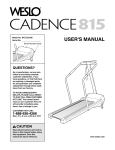
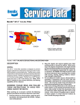
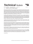
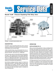
SD-08-2402
Bendix® Cyclone DuraDrain™ Trailer Water Separator
DELIVERY PORT
“OUT”
DELIVERY PORT
“OUT”
.28 DIA.
MOUNTING
HOLES
SUPPLY PORT
“IN”
SCREENS
SUPPLY PORT
“IN”
O-RING
PURGE NUT WITH
DRAIN
PURGE NUT WITH
CHECK VALVE
DRAIN
FIGURE 1 - CYCLONE DURADRAIN™ TRAILER WATER SEPARATOR
DESCRIPTION
The Cyclone DuraDrain™ trailer water separator can be
installed in the trailer control or in the supply line near the
gladhand. It removes water and contaminants that can
cause brakes to drag and improves the life of the trailer
system components.
OPERATION (See Figure 1)
Compressed air enters the supply port of the Cyclone
DuraDrain™ trailer water separator. The air pressure pushes
down on the check valve contained in the purge nut and
closes the purge nut drain port. When air enters the supply
port of the Cyclone DuraDrain™ trailer water separator a
cyclonic action is created.
The cyclonic motion separates the oil, water and particulates.
The oil, water and particulates gravitate to the bottom of the
Cyclone DuraDrain™ trailer water separator where they
collect. When the air pressure above the purge nut check
valve returns to atmospheric pressure, the check valve moves
up and off its seat. The contaminants then drain through
the purge nut drain port.
If water from a gladhand enters the supply port and no air
pressure is applied, gravity will allow the water and
contaminants to drain through the purge nut drain port.
GENERAL SAFETY GUIDELINES
WARNING! PLEASE READ AND FOLLOW
THESE
INSTRUCTIONS
TO AVOID
PERSONAL INJURY OR DEATH:
When working on or around a vehicle, the following
general precautions should be observed at all times.
1. Park the vehicle on a level surface, apply the
parking brakes, and always block the wheels.
Always wear safety glasses.
2. Stop the engine and remove ignition key when
working under or around the vehicle. When
working in the engine compartment, the engine
should be shut off and the ignition key should be
removed. Where circumstances require that the
engine be in operation, EXTREME CAUTION should
be used to prevent personal injury resulting from
contact with moving, rotating, leaking, heated or
electrically charged components.
1
3. Do not attempt to install, remove, disassemble or
assemble a component until you have read and
thoroughly understand the recommended
procedures. Use only the proper tools and observe
all precautions pertaining to use of those tools.
4. If the work is being performed on the vehicle’s air
brake system, or any auxiliary pressurized air
systems, make certain to drain the air pressure
from all reservoirs before beginning ANY work on
the vehicle. If the vehicle is equipped with an
AD-IS ® air dryer system or a dryer reservoir
module, be sure to drain the purge reservoir.
5. Following
the
vehicle
manufacturer’s
recommended procedures, deactivate the
electrical system in a manner that safely removes
all electrical power from the vehicle.
6. Never exceed manufacturer’s recommended
pressures.
7. Never connect or disconnect a hose or line
containing pressure; it may whip. Never remove a
component or plug unless you are certain all
system pressure has been depleted.
8. Use only genuine Bendix ® replacement parts,
components and kits. Replacement hardware,
tubing, hose, fittings, etc. must be of equivalent
size, type and strength as original equipment and
be designed specifically for such applications and
systems.
9. Components with stripped threads or damaged
parts should be replaced rather than repaired. Do
not attempt repairs requiring machining or welding
unless specifically stated and approved by the
vehicle and component manufacturer.
10. Prior to returning the vehicle to service, make
certain all components and systems are restored
to their proper operating condition.
11. For vehicles with Antilock Traction Control (ATC),
the ATC function must be disabled (ATC indicator
lamp should be ON) prior to performing any vehicle
maintenance where one or more wheels on a
drive axle are lifted off the ground and moving.
NUT
WASHER
MOUNTING SPACER
(KIT 5014792)
CYCLONE DURADRAIN™
TRAILER WATER
SEPARATOR
MOUNTING BOLTS
FIGURE 2 - INSTALLATION
REMOVING
Disconnect both upstream gladhands from the trailer or dolly
before beginning work on the Cyclone DuraDrain™ trailer water
separator.
1. Disconnect the supply and delivery line fittings.
2. Remove the mounting hardware, and spacer if applicable,
that secures the Cyclone DuraDrain™ trailer water
separator to the trailer frame rail.
INSTALLATION
A Cyclone DuraDrain™ trailer water separator can be installed
in the control and/or the supply line of the trailer between
the gladhand and the first valve in the trailer system. See
Figure 3 Trailer Schematic.
1. Identify the control and/or the supply line that the Cyclone
DuraDrain™ trailer water separator is to be installed in.
The trailer water separator should be installed at the
lowest point on the air line, but should not be too low
causing a dip in the air line. The Cyclone DuraDrain™
trailer water separator must be installed vertically with
the purge nut pointing down to the ground to allow for
adequate draining.
2. Locate a mounting position on the trailer frame rail or
crossmember. Using the Cyclone DuraDrain™ trailer
water separator as a template, mark the location of the
mounting holes. Drill two mounting holes. Consult with
the trailer manufacturer prior to drilling any holes in the
frame rail or crossmember. If a mounting spacer is used,
install as shown in Figure 2. Secure using grade 2 or 5
mounting hardware.
3. Cut the air line and install a 3/8" NPT male fitting at
each end. Connect the air lines to the supply and delivery
ports of the Cyclone DuraDrain™ trailer water separator.
2
SPRING BRAKE
CYCLONE DURADRAIN™
TRAILER WATER
SEPARATOR
CONTROL
ABS UNIT OR
RELAY VALVE
SUPPLY
PLACEMENT OF OPTIONAL
SUPPLY LINE CYCLONE
DURADRAIN™ TRAILER WATER
SEPARATOR
SR-5™ SPRING
BRAKE VALVE
FIGURE 3 - TRAILER SCHEMATIC
SERVICE INTERVALS
Service intervals are dependent on specific environmental
and operational factors that control the amount of
contamination removed by the Cyclone DuraDrain™ unit.
Experience should be used to determine how frequently
the unit must be serviced. As a recommended minimum,
every 12 months, 100,000 miles or 3,600 operating hours,
perform the Operational and Leakage Tests. Inspect the
Cyclone DuraDrain™ unit for unrestricted airflow and
blockage from debris collection. Remove the purge nut
and service according to the “Disassembly and Cleaning”
instructions. If the purge nut is damaged or improperly
functioning, replace with the purge nut service kit.
OPERATIONAL AND LEAKAGE TESTS
2. When full system pressure is reached, and the spring
brakes are fully released, apply a soap solution to the
supply and delivery ports of the Cyclone DuraDrain™
trailer water separator. Apply the brakes and check for
leaks. A 1" bubble in 5 seconds is permissible.
DISASSEMBLY AND CLEANING
Periodically inspect and clean the Cyclone DuraDrain™
trailer water separator. Do not disconnect or remove the
Cyclone DuraDrain™ body.
1. Disconnect both upstream gladhands from the trailer or
dolly before beginning work on the Cyclone DuraDrain™
trailer water separator. All servicing can be done without
disconnecting the air lines from the body.
Connect the tractor air lines to the trailer being tested. Block
all wheels or hold the vehicle by means other than air brakes.
2. Remove the 1-3/8" hex purge nut assembly with o-ring
from the bottom of the leaking Cyclone DuraDrain™ trailer
water separator. Remove the o-ring from the purge nut.
Supply Line (Emergency)
AIR CLEANING
1. Build tractor and trailer to full system pressure by placing
the park control valve and the trailer air supply valve in
the charge position.
A rubber pressure-activated valve is located under the screen
in the purge nut. The screen is permanently installed and
cannot be removed. Attempts to remove the screen and
access the pressure-activated valve will damage the purge
nut necessitating its replacement.
2. When full system pressure is reached, and the spring
brakes are fully released, apply a soap solution to the
supply and delivery ports of the Cyclone DuraDrain™
trailer water separator. A 1" bubble in 5 seconds is
permissible.
Control Line (Service)
1. Build tractor and trailer to full system pressure by placing
the park control valve and the trailer air supply valve in
the charge position.
WARNING NOTE: an air gun blowing backward through the
drain hole in the bottom of the nut can dislodge the pressureactivated valve necessitating replacement of the purge nut.
The most common cause of air leakage is sandy debris on
the valve seat inside the purge nut. Dislodging and ejecting
the debris can restore leak-free operation.
3
3. Gently tap the purge nut upside down and sideways to
dislodge possible debris taking care not to damage the
screen.
Maintenance Kits .......Piece No.
Purge Nut Service Kit ............. 5013824
Mounting Spacer Kit ............... 5014792
4. Blow air in the normal downward direction through the
screen to remove debris out the drain hole. Review the
warning note.
5. Inspect the o-ring for damage and replace if necessary.
Apply a small amount of barium grease to o-ring and
place it into the o-ring groove of the purge nut assembly.
Reinstall the purge nut into the Cyclone DuraDrain™ body
using hand tools with low to moderate torque (150 inlbs).
6. Reapply air pressure and determine if the leak has been
eliminated.
.
SOLVENT CLEANING
If air leakage was not eliminated by air cleaning, the purge
nut may be cleaned in a mineral spirits parts washer. Repeat
the removal procedure steps 1 and 2 before proceeding.
7. Wash the hex purge nut in mineral spirits parts washer.
Flow solvent downward through the screen and out the
drain hole.
8. For stubborn debris, the purge nut may be soaked in
the parts washer overnight to dissolve persistent
deposits.
9. Apply a small amount of barium grease to o-ring and
place it into the o-ring groove of the purge nut assembly.
Reinstall the purge nut into the Cyclone DuraDrain™ body
using hand tools with low to moderate torque (150 inlbs).
10. Reapply air pressure and determine if the leak has been
eliminated.
11. If the air leak persists, replace the entire purge nut with
Bendix service kit piece number 5013824.
4
BW2440 © 2006 Bendix Commercial Vehicle Systems LLC. All rights reserved. 7/2006
Printed in U.S.A.