1
VALVE ADJUSTMENT
™
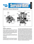
If the RV-1 valve does not deliver as described, and leakage
is minimal, the valve can be readjusted as follows.
1. Remove lockwire (if used).
2. Loosen the cap lock nut while holding the adjusting cap
stationary.
3. Turn the adjusting cap clockwise to increase pressure,
counter clockwise to reduce pressure.
4. The lock nut should be tightened after readjustment, while
holding the adjustment cap stationary.
5. Recheck the delivery pressure as described.
6. Reattach the lockwire and replace the seal if used.
If the RV-1™ valve does not function as described or if
excessive leakage occurs, it is recommended that it be
repaired/replaced with genuine Bendix parts.
PREVENTIVE MAINTENANCE
Important: Review the Bendix Warranty Policy before
performing any intrusive maintenance procedures. A warranty
may be voided if intrusive maintenance is performed during
the warranty period.
No two vehicles operate under identical conditions, as a
result, maintenance intervals may vary. Experience is a
valuable guide in determining the best maintenance interval
for air brake system components. At a minimum, the RV-1™
valve should be inspected every 6 months or 1500 operating
hours, whichever comes first, for proper operation. Should
the RV-1™ valve not meet the elements of the operational
tests noted in this document, further investigation and service
of the valve may be required.
WARNING! PLEASE READ AND FOLLOW
THESE
INSTRUCTIONS
TO AVOID
PERSONAL INJURY OR DEATH:
When working on or around a vehicle, the following
general precautions should be observed at all times.
1. Park the vehicle on a level surface, apply the
parking brakes, and always block the wheels.
Always wear safety glasses.
2. Stop the engine and remove ignition key when
working under or around the vehicle. When
working in the engine compartment, the engine
should be shut off and the ignition key should be
removed. Where circumstances require that the
engine be in operation, EXTREME CAUTION should
be used to prevent personal injury resulting from
contact with moving, rotating, leaking, heated or
electrically charged components.
2
3. Do not attempt to install, remove, disassemble or
assemble a component until you have read and
thoroughly understand the recommended
procedures. Use only the proper tools and observe
all precautions pertaining to use of those tools.
4. If the work is being performed on the vehicle’s air
brake system, or any auxiliary pressurized air
systems, make certain to drain the air pressure from
all reservoirs before beginning ANY work on the
vehicle. If the vehicle is equipped with an AD-IS®
air dryer system or a dryer reservoir module, be
sure to drain the purge reservoir.
5. Following
the
vehicle
manufacturer’s
recommended procedures, deactivate the electrical
system in a manner that safely removes all
electrical power from the vehicle.
6. Never exceed manufacturer’s recommended
pressures.
7. Never connect or disconnect a hose or line
containing pressure; it may whip. Never remove a
component or plug unless you are certain all
system pressure has been depleted.
8. Use only genuine Bendix ® replacement parts,
components and kits. Replacement hardware,
tubing, hose, fittings, etc. must be of equivalent
size, type and strength as original equipment and
be designed specifically for such applications and
systems.
9. Components with stripped threads or damaged
parts should be replaced rather than repaired. Do
not attempt repairs requiring machining or welding
unless specifically stated and approved by the
vehicle and component manufacturer.
10. Prior to returning the vehicle to service, make
certain all components and systems are restored
to their proper operating condition.
REMOVAL AND INSTALLATION
REMOVAL
1. Block and hold the vehicle by means other than air brakes.
2. Drain the service and isolated reservoirs.
3. Disconnect the air lines from the pressure reducing valve.
4. Loosen the valve mounting bolts and remove the valve.
INSTALLATION
1. Check and clean air lines to valve.
2. Mount the valve securely with bolts and lockwashers.
3. Reconnect the lines to the valve.