1
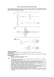
VALVE DISASSEMBLY
ASSEMBLY
1. Loosen lock nut, hold the adjusting cap stationary and
remove lockwire if used.
2. Remove the adjusting cap and lock nut.
Before assembling the valve, lubricate the piston, o-ring and
body bores with Bendix barium base grease part number
246671.
3. Remove the pressure regulating spring.
1. Replace the lock nut on body.
4. Remove the piston assembly and o-ring.
2. Install the o-ring in body bore.
5. Using needle-nose pliers grab the end of the inlet valve
spring and rotate it to dislodge the inlet and exhaust valve
spring from groove of supply port. Remove the spring and
inlet/exhaust valve.
3. Insert the piston into valve body and place the spring
inside the piston.
CLEANING AND INSPECTION
Wash all metal and plastic parts in mineral spirits. Rubber
parts should be wiped clean. Inspect all parts for wear or
deterioration. Check springs for cracks, corrosion or
distortion. Inspect all rubber parts and replace if they show
signs of cracks, wear, deterioration, or are swollen. Ensure
that the valve guide wire is fully inserted into rubber inlet/
exhaust valve.
4. Replace the adjusting cap.
5. Carefully insert the inlet/exhaust valve guide into small
opening in piston.
6. Using needle-nose pliers, grab end of inlet/exhaust valve
spring and twist the end into the groove of valve body.
Assure proper centering of inlet/exhaust valve and spring.
7. Adjust and test valve as outlined in “Operating and
Leakage Tests” section.
3