1
Configuration Guide
BSG8ew and BSG12ew/aw/tw 1.0
Business Services Gateway
Document Status: Standard
Document Number: NN47928-500
Document Version: 02.02
Date: October 2008
Copyright © 2008 Nortel Networks, All Rights Reserved
All rights reserved.
The information in this document is subject to change without notice. The statements, configurations, technical data, and
recommendations in this document are believed to be accurate and reliable, but are presented without express or implied
warranty. Users must take full responsibility for their applications of any products specified in this document. The
information in this document is proprietary to Nortel Networks.
Trademarks
Nortel, the Nortel logo, and the Globemark are trademarks of Nortel Networks.
Microsoft, MS, MS-DOS, Windows, and Windows NT are trademarks of Microsoft Corporation.
All other trademarks and registered trademarks are the property of their respective owners.
Contents
3
Contents
How to Get Help . . . . . . . . . . . . . . . . . . . . . . . . . . . . . . . . . . . . . . . . . . . . . . . . 9
Getting Help from the Nortel Web site . . . . . . . . . . . . . . . . . . . . . . . . . . . . . . . . . . . . . . 9
Getting Help over the phone from a Nortel Solutions Center . . . . . . . . . . . . . . . . . . . . 9
Getting Help from a specialist by using an Express Routing Code . . . . . . . . . . . . . . . . 9
Getting Help through a Nortel distributor or reseller . . . . . . . . . . . . . . . . . . . . . . . . . . 10
Configuration fundamentals . . . . . . . . . . . . . . . . . . . . . . . . . . . . . . . . . . . . . 11
Wide area network . . . . . . . . . . . . . . . . . . . . . . . . . . . . . . . . . . . . . . . . . . . . . . . . . . . . 11
Local area network . . . . . . . . . . . . . . . . . . . . . . . . . . . . . . . . . . . . . . . . . . . . . . . . . . . 11
Virtual local area network . . . . . . . . . . . . . . . . . . . . . . . . . . . . . . . . . . . . . . . . . . . . . . 11
Wireless network . . . . . . . . . . . . . . . . . . . . . . . . . . . . . . . . . . . . . . . . . . . . . . . . . . . . . 11
IP routing . . . . . . . . . . . . . . . . . . . . . . . . . . . . . . . . . . . . . . . . . . . . . . . . . . . . . . . . . . . 11
Dynamic host control protocol . . . . . . . . . . . . . . . . . . . . . . . . . . . . . . . . . . . . . . . . . . . 11
Multicast/IGMP . . . . . . . . . . . . . . . . . . . . . . . . . . . . . . . . . . . . . . . . . . . . . . . . . . . . . . 12
Quality of Service . . . . . . . . . . . . . . . . . . . . . . . . . . . . . . . . . . . . . . . . . . . . . . . . . . . . 12
Virtual private network . . . . . . . . . . . . . . . . . . . . . . . . . . . . . . . . . . . . . . . . . . . . . . . . . 12
Session initiation protocol . . . . . . . . . . . . . . . . . . . . . . . . . . . . . . . . . . . . . . . . . . . . . . 12
Port management . . . . . . . . . . . . . . . . . . . . . . . . . . . . . . . . . . . . . . . . . . . . . . . . . . . . 12
Introduction . . . . . . . . . . . . . . . . . . . . . . . . . . . . . . . . . . . . . . . . . . . . . . . . . . 13
WAN configuration. . . . . . . . . . . . . . . . . . . . . . . . . . . . . . . . . . . . . . . . . . . . . 15
WAN configuration navigation . . . . . . . . . . . . . . . . . . . . . . . . . . . . . . . . . . . . . . . . . . . 15
Ethernet . . . . . . . . . . . . . . . . . . . . . . . . . . . . . . . . . . . . . . . . . . . . . . . . . . . . . . . . . . . . 15
Ethernet WAN configuration . . . . . . . . . . . . . . . . . . . . . . . . . . . . . . . . . . . . . . . . . 15
Prerequisites for WAN configuration . . . . . . . . . . . . . . . . . . . . . . . . . . . . . . . . . . . 15
Ethernet WAN configuration procedures . . . . . . . . . . . . . . . . . . . . . . . . . . . . . . . . 15
PPPoE WAN configuration . . . . . . . . . . . . . . . . . . . . . . . . . . . . . . . . . . . . . . . . . . 19
Prerequisites for WAN configuration . . . . . . . . . . . . . . . . . . . . . . . . . . . . . . . . . . . 19
PPPoE WAN configuration procedures . . . . . . . . . . . . . . . . . . . . . . . . . . . . . . . . . 19
DSL . . . . . . . . . . . . . . . . . . . . . . . . . . . . . . . . . . . . . . . . . . . . . . . . . . . . . . . . . . . . . . . 23
Prerequisites for DSL configuration . . . . . . . . . . . . . . . . . . . . . . . . . . . . . . . . . . . 23
DSL configuration procedures . . . . . . . . . . . . . . . . . . . . . . . . . . . . . . . . . . . . . . . . 23
T1/E1 . . . . . . . . . . . . . . . . . . . . . . . . . . . . . . . . . . . . . . . . . . . . . . . . . . . . . . . . . . . . . . 26
Prerequisites for T1/E1 configuration . . . . . . . . . . . . . . . . . . . . . . . . . . . . . . . . . . 26
T1/E1 configuration procedures . . . . . . . . . . . . . . . . . . . . . . . . . . . . . . . . . . . . . . 26
VLAN configuration . . . . . . . . . . . . . . . . . . . . . . . . . . . . . . . . . . . . . . . . . . . . 37
VLAN configuration navigation . . . . . . . . . . . . . . . . . . . . . . . . . . . . . . . . . . . . . . . 38
Wireless network configuration . . . . . . . . . . . . . . . . . . . . . . . . . . . . . . . . . . 43
Prerequisites to wireless network configuration . . . . . . . . . . . . . . . . . . . . . . . . . . . . . 43
Configuration Guide
4
Contents
Wireless network configuration procedures . . . . . . . . . . . . . . . . . . . . . . . . . . . . . . . . . 43
SIP configuration . . . . . . . . . . . . . . . . . . . . . . . . . . . . . . . . . . . . . . . . . . . . . . 47
Prerequisites to SIP configuration . . . . . . . . . . . . . . . . . . . . . . . . . . . . . . . . . . . . . . . . 47
VPN configuration . . . . . . . . . . . . . . . . . . . . . . . . . . . . . . . . . . . . . . . . . . . . . 55
Prerequisites for VPN configuration . . . . . . . . . . . . . . . . . . . . . . . . . . . . . . . . . . . . . . 55
Client tunnel configuration procedures . . . . . . . . . . . . . . . . . . . . . . . . . . . . . . . . . . . . 55
Client tunnel configuration navigation . . . . . . . . . . . . . . . . . . . . . . . . . . . . . . . . . . 56
Branch office tunnel configuration procedures . . . . . . . . . . . . . . . . . . . . . . . . . . . . . . 64
Branch office tunnel configuration navigation . . . . . . . . . . . . . . . . . . . . . . . . . . . . 64
QoS configuration . . . . . . . . . . . . . . . . . . . . . . . . . . . . . . . . . . . . . . . . . . . . . 71
Prerequisites for QoS configuration . . . . . . . . . . . . . . . . . . . . . . . . . . . . . . . . . . . . . . . 71
QoS configuration procedures . . . . . . . . . . . . . . . . . . . . . . . . . . . . . . . . . . . . . . . . . . . 71
QoS configuration navigation . . . . . . . . . . . . . . . . . . . . . . . . . . . . . . . . . . . . . . . . 72
Advanced configuration . . . . . . . . . . . . . . . . . . . . . . . . . . . . . . . . . . . . . . . . 81
WAN advanced configuration . . . . . . . . . . . . . . . . . . . . . . . . . . . . . . . . . . . . 83
Prerequisites for WAN advanced configuration . . . . . . . . . . . . . . . . . . . . . . . . . . . . . . 83
WAN advanced configuration navigation . . . . . . . . . . . . . . . . . . . . . . . . . . . . . . . . . . . 83
Ethernet . . . . . . . . . . . . . . . . . . . . . . . . . . . . . . . . . . . . . . . . . . . . . . . . . . . . . . . . . . . . 83
Ethernet WAN configuration parameters . . . . . . . . . . . . . . . . . . . . . . . . . . . . . . . 83
PPPoE WAN configuration parameters . . . . . . . . . . . . . . . . . . . . . . . . . . . . . . . . 84
Rate limit configuration parameters (Ethernet) . . . . . . . . . . . . . . . . . . . . . . . . . . . 84
Renewing or releasing the WAN lease . . . . . . . . . . . . . . . . . . . . . . . . . . . . . . . . . 85
DSL . . . . . . . . . . . . . . . . . . . . . . . . . . . . . . . . . . . . . . . . . . . . . . . . . . . . . . . . . . . . . . . 87
DSL Basic Configuration . . . . . . . . . . . . . . . . . . . . . . . . . . . . . . . . . . . . . . . . . . . . 87
PPP Configuration . . . . . . . . . . . . . . . . . . . . . . . . . . . . . . . . . . . . . . . . . . . . . . . . . 88
Rate limit configuration parameters (DSL) . . . . . . . . . . . . . . . . . . . . . . . . . . . . . . 89
T1/E1 . . . . . . . . . . . . . . . . . . . . . . . . . . . . . . . . . . . . . . . . . . . . . . . . . . . . . . . . . . . . . . 89
T1/E1 Configuration . . . . . . . . . . . . . . . . . . . . . . . . . . . . . . . . . . . . . . . . . . . . . . . 90
Alarms Status . . . . . . . . . . . . . . . . . . . . . . . . . . . . . . . . . . . . . . . . . . . . . . . . . . . . 92
T1/E1 Channel Group Configuration . . . . . . . . . . . . . . . . . . . . . . . . . . . . . . . . . . . 92
PPP Configuration . . . . . . . . . . . . . . . . . . . . . . . . . . . . . . . . . . . . . . . . . . . . . . . . . 93
IP Configuration . . . . . . . . . . . . . . . . . . . . . . . . . . . . . . . . . . . . . . . . . . . . . . . . . . 94
Multilink Configuration . . . . . . . . . . . . . . . . . . . . . . . . . . . . . . . . . . . . . . . . . . . . . . 95
LAN advanced configuration . . . . . . . . . . . . . . . . . . . . . . . . . . . . . . . . . . . . 97
Virtual interface configuration . . . . . . . . . . . . . . . . . . . . . . . . . . . . . . . . . . . . . . . . . . . 97
Prerequisites for virtual interface configuration . . . . . . . . . . . . . . . . . . . . . . . . . . . 97
Virtual interface configuration navigation . . . . . . . . . . . . . . . . . . . . . . . . . . . . . . . 97
Virtual interface configuration parameters . . . . . . . . . . . . . . . . . . . . . . . . . . . . . . 97
Renewing or releasing the LAN lease . . . . . . . . . . . . . . . . . . . . . . . . . . . . . . . . . . 98
Ethernet LAN configuration parameters . . . . . . . . . . . . . . . . . . . . . . . . . . . . . . . . . . 100
NN47928-500
Contents
5
Wireless LAN configuration . . . . . . . . . . . . . . . . . . . . . . . . . . . . . . . . . . . . . . . . . . . . 101
Prerequisites for LAN configuration . . . . . . . . . . . . . . . . . . . . . . . . . . . . . . . . . . 101
Wireless LAN configuration navigation . . . . . . . . . . . . . . . . . . . . . . . . . . . . . . . . 101
WLAN settings configuration parameters . . . . . . . . . . . . . . . . . . . . . . . . . . . . . . 102
SSID configuration parameters . . . . . . . . . . . . . . . . . . . . . . . . . . . . . . . . . . . . . . 102
WLAN radio configuration parameters . . . . . . . . . . . . . . . . . . . . . . . . . . . . . . . . 103
MAC filtering configuration parameters . . . . . . . . . . . . . . . . . . . . . . . . . . . . . . . . 104
WLAN security configuration parameters . . . . . . . . . . . . . . . . . . . . . . . . . . . . . . 105
WEP configuration parameters . . . . . . . . . . . . . . . . . . . . . . . . . . . . . . . . . . . . . . 106
Wireless multimedia configuration parameters . . . . . . . . . . . . . . . . . . . . . . . . . . 107
VLAN advanced configuration . . . . . . . . . . . . . . . . . . . . . . . . . . . . . . . . . . 111
VLAN settings configuration . . . . . . . . . . . . . . . . . . . . . . . . . . . . . . . . . . . . . . . . . . . 111
VLAN settings configuration navigation . . . . . . . . . . . . . . . . . . . . . . . . . . . . . . . 111
VLAN basic settings configuration parameters . . . . . . . . . . . . . . . . . . . . . . . . . . 111
VLAN port settings configuration parameters . . . . . . . . . . . . . . . . . . . . . . . . . . . 112
Static VLAN configuration parameters . . . . . . . . . . . . . . . . . . . . . . . . . . . . . . . . 113
Dynamic VLAN configuration parameters . . . . . . . . . . . . . . . . . . . . . . . . . . . . . . 114
VLAN protocol group configuration parameters . . . . . . . . . . . . . . . . . . . . . . . . . 114
VLAN port protocol configuration parameters . . . . . . . . . . . . . . . . . . . . . . . . . . . 115
VLAN database display parameters . . . . . . . . . . . . . . . . . . . . . . . . . . . . . . . . . . 116
VLAN STP configuration . . . . . . . . . . . . . . . . . . . . . . . . . . . . . . . . . . . . . . . . . . . . . . 117
STP basic settings configuration parameters . . . . . . . . . . . . . . . . . . . . . . . . . . . 117
MSTP configuration . . . . . . . . . . . . . . . . . . . . . . . . . . . . . . . . . . . . . . . . . . . . . . . . . . 118
Prerequisites to MSTP configuration . . . . . . . . . . . . . . . . . . . . . . . . . . . . . . . . . . 118
MSTP configuration navigation . . . . . . . . . . . . . . . . . . . . . . . . . . . . . . . . . . . . . . 118
MSTP basic settings configuration parameters . . . . . . . . . . . . . . . . . . . . . . . . . . 118
CIST configuration parameters . . . . . . . . . . . . . . . . . . . . . . . . . . . . . . . . . . . . . . 119
MSTP VLAN mapping configuration parameters . . . . . . . . . . . . . . . . . . . . . . . . 120
MSTP port settings configuration parameters . . . . . . . . . . . . . . . . . . . . . . . . . . . 121
CIST port status display parameters . . . . . . . . . . . . . . . . . . . . . . . . . . . . . . . . . . 122
RSTP configuration . . . . . . . . . . . . . . . . . . . . . . . . . . . . . . . . . . . . . . . . . . . . . . . . . . 122
Prerequisites to RSTP configuration . . . . . . . . . . . . . . . . . . . . . . . . . . . . . . . . . . 122
RSTP configuration navigation . . . . . . . . . . . . . . . . . . . . . . . . . . . . . . . . . . . . . . 123
RSTP basic settings configuration parameters . . . . . . . . . . . . . . . . . . . . . . . . . . 123
RSTP timers configuration parameters . . . . . . . . . . . . . . . . . . . . . . . . . . . . . . . . 124
RSTP port settings configuration parameters . . . . . . . . . . . . . . . . . . . . . . . . . . . 124
RSTP port status display parameters . . . . . . . . . . . . . . . . . . . . . . . . . . . . . . . . . 125
IP routing advanced configuration . . . . . . . . . . . . . . . . . . . . . . . . . . . . . . 127
Static ARP configuration parameters . . . . . . . . . . . . . . . . . . . . . . . . . . . . . . . . . . . . 128
Static routes configuration parameters . . . . . . . . . . . . . . . . . . . . . . . . . . . . . . . . . . . 129
RIP configuration . . . . . . . . . . . . . . . . . . . . . . . . . . . . . . . . . . . . . . . . . . . . . . . . . . . . 130
Configuration Guide
6
Contents
RIP configuration navigation . . . . . . . . . . . . . . . . . . . . . . . . . . . . . . . . . . . . . . . . 130
RIP basic settings configuration parameters . . . . . . . . . . . . . . . . . . . . . . . . . . . . 130
Adding a RIP interface . . . . . . . . . . . . . . . . . . . . . . . . . . . . . . . . . . . . . . . . . . . . 131
RIP interface configuration parameters . . . . . . . . . . . . . . . . . . . . . . . . . . . . . . . . 131
RIP neighbor setting configuration parameters . . . . . . . . . . . . . . . . . . . . . . . . . . 132
RIP security settings configuration parameters . . . . . . . . . . . . . . . . . . . . . . . . . . 133
OSPF configuration . . . . . . . . . . . . . . . . . . . . . . . . . . . . . . . . . . . . . . . . . . . . . . . . . . 134
Prerequisites for OSPF configuration . . . . . . . . . . . . . . . . . . . . . . . . . . . . . . . . . 134
OSPF configuration navigation . . . . . . . . . . . . . . . . . . . . . . . . . . . . . . . . . . . . . . 134
OSPF basic settings configuration parameters . . . . . . . . . . . . . . . . . . . . . . . . . . 134
OSPF area configuration parameters . . . . . . . . . . . . . . . . . . . . . . . . . . . . . . . . . 135
OSPF interface configuration parameters . . . . . . . . . . . . . . . . . . . . . . . . . . . . . . 136
OSPF virtual interface configuration parameters . . . . . . . . . . . . . . . . . . . . . . . . 137
OSPF route information display parameters . . . . . . . . . . . . . . . . . . . . . . . . . . . . 138
OSPF link state database display parameters . . . . . . . . . . . . . . . . . . . . . . . . . . 139
RRD configuration . . . . . . . . . . . . . . . . . . . . . . . . . . . . . . . . . . . . . . . . . . . . . . . . . . . 140
RRD configuration navigation . . . . . . . . . . . . . . . . . . . . . . . . . . . . . . . . . . . . . . . 140
RRD basic settings configuration parameters . . . . . . . . . . . . . . . . . . . . . . . . . . . 140
RRD RIP settings configuration parameters . . . . . . . . . . . . . . . . . . . . . . . . . . . . 140
RRD OSPF settings configuration parameters . . . . . . . . . . . . . . . . . . . . . . . . . . 141
VRRP configuration . . . . . . . . . . . . . . . . . . . . . . . . . . . . . . . . . . . . . . . . . . . . . . . . . . 142
VRRP configuration navigation . . . . . . . . . . . . . . . . . . . . . . . . . . . . . . . . . . . . . . 142
VRRP basic settings configuration parameters . . . . . . . . . . . . . . . . . . . . . . . . . . 142
VRRP settings configuration parameters . . . . . . . . . . . . . . . . . . . . . . . . . . . . . . 142
DHCP advanced configuration . . . . . . . . . . . . . . . . . . . . . . . . . . . . . . . . . . 145
DHCP server configuration . . . . . . . . . . . . . . . . . . . . . . . . . . . . . . . . . . . . . . . . . . . . 146
DHCP server configuration navigation . . . . . . . . . . . . . . . . . . . . . . . . . . . . . . . . 146
DHCP basic settings configuration parameters . . . . . . . . . . . . . . . . . . . . . . . . . 146
DHCP global options configuration parameters . . . . . . . . . . . . . . . . . . . . . . . . . 147
DHCP pool settings configuration parameters . . . . . . . . . . . . . . . . . . . . . . . . . . 147
DHCP pool options configuration parameters . . . . . . . . . . . . . . . . . . . . . . . . . . . 148
DHCP host option configuration parameters . . . . . . . . . . . . . . . . . . . . . . . . . . . . 149
DHCP host IP settings configuration parameters . . . . . . . . . . . . . . . . . . . . . . . . 149
DHCP client access configuration parameters . . . . . . . . . . . . . . . . . . . . . . . . . . 150
DHCP relay settings configuration parameters . . . . . . . . . . . . . . . . . . . . . . . . . . . . . 151
Multicast advanced configuration . . . . . . . . . . . . . . . . . . . . . . . . . . . . . . . 153
Dynamic multicast configuration parameters . . . . . . . . . . . . . . . . . . . . . . . . . . . . . . . 153
IGMP snooping configuration . . . . . . . . . . . . . . . . . . . . . . . . . . . . . . . . . . . . . . . . . . 154
Prerequisites to IGMP snooping advanced configuration . . . . . . . . . . . . . . . . . . 154
IGMP snooping configuration navigation . . . . . . . . . . . . . . . . . . . . . . . . . . . . . . 154
IGMP snooping basic settings configuration parameters . . . . . . . . . . . . . . . . . . 154
NN47928-500
Contents
7
IGMP snooping timer configuration parameters . . . . . . . . . . . . . . . . . . . . . . . . . 155
IGMP snooping interface configuration parameters . . . . . . . . . . . . . . . . . . . . . . 156
IGMP snooping VLAN router ports mapping information . . . . . . . . . . . . . . . . . . 157
IGMP snooping multicast forwarding group information . . . . . . . . . . . . . . . . . . . 158
QoS advanced configuration . . . . . . . . . . . . . . . . . . . . . . . . . . . . . . . . . . . 159
QoS basic settings configuration parameters . . . . . . . . . . . . . . . . . . . . . . . . . . . . . . 159
Policy map settings configuration parameters . . . . . . . . . . . . . . . . . . . . . . . . . . . . . . 159
Class maps configuration parameters . . . . . . . . . . . . . . . . . . . . . . . . . . . . . . . . . . . . 160
Marking configuration parameters . . . . . . . . . . . . . . . . . . . . . . . . . . . . . . . . . . . . . . . 161
Port based QoS configuration parameters . . . . . . . . . . . . . . . . . . . . . . . . . . . . . . . . 161
QoS queue settings configuration parameters . . . . . . . . . . . . . . . . . . . . . . . . . . . . . 162
VPN advanced configuration . . . . . . . . . . . . . . . . . . . . . . . . . . . . . . . . . . . 165
VPN settings configuration . . . . . . . . . . . . . . . . . . . . . . . . . . . . . . . . . . . . . . . . . . . . 165
VPN settings configuration navigation . . . . . . . . . . . . . . . . . . . . . . . . . . . . . . . . 165
VPN global settings configuration parameters . . . . . . . . . . . . . . . . . . . . . . . . . . 165
VPN policy configuration parameters . . . . . . . . . . . . . . . . . . . . . . . . . . . . . . . . . 166
VPN IPsec configuration parameters . . . . . . . . . . . . . . . . . . . . . . . . . . . . . . . . . 166
IKE pre-shared secret configuration parameters . . . . . . . . . . . . . . . . . . . . . . . . 168
Users configuration . . . . . . . . . . . . . . . . . . . . . . . . . . . . . . . . . . . . . . . . . . . . . . . . . . 171
Users configuration navigation . . . . . . . . . . . . . . . . . . . . . . . . . . . . . . . . . . . . . . 171
User database configuration parameters . . . . . . . . . . . . . . . . . . . . . . . . . . . . . . 171
IP address pool configuration parameters . . . . . . . . . . . . . . . . . . . . . . . . . . . . . 172
VPN client termination configuration parameters . . . . . . . . . . . . . . . . . . . . . . . . 172
. . . . . . . . . . . . . . . . . . . . . . . . . . . . . . . . . . . . . . . . . . . . . . . . . . . . . . . . . . . . . . 175
SIP advanced configuration . . . . . . . . . . . . . . . . . . . . . . . . . . . . . . . . . . . . 177
SIP server management configuration parameters . . . . . . . . . . . . . . . . . . . . . . . . . . 178
SIP system configuration . . . . . . . . . . . . . . . . . . . . . . . . . . . . . . . . . . . . . . . . . . . . . . 179
SIP system configuration navigation . . . . . . . . . . . . . . . . . . . . . . . . . . . . . . . . . . 179
Central SIP server configuration parameters . . . . . . . . . . . . . . . . . . . . . . . . . . . 179
Call admission control (CAC) configuration parameters . . . . . . . . . . . . . . . . . . . 180
Call detail recording (CDR) configuration parameters . . . . . . . . . . . . . . . . . . . . 180
SIP diagnostics (detailed traces) configuration parameters . . . . . . . . . . . . . . . . 181
SIP protocol configuration . . . . . . . . . . . . . . . . . . . . . . . . . . . . . . . . . . . . . . . . . . . . . 182
SIP protocol configuration navigation . . . . . . . . . . . . . . . . . . . . . . . . . . . . . . . . . 182
Header settings configuration parameters . . . . . . . . . . . . . . . . . . . . . . . . . . . . . 182
Transport settings configuration parameters . . . . . . . . . . . . . . . . . . . . . . . . . . . . 182
Registrar settings configuration parameters . . . . . . . . . . . . . . . . . . . . . . . . . . . . 183
SIP proxy server configuration parameters . . . . . . . . . . . . . . . . . . . . . . . . . . . . . 184
Timers configuration parameters . . . . . . . . . . . . . . . . . . . . . . . . . . . . . . . . . . . . 185
Routing rules configuration . . . . . . . . . . . . . . . . . . . . . . . . . . . . . . . . . . . . . . . . . . . . 187
Routing rules configuration navigation . . . . . . . . . . . . . . . . . . . . . . . . . . . . . . . . 187
Configuration Guide
8
Contents
Viewing rules configuration parameters . . . . . . . . . . . . . . . . . . . . . . . . . . . . . . . 187
Adding rules configuration parameters . . . . . . . . . . . . . . . . . . . . . . . . . . . . . . . . 187
Advanced dial plan configuration parameters . . . . . . . . . . . . . . . . . . . . . . . . . . . 188
Provisioning users configuration parameters . . . . . . . . . . . . . . . . . . . . . . . . . . . . . . 190
FXO/FXS configuration . . . . . . . . . . . . . . . . . . . . . . . . . . . . . . . . . . . . . . . . . . . . . . . 191
FXO/FXS configuration navigation . . . . . . . . . . . . . . . . . . . . . . . . . . . . . . . . . . . 191
Global information configuration parameters . . . . . . . . . . . . . . . . . . . . . . . . . . . 191
Codec information configuration parameters . . . . . . . . . . . . . . . . . . . . . . . . . . . 192
FXS information configuration parameters . . . . . . . . . . . . . . . . . . . . . . . . . . . . . 193
FXO information configuration parameters . . . . . . . . . . . . . . . . . . . . . . . . . . . . . 195
Rebooting VoIP . . . . . . . . . . . . . . . . . . . . . . . . . . . . . . . . . . . . . . . . . . . . . . . . . . 195
NAT ALG display parameters . . . . . . . . . . . . . . . . . . . . . . . . . . . . . . . . . . . . . . . . . . 196
Port management advanced configuration . . . . . . . . . . . . . . . . . . . . . . . . 197
Ethernet ports configuration . . . . . . . . . . . . . . . . . . . . . . . . . . . . . . . . . . . . . . . . . . . 197
Ethernet ports configuration navigation . . . . . . . . . . . . . . . . . . . . . . . . . . . . . . . . 197
Basic port settings configuration parameters . . . . . . . . . . . . . . . . . . . . . . . . . . . 197
Port control configuration parameters . . . . . . . . . . . . . . . . . . . . . . . . . . . . . . . . . 198
NN47928-500
9
How to Get Help
This section explains how to get help for Nortel products and services.
Getting Help from the Nortel Web site
The best way to get technical support for Nortel products is from the Nortel Technical Support
Web site:
http://www.nortel.com/support
This site provides quick access to software, documentation, bulletins, and tools to address issues
with Nortel products. More specifically, the site enables you to:
•
download software, documentation, and product bulletins
•
search the Technical Support Web site and the Nortel Knowledge Base for answers to
technical issues
•
sign up for automatic notification of new software and documentation for Nortel equipment
•
open and manage technical support cases
Getting Help over the phone from a Nortel Solutions Center
If you don’t find the information you require on the Nortel Technical Support Web site, and have a
Nortel support contract, you can also get help over the phone from a Nortel Solutions Center.
In North America, call 1-800-4NORTEL (1-800-466-7835).
Outside North America, go to the following Web site to obtain the phone number for your region:
http://www.nortel.com/callus
Getting Help from a specialist by using an Express Routing
Code
To access some Nortel Technical Solutions Centers, you can use an Express Routing Code (ERC)
to quickly route your call to a specialist in your Nortel product or service. To locate the ERC for
your product or service, go to:
http://www.nortel.com/erc
Configuration Guide
10
How to Get Help
Getting Help through a Nortel distributor or reseller
If you purchased a service contract for your Nortel product from a distributor or authorized
reseller, contact the technical support staff for that distributor or reseller.
NN47928-500
11
Configuration fundamentals
Wide area network
Wide area network (WAN) configuration includes configuring Ethernet ports. For more
information, see WAN configuration (page 15) and WAN advanced configuration (page 83).
Local area network
Local area network (LAN) configuration includes configuring the virtual interface, Ethernet LAN
settings, and wireless LAN settings. For more information, see VLAN configuration (page 37) and
LAN advanced configuration (page 97).
Virtual local area network
Virtual local area network (VLAN) configuration includes configuring basic VLAN settings,
VLAN port settings, static VLAN, and VLAN Spanning Tree Protocol (STP). For more
information, see VLAN configuration (page 37) and VLAN advanced configuration (page 111).
Wireless network
Wireless network (WLAN) configuration includes configuring the access point, radio, MAC
filtering, security, and wireless multi media. For more information, see Wireless network
configuration (page 43) and LAN advanced configuration (page 97).
IP routing
IP routing configuration includes configuring routing protocols such as Open Shortest Path First
(OSPF), Routing Information Protocol (RIP), Route Redistribution (RRD), and Virtual Router
Redundancy Protocol (VRRP). For more information, see IP routing advanced configuration
(page 127).
Dynamic host control protocol
Dynamic Host Control Protocol (DHCP) configuration includes configuring DHCP server and
DHCP relay settings. For more information, see DHCP advanced configuration (page 145).
Configuration Guide
12
Configuration fundamentals
Multicast/IGMP
Multicast configuration includes configuring Dynamic Multicast and Internet Group Management
Protocol (IGMP) snooping. For more information, see Multicast advanced configuration
(page 153).
Quality of Service
Quality of Service (QoS) configuration includes configuring basic QoS settings, policy map
settings, class map settings, and queue settings. For more information, see QoS configuration
(page 71) and QoS advanced configuration (page 159).
Virtual private network
Virtual Private Network (VPN) configuration includes configuring VPN IP security (IPsec), traffic
selector table, IPsec Security Authentication (SA) table, and Internet Key Exchange (IKE)
pre-shared secret. For more information, see VPN configuration (page 55) and VPN advanced
configuration (page 165).
Session initiation protocol
Session Initiation Protocol (SIP) configuration includes configuring the SIP server, SIP system,
SIP protocol, routing rules, user provisioning, and Foreign Exchange Office (FXO)/Foreign
Exchange Subscriber (FXS). For more information, see SIP configuration (page 47) and SIP
advanced configuration (page 177).
Port management
Port management configuration includes configuring Ethernet and (Power of Ethernet) PoE ports.
For more information, see Port management advanced configuration (page 197).
NN47928-500
13
Introduction
This document describes how to configure the Business Service Gateway (BSG) using the Web
user interface.
Navigation
•
•
•
•
•
•
•
•
•
•
•
•
•
•
•
•
•
WAN configuration (page 15)
VLAN configuration (page 37)
Wireless network configuration (page 43)
SIP configuration (page 47)
VPN configuration (page 55)
QoS configuration (page 71)
Advanced configuration (page 81)
WAN advanced configuration (page 83)
LAN advanced configuration (page 97)
VLAN advanced configuration (page 111)
IP routing advanced configuration (page 127)
DHCP advanced configuration (page 145)
Multicast advanced configuration (page 153)
QoS advanced configuration (page 159)
VPN advanced configuration (page 165)
SIP advanced configuration (page 177)
Port management advanced configuration (page 197)
Configuration Guide
14
Introduction
NN47928-500
15
WAN configuration
This section describes the procedures to configure the Wide Area Network (WAN) setup for the
Business Services Gateway (BSG) system.
WAN configuration navigation
The following sections provide information for configuring the WAN:
•
•
•
Ethernet (page 15)
DSL (page 23)
T1/E1 (page 26)
Ethernet
The following sections describe WAN Ethernet configuration.
•
•
“Ethernet WAN configuration” on page 15
“PPPoE WAN configuration” on page 19
Ethernet WAN configuration
This section describes Ethernet WAN configuration. Ethernet appears under WAN configuration
if you are connected to a BSG8ew or BSG12ew.
Prerequisites for WAN configuration
•
You must have SYSTEM - READ WRITE permission.
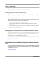
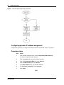
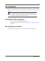
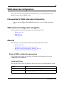
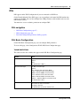
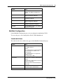
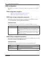
Ethernet WAN configuration procedures
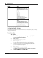
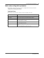
The following task flow shows the sequence of procedures to perform to configure the Ethernet
WAN.
Configuration Guide
16
WAN configuration
Figure 1 Ethernet WAN configuration procedures
Configuring dynamic IP address assignment
Complete this procedure to configure the Ethernet WAN for dynamic IP address assignment.
Procedure steps
Step
Action
1
From the BSG navigation pane, select Configuration, WAN, Ethernet.
The WAN Configuration pane appears.
2
From the Interface list, select the required interface.
3
From the Encapsulation Mode list, select Ethernet.
4
From the MAC Cloning list, select Enable.
5
In the MAC Address field, type the MAC Address.
6
For IP Address Assignment, select Dynamic.
7
Click Apply.
End
NN47928-500
WAN configuration
17
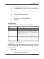
Variable definitions
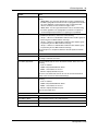
The following table describes the variables and values for configuring Ethernet WAN.
Variable
Value
Interface
Select an Interface to be configured.
Encapsulation Mode
Set the encapsulation mode to Ethernet. The WAN interface operates as a
normal Ethernet interface.
MAC Cloning
Select the MAC cloning status.
Enable - the BSG uses the configured MAC address as the source of
Ethernet frames instead of the MAC address of the BSG WAN port.
Disable - disables MAC Cloning.
You can enable MAC cloning only if the Encapsulation Mode is Ethernet.
The default value is Disable.
MAC Address
Type the MAC address, if the MAC cloning is enabled.
IP Address Assignment
Select Dynamic for the system to assign the IP address for the specified
VLAN from the Dynamic Host Configuration Protocol (DHCP) server.
Configuring manual IP address assignment
Complete this procedure to configure the Ethernet WAN for manual IP address assignment. The IP
Address Assignment field has a default value of Manual.
Procedure steps
Step
Action
1
From the BSG navigation pane, select Configuration, WAN, Ethernet.
The WAN Configuration pane appears.
2
From the Interface list, select the required interface.
3
From the Encapsulation Mode list, select Ethernet.
4
In the WAN IP Address field, type the IP address.
5
In the Subnet Mask field, type the subnet mask.
6
In the Gateway IP Address field, type the Gateway IP Address.
7
In the Primary DNS field, type the Primary Domain Name System (DNS) IP
address.
8
In the Secondary DNS field, type the Secondary DNS IP address.
9
Click Apply.
End
Configuration Guide
18
WAN configuration
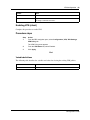
Variable definitions
The following table describes the variables and values for configuring Ethernet WAN.
Variable
Value
Interface
Select an Interface to be configured.
Encapsulation Mode
Set the encapsulation mode to Ethernet. The WAN interface operates as a
normal Ethernet interface.
WAN IP Address
Type the WAN IP address, if the IP Address Assignment is manual.
Subnet Mask
Type the subnet mask, if the IP Address Assignment is manual.
Gateway IP Address
Type the gateway IP Address, if the IP Address Assignment is manual.
Configurable
Primary DNS
Type the primary DNS server IP address, if the IP Address Assignment is
manual.
Secondary DNS
Type the secondary DNS server IP address, if the IP Address Assignment
is manual.
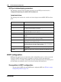
Configuring the uplink rate limit
Certain downstream devices cannot handle the high traffic rate from the BSG. This feature allows
you to limit the rate of traffic sent on the WAN interface. You should limit the uplink speed only if
your WAN bandwidth is less than 100 Mbps and the device in front of the BSG does not support
pause frame.
Complete this procedure to configure the uplink rate limit.
Procedure steps
Step
Action
1
From the BSG navigation pane, select Configuration, WAN, Rate Limit.
The Rate Limit Configuration pane appears.
2
From the Rate Limit Status list, select Enabled.
3
In the Uplink Rate Limit field, type the uplink rate limit provided by your ISP.
4
Click Apply.
End
NN47928-500
WAN configuration
19
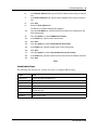
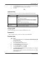
Variable definitions
The following table describes the variables and values for configuring the uplink rate limit.
Variable
Value
Rate Limit Status
Select the rate limit status.
• Enabled - enables uplink rate limiting feature
• Disabled - disables uplink rate limiting feature
The default value is Disabled.
Uplink Rate Limit
Specifies the maximum uplink rate limit over the WAN interface (in bps).
The range is 100,000 to 100,000,000 bps.
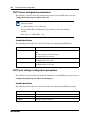
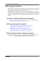
PPPoE WAN configuration
This section describes PPPoE WAN configuration. You can configure PPPoE WAN if you are
connected to a BSG8ew or BSG12ew.
Prerequisites for WAN configuration
•
You must have SYSTEM - READ WRITE permission.
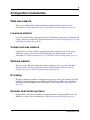
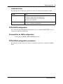
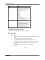
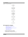
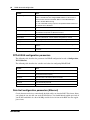
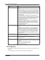
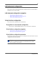
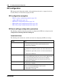
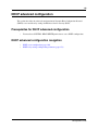
PPPoE WAN configuration procedures
The following task flow shows the sequence of procedures to perform to configure the PPPoE
WAN.
Configuration Guide
20
WAN configuration
Figure 2 PPPoE WAN configuration procedures
Configuring the PPPoE WAN
Complete this procedure to configure the PPPoE WAN.
Procedure steps
Step
Action
1
From the BSG navigation pane, select Configuration, WAN, Ethernet.
The WAN Configuration pane appears.
2
From the Interface list, select the required interface.
3
From the Encapsulation Mode list, select PPPoE.
4
In the ISP Name field, type the Internet Service Provider name.
5
In the User Name field, type the PPPoE user name supplied by your ISP.
6
In the Password field, type the PPPoE password supplied by your ISP.
7
In the Host Name field, type the Host name.
8
Click Apply.
End
NN47928-500
WAN configuration
21
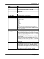
Variable definitions
The following table describes the variables and values for configuring PPPoE WAN.
Variable
Value
Interface
Select an Interface to be configured.
Encapsulation Mode
Set the encapsulation mode PPPoE. The WAN interface operates as a
Point-to-Point Protocol (PPP).
ISP Name
Type the name of the Internet Service Provider.
User Name
Type the PPPoE user name.
Password
Type the PPPoE password.
Host Name
Type the host name.
Configuring the uplink rate limit
Certain downstream devices cannot handle the high traffic rate from the BSG. This feature allows
you to limit the rate of traffic sent on the WAN interface. You should limit the uplink speed only if
your WAN bandwidth is less than 100 Mbps and the device in front of the BSG does not support
pause frame.
Complete this procedure to configure the uplink rate limit.
Procedure steps
Step
Action
1
From the BSG navigation pane, select Configuration, WAN, Rate Limit.
The Rate Limit Configuration pane appears.
2
From the Rate Limit Status list, select Enabled.
3
In the Uplink Rate Limit field, type the uplink rate limit provided by your ISP.
4
Click Apply.
End
Variable definitions
The following table describes the variables and values to configure the uplink rate limit.
Variable
Value
Rate Limit Status
Select the rate limit status:
• Enabled - enables uplink rate limiting feature
• Disabled - disables uplink rate limiting feature
The default value is Disabled.
Uplink Rate Limit
Specifies the maximum uplink rate limit over the WAN interface (in bps).
The range is 100,000 to 100,000,000 bps.
Configuration Guide
22
WAN configuration
NN47928-500
WAN configuration
23
DSL
DSL appears under WAN configuration if you are connected to a BSG12aw.
On the Digital Subscribe Line (DSL) pages you can configure and control the DSL modem that
connects to the BSG. You can also configure the ATM parameters of the modem and access the
DSL modem statistics.
Prerequisites for DSL configuration
•
You must have access read/write permission to configure DSL.
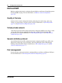
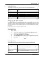
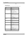
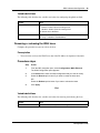
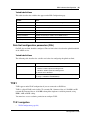
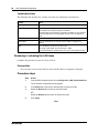
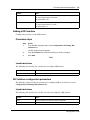
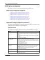
DSL configuration procedures
The following task flow shows the sequence of procedures to perform to configure DSL.
Figure 3 DSL configuration procedures
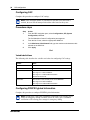
Configuring DSL
Complete this procedure to configure DSL.
Procedure steps
Step
Action
1
From the BSG navigation pane, select Configuration, WAN, DSL.
The Basic Configuration pane appears.
2
In the VPI / VCI field, type the VPI / VCI values.
Configuration Guide
24
WAN configuration
Your service provider provides you with these values when you set up your
account.
3
In the MRU field, type the value 1492.
4
Click Add.
5
Select the IP Configuration tab.
The PPP Configuration pane appears.
6
In the User Name field, type the User Name provided by your service provider.
7
In the Password field, type the Password provided by your service provider.
8
Click Apply.
End
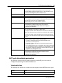
Variable definitions
This table describes the variables to configure DSL.
Variable
Value
VPI / VCI
The Virtual Path Identifier/Virtual Channel Identifier (VPI/VCI) used by the
DSL modem to make a connection.
The range is 0 to 255.
The default value for VPI is 8 and VCI is 35. These default values do not
appear until you add a configuration.
MRU
The Maximum Receivable Unit (MRU) value. MRU specifies the maximum
number of bytes received on a link. The default value is 1492.
User Name
The user name for the specified PPP interface, used for authentication.
The user name is provided by your service provider.
Password
The password for the specified PPP interface, used for authentication. The
password is provided by your service provider.
Configuring the uplink rate limit
Complete this procedure to enable the uplink rate limit. The rate limit value is based on the uplink
bandwidth of the ADSL service.
Procedure steps
Step
Action
1
From the BSG navigation pane, select Configuration, WAN, Rate Limit.
The Rate Limit Configuration pane appears.
NN47928-500
2
From the Rate Limit Status list, select Enabled.
3
In the Uplink Rate Limit field, type the uplink rate limit provided by your ISP.
4
Click Apply.
WAN configuration
25
End
Variable definitions
The following table describes the variables and values to configure the uplink rate limit.
Variable
Value
Rate Limit Status
Select the rate limit status:
• Enabled - enables uplink rate limiting feature
• Disabled - disables uplink rate limiting feature
The default value is Disabled.
Uplink Rate Limit
Specifies the maximum uplink rate limit over the WAN interface (in bps).
The range is 100,000 to 100,000,000 bps.
Configuration Guide
26
WAN configuration
T1/E1
T1/E1 appears under WAN configuration if you are connected to a BSG12tw.
T1/E1 is a digital WAN carrier facility. T1 transmits DS-1 formatted data at 1.544 MB/s and E1
transmits E1 formatted data at 2.048 MB/s through the telephone e-switching network.
Prerequisites for T1/E1 configuration
•
You must have access read/write permission to configure T1/E1.
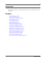
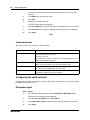
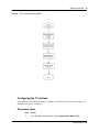
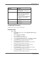
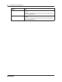
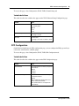
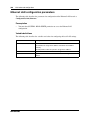
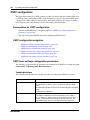
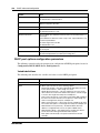
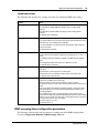
T1/E1 configuration procedures
The following task flow shows the sequence of procedures to perform to configure T1/E1.
NN47928-500
WAN configuration
27
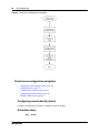
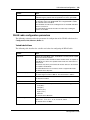
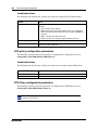
Figure 4 T1/E1 configuration procedures
Configuring the T1 interface
If your BSG is located in North America, configure the T1 interface. This procedure guides you
through setting up one T1 interface.
Procedure steps
Step
Action
1
From the BSG navigation pane, select Configuration, WAN, T1/E1.
Configuration Guide
28
WAN configuration
The T1/E1 Configuration pane appears.
2
Select interface 1.
The Interface Type field defaults to T1.
3
From the Framing list, select ESF or SF.
The framing you set here must agree with the framing used by the peer.
4
From the Line Mode list, select CSU or DSU.
This setting depends upon the distance between the devices on either end of
the T1 line. For shorter distances, use DSU. For longer distances, use CSU.
This information should be provided by your service provider.
5
From the LineBuildOut list, select 0, -7.5, -15, or -22.5.
You can configure LineBuildOut if Line Mode is CSU.
You should contact your service provider for proper settings for the:
6
•
type of framing
•
line coding
•
line mode
•
line build out
•
line length
•
clock source
From the Line Length list, select the line length.
You can configure line length when Line Mode is DSU. This setting depends
upon the length of the cable connecting the devices on each end of a T1 line.
7
From the Transmit ClockSource list, select Loop Timing.
When you select Loop Timing, the remote end provides the clock source. Check
with your service provider.
8
Click Apply.
End
NN47928-500
WAN configuration
29
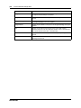
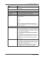
Variable definitions
This table describes the variables used to configure the T1/E1 interface.
Variable
Value
Interface
The T1/E1 controller.
Framing
The Framing Type for the T1/E1 data line.
Options for T1:
Extended Super Frame (ESF)— 24
consecutive 193-bit frames of data.
Super Frame (SF)—12 consecutive
193-bits of data.
Unframed—the non signaling or unframed
framing format is a simplified version of
the T1 super frame.
The default value is ESF.
Line Mode
The Line Mode.
Options:
Channel Service Unit (CSU)—select if
cable length is equal to or more than 655
feet.
Data Service Unit (DSU)—select if cable
length is less than 655 feet.
The default value is CSU.
LineBuildOut
The level of attentuation (in decibels)
required for the devices on each end of a
T1 line to communicate. Options are:
0 db
-7.5 db
-15 db
-22.5 db
You can configure this field only for T1
CSU mode.
Configuration Guide
30
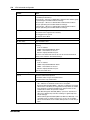
WAN configuration
Variable
Value
Line Length
The Line Length value.
Line Length refers to the length of the
cable (in feet) that connects the devices
on each end of a T1 line.
Options:
0 - 133
134 - 266
267 - 399
400 - 533
534 - 655
The default value is 0 - 133.
You can configure the line length only
when the Line Mode is DSU.
Transmit ClockSource
The clock source.
Options:
Local Timing—A local clock source is
used or an external clock is attached to
the box containing the interface.
Loop Timing—Recovered received clock
is used to transmit the clock.
The default value is Loop Timing.
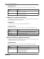
Configuring the E1 interface
If your BSG is located in Europe, configure the E1 interface. This procedure guides you through
setting up one E1 interface.
Procedure steps
Step
Action
1
From the BSG navigation pane, select Configuration, WAN, T1/E1.
The T1/E1 Configuration pane appears.
2
Select interface 1.
3
From the Interface Type list, select E1.
4
Reboot the system.
You must reboot the system before setting up the E1 parameters.
5
From the BSG navigation pane, select Configuration, WAN, T1/E1.
The T1/E1 Configuration pane appears.
6
Select interface 1.
7
From the Framing list, select E1 or E1CRC.
The framing you set here must agree with the framing used by the peer.
8
NN47928-500
From the Line Mode list, select CSU or DSU.
WAN configuration
31
This setting depends upon the distance between the devices on either end of
the E1 line. For shorter distances, use DSU. For longer distances, use CSU.
This information should be provided by your service provider.
9
From the Line Length list, select the line length.
You can configure line length only when Line Mode is DSU. This setting
depends upon the length of the cable connecting the devices on each end of a
E1 line.
10
From the Transmit ClockSource list, select Loop Timing.
When you select Loop Timing, the remote end provides the clock source. Check
with your service provider.
11
Click Apply.
End
Variable definitions
This table describes the variables used to configure the T1/E1 interface.
Variable
Value
Interface
The T1/E1 controller.
Interface Type
The interface type for the given interface.
Options:
T1
E1
The default value is T1.
If you change the interface type, you must
reboot the system before configuring the
remaining parameters.
Framing
The Framing Type for the T1/E1 data line.
Options for E1:
E1—a single E1 frame consists of 256
bits, grouped into 32 octets or time slots.
The timeslots are numbered 0 to 31.
E1CRC
The default value is E1CRC.
Line Mode
The Line Mode.
Options:
Channel Service Unit (CSU)—select if
cable length is equal to or more than 655
feet.
Data Service Unit (DSU)—select if cable
length is less than 655 feet.
The default value is CSU.
Configuration Guide
32
WAN configuration
Variable
Value
Line Length
The Line Length value.
Line Length refers to the length of the
cable (in feet) that connects the devices
on each end of an E1 line.
Options:
0 - 133
134 - 266
267 - 399
400 - 533
534 - 655
The default value is 0 - 133.
You can configure the line length only
when the Line Mode is DSU.
Transmit ClockSource
The clock source.
Options:
Local Timing—A local clock source is
used or an external clock is attached to
the box containing the interface.
Loop Timing—Recovered received clock
is used to transmit the clock.
The default value is Loop Timing.
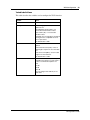
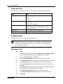
Configuring the channel groups
Complete this procedure to configure the T1/E1 channel groups.
Procedure steps
Step
Action
1
From the BSG navigation pane, select Configuration, WAN, T1/E1, Channel
Group.
The T1/E1 Channel Group Configuration pane appears.
2
In the Channel Group Index field, type the channel group index.
The Channel Group Index identifies a group of channels on the T1 interface.
3
In the Time Slot field, type the channel number or the range of channel
numbers.
This channel numbers are provided by your service provider.
4
Click Add.
End
NN47928-500
WAN configuration
33
Variable definitions
This table describes the variables that appear on the T1/E1 Channel Group Configuration page.
Variable
Value
Channel Group
This identifies an instance of channel
grouping on a T1 or E1 interface. The
format is Serialx/y where x is either 1 for
port 1 or 2 for port 2 and y is the Channel
Group Index.
Channel Group Index
The Channel Group Index. This identifies
a grouping of channels on the T1
interface.
The range is 1to 64.
Interface
This identifies which of the two T1/E1
interfaces on the BSG. Possible values
are t1e1-1 or t1e1-2.
Time Slot
The time slots.
The range is 1to 24 for T1 and 2 to 32 for
E1.
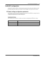
Configuring the PPP interface
Complete this procedure to configure the PPP interface.
Procedure steps
Step
Action
1
From the BSG navigation pane, select Configuration, WAN, T1/E1, PPP
Configuration.
The PPP Configuration pane appears.
2
From the Serial Interface list, select Serial1/1.
3
From the Authentication Required list, select YES or NO.
Your service provider will notify you if authentication is required.
4
From the Server/Client list, select Server or Client.
This is available only if authentication is required.
5
In the User Name field, type the user name.
If you selected Client, type the BSG user name.
If you selected Server, type the peer user name.
6
In the Password field, type the password.
If you selected Client, type the BSG password.
If you selected Server, type the peer password.
7
From the Link Type list, select Public.
8
Click Apply.
Configuration Guide
34
WAN configuration
End
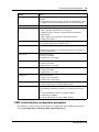
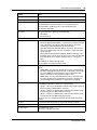
Variable definition
This table describes the variables that appear on the PPP Configuration page.
Variable
Value
Serial Interface
The serial Interface on which you layer the
PPP interface.
Authentication Required
Select whether authentication is required
for the PPP interface.
Options:
YES—enables the Server/Client, User
Name, and Password fields.
NO—authentication is not required for
PPP interface.
Server/Client
Select whether the Server or Client is
required for authentication. This field is
available only if authentication is required.
Options:
Server - authenticates the peer at the time
of negotiation.
Client - authenticated by the peer router at
the time of negotiation.
User Name
The User Name required for the Server or
Client that requires authentication.
This field is available only if authentication
is required.
Password
The password for the specified user.
This field is available only if authentication
is required.
Keep Alive
Enter the Keep Alive Time Out value in
seconds. This denotes that the connection
will be lost if no Echo response packet is
received within the timeout value. The
default value is 10.
Link Type
The PPP link type.
Options:
Public—adds the default route for the PPP
interface.
Private—no default route is added for the
PPP interface.
The default value is Private.
MTU
Specifies the Maximum Transmission unit.
Maximum value is 1500.
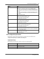
The configuration table displays the following additional information:
NN47928-500
WAN configuration
Field Name
Description
PPP Interface
Read-only field. Specifies the name of the
PPP interface and the serial interface over
which it is layered.
Bundle
Specifies whether the PPP interface can be
bundled to form a multilink or not. Options are
Yes and No. Select Yes to bundle the PPP
interface to form a multilink. Select No to
unbundle a PPP interface.
• When a PPP interface is bundled to form
a multilink, you cannot configure the user
name and password for that PPP
interface.
Bundle With
Lists the available Multilink interfaces. Select
the required multilink interface for a specific
PPP interface.
Status
Read-only field to indicate the admin status of
the PPP interface.
35
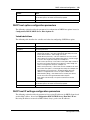
Configuring IP information
Complete this procedure to configure IP information.
Procedure steps
Step
Action
1
From the BSG navigation pane, select Configuration, WAN, T1/E1, IP
Configuration.
The IP Configuration pane appears.
2
From the PPP/MP list, select PPP1.
This is the PPP interface you just created.
3
From the IP Address Assignment buttons, select Manual or Dynamic.
4
In the IP Address field, type the IP address of PPP interface.
Set this field if IP Address Assignment is Manual.
5
In the Subnet Mask field, type the subnet mask of the IP address.
Set this field if IP Address Assignment is Manual.
6
In the Peer IP Address field, type the IP address of the peer.
Set this field if IP Address Assignment is Manual.
7
In the Primary DNS field, type the primary DNS server IP address.
Set this field if IP Address Assignment is Manual.
8
In the Secondary DNS field, type the secondary DNS server IP address.
Set this field if IP Address Assignment is Manual.
Configuration Guide
36
WAN configuration
9
*In the Peer DNS field, type the DNS server IP address of the peer.
Set this field if IP Address Assignment is Manual.
10
Click Apply.
End
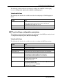
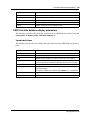
Variable definitions
This table describes the variables that appear on the IP Configuration page.
Variable
Value
PPP/MP Interface
The PPP/Multilink interface for which the
IP address is configured.
IP Address Assignment
The IP address assignment mode.
Options:
Dynamic—obtains the IP address
dynamically from the peer. Manual
configuration is not required.
Manual—configure the IP address
manually. Manually configure the IP
Address, Subnet Mask, and Peer IP
Address fields.
IP Address
The IP address of the PPP/Multilink
interface, if IP Address Assignment is
Manual.
Subnet Mask
The Subnet Mask for the IP address, if IP
Address Assignment is Manual.
Peer IP Address
The Peer IP address, if IP Address
Assignment is Manual.
Primary DNS Server
The Primary DNS server IP address, if IP
Address Assignment is Manual.
Secondary DNS Server
The Secondary DNS server IP address, if
IP Address Assignment is Manual.
Peer DNS*
The Peer DNS server IP address, if IP
Address Assignment is Manual.
* The Peer DNS should only be configured if this BSG will act as the PPP server. In this case only,
when a PPP is established between this BSG and the other peer which obtains its IP address and
DNS dynamically, the peer DNS configured on this BSG will be assigned as the primary DNS on
the peer.
NN47928-500
37
VLAN configuration
This section describes the procedures for configuring the virtual local area network (VLAN)
settings for the Business Service Gateway (BSG).
VLAN1 is the default VLAN. The BSG provides VLAN1 as a fully functioning VLAN using all
eight ports.
Prerequisites to VLAN configuration
•
You must have SYSTEM - READ WRITE, L2 - READ WRITE, and L3 - READ WRITE
permission to access the information on the VLAN configuration panels.
VLAN configuration procedures
The following task flow shows the sequence of procedures to perform to configure a VLAN.
Configuration Guide
38
VLAN configuration
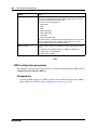
Figure 5 VLAN configuration procedures
VLAN configuration navigation
•
•
•
Creating a new VLAN (page 38)
Configuring the virtual interface (page 39)
Configuring DHCP pool settings (page 40)
Creating a new VLAN
Complete this procedure to create a new VLAN.
Procedure steps
Step
Action
1
From the BSG navigation pane, select Configuration, VLAN Setup, Static
VLAN tab.
The Static VLAN Configuration pane appears.
2
NN47928-500
In the VLAN ID field, type the VLAN ID.
VLAN configuration
39
3
In the VLAN Name field, type the VLAN name.
4
In the Member Ports field, type the numbers and/or ranges of member ports.
5
In the Untagged Ports field, type the numbers and/or ranges of untagged ports.
6
Click Add.
7
From the BSG navigation pane, select Configuration, VLAN, Setup, Port
Setting tab.
The VLAN Port Settings pane appears.
8
Select the port setting that you want to modify.
This is the list of member ports you added to the new VLAN in step 4.
9
In the PVID field, type the port VLAN ID.
Use the same value you entered for VLAN ID in step 2.
10
Click Apply.
End
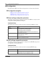
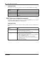
Variable definitions
The following table describes the variables and values for creating a VLAN.
Variable
Value
VLAN ID
Type a unique VLAN ID that you want to configure as a static VLAN.
VLAN Name
Type the VLAN name.
Member Ports
Type the member port number list for a VLAN.
Member ports represent the set of ports permanently assigned to the
VLAN egress list. Frames that belong to the specified VLAN are forwarded
on the ports in the egress list.
Enter a comma separated list of ports or port ranges. For example, 1-6, 9,
11.
Untagged Ports
Type the untagged port number list for a VLAN.
Enter a comma separated list of ports or port ranges. For example, 1-6, 9,
11.
The Untagged Ports list must be a subset of the Member Ports.
PVID
Type the port VLAN ID.
Configuring the virtual interface
Complete this procedure to configure the virtual interface. You must configure a virtual interface
if hosts on the new VLAN need to communicate with other hosts on other VLANs or on the WAN.
Procedure steps
Step
Action
1
From the BSG navigation pane, select Configuration, LAN, Virtual Interfaces.
The IP Address Configuration pane appears.
Configuration Guide
40
VLAN configuration
2
In the VLAN ID field, type the VLAN ID.
3
In the IP Address field, type the IP address.
4
In the Subnet Mask field, type the subnet mask address.
5
In the MTU field, type the MTU value.
6
Click Add.
End
Variable definitions
The following table describes the variables and values for configuring the virtual interface.
Variable
Value
VLAN ID
Type the VLAN identifier.
IP Address Assignment
Select the IP address assignment mode.
Select Manual to manually assign the IP address.
Select Dynamic for the System to assign the IP address for the specified
VLAN from Dynamic Host Configuration Protocol (DHCP) server
configured in BSG.
IP Address
Type the IP address, if the IP address assignment is Manual.
Subnet Mask
Type the subnet mask for the LAN, if the IP address assignment is
Manual.
MTU
Type the Maximum Transmission Unit value.
The range is 90 to 9902. The default value is 1500.
If using Fast Ethernet, the MTU frame size must not be larger than 1522.
Configuring DHCP pool settings
Complete this procedure to configure DHCP pool settings. You must configure DHCP pool
settings if hosts on the new VLAN need to communicate with other hosts on other VLANs or on
the WAN.
Procedure steps
Step
Action
1
From the BSG navigation pane, select Configuration, DHCP, DHCP Server,
Pool Settings tab.
The DHCP Pool Settings pane appears.
2
In the DHCP Pool Id field, type the pool ID.
3
In the DHCP Pool Name field, type the name of the pool.
4
In the Subnet Pool field, type the subnet pool IP address.
Use the same value you entered for Subnet Mask when you configured the
virtual interface.
5
NN47928-500
In the Network Mask field, type the network mask IP address.
VLAN configuration
41
6
In the Start IP Address field, type the first IP address of the range you want to
use.
7
In the End IP Address field, type the last IP address of the range you want to
use.
8
Click Add.
9
Select the Pool Options tab.
The DHCP Pool Option Settings pane appears.
10
From the Pool Name list, select the DHCP Pool Name you configured on the
Pool Settings pane.
11
From the Option list, select NetMask (IP Format).
12
In the Value field, type the client subnet mask.
13
Click Add.
14
From the Option list, select Default Router (IP Format).
15
In the Value field, type the default router for the client subnet.
16
Click Add.
17
From the Option list, select Domain Name Server (IP Format).
18
In the Value field, type the domain name server used for IP address resolution.
19
Click Add.
End
Variable definitions
The following table describes the variables and values to configure DHCP settings.
Variable
Value
DHCP Pool Id
Type the pool ID for the DHCP pool.
DHCP Pool Name
Type the pool name for the DHCP pool.
Subnet Pool
Type the subnet of the IP address in the pool.
Network Mask
Type the subnet mask of the IP address in the pool.
Start IP Address
Type the first IP address in the pool. The DHCP server uses this IP address for
dynamic allocation.
End IP Address
Type the last IP address in the pool.
Pool Name
Select the pool name.
Configuration Guide
42
VLAN configuration
Variable
Value
Option
The DHCP option. Select one of the following options:
• Netmask (IP Format) – the client subnet mask (RFC 950). The code for the
subnet mask is 1 and its length is 4 octets.
• Default Router (IP format) – a list of IP addresses for routers on the client
subnet. The code for the default router option is 3 and its length is 4 octets. The
length must always be a multiple of 4.
• Timer servers (IP format) – a list of time servers (RFC 868) available to the
client. The code for the time server option is 4 and its length is 4 octets. The
length must always be a multiple of 4.
• Name server (IP format) – a list of name servers available to the client. The
code for this option is 4. The length must always be a multiple of 4.
• Domain Name Server (IP format) – the Domain Name Server IP address is
configured and is sent as an option in DHCP offers.
• Domain Name (String) – this domain name is used by the client to resolve host
names through the Domain Name System.
• Enter option code manually – the option code must be entered manually.
Option Code
For the Enter option code manually option, you must enter the code.
For all other options, this field is automatically updated.
Value
Type the option value.
NN47928-500
43
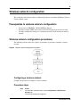
Wireless network configuration
This section describes the procedures to configure the wireless network for the Business Services
Gateway (BSG) system.
Prerequisites to wireless network configuration
•
•
•
You must have WIRELESS - READ WRITE permission.
You must configure DHCP pool settings for the VLAN used for the wireless network.
You must configure the radio port as a member port of the VLAN used for the wireless
network.
Wireless network configuration procedures
The following task flow shows the sequence of procedures to perform to configure a wireless
network.
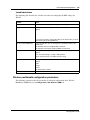
Figure 6 Wireless network configuration procedures
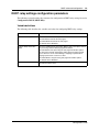
Configuring a wireless network
Complete this procedure to configure a wireless network.
Procedure steps
Step
Action
1
From the BSG navigation pane, select Configuration, LAN, Wireless,
Security tab.
The Security Settings pane appears.
Configuration Guide
44
Wireless network configuration
2
From the list of security settings, select the first default SSID.
The first SSID is enabled.
3
From the Authentication Type list, choose an authentication type.
4
From the Pre-Authentication Status list, select Enabled or Disabled.
This field is available only if Authentication Type is set to WPA, WPA2,
WPA-WPA2-Mixed, or Open1x.
5
From the Pre Shared Key Type list, select HEX or ASCII.
This field is available only if Authentication Type is set to WPA-PSK,
WPA2-PSK, or WPA-WPA2-PSK-Mixed.
6
In the Pre Shared Key field, type the pre-shared key value.
This field is available only if Authentication Type is set to WPA-PSK,
WPA2-PSK, or WPA-WPA2-PSK-Mixed.
7
From the Cipher Suite list, select the cipher used for data encryption.
This field is available only if Authentication Type is set to WPA, WPA2,
WPA-WPA2-Mixed, WPA-PSK, WPA2-PSK, or WPA-WPA2-PSK-Mixed.
8
In the PMK SA Lifetime field, type the maximum lifetime of a PMK in the PMK
cache.
This field is available only if Authentication Type is set to WPA, WPA2,
WPA-WPA2-Mixed, WPA-PSK, WPA2-PSK, WPA-WPA2-PSK-Mixed, or
Open1x.
9
Click Apply.
10
Select the Basic Settings tab.
The Basic WLAN Page pane appears.
11
From the Access Point list, select Enabled.
12
From the Country Code list, select the appropriate country.
13
From the Radio Mode list, select Mixed.
14
Click Apply.
End
NN47928-500
Wireless network configuration
45
Variable definitions
The following table describes the variables and values for configuring the wireless network.
Variable
Value
Select
Select the first default SSID to configure security settings.
Authentication Type
Specifies the method used to authenticate wireless clients. Select
the Authentication Type for stations that use this SSID.
Select Open if authentication is not required.
Select Open1X to use 802.1x authentication.
Select Shared to use a shared key.
Select WPA, WPA2, or WPA-WPA2-Mixed if Radius server is used
for authentication.
Select WPA-PSK, WPA2-PSK, or WPA-WPA2-PSK-Mixed if
authentication uses a preshared key.
Pre-Authentication
Specifies the preauthentication status.
Select Enabled to enable the Robust Security Networks Association
(RSNA) pre authentication on this entity. Stations authenticate to
different APs, if present, but associate to a single AP.
Select Disabled to disable the RSNA pre authentication. Stations
authenticate to a single AP.
This field is available only if Authentication Type is set to WPA,
WPA2, or WPA-WPA2-Mixed.
Pre Shared Key Type
Specifies the preshared key type, either Hex or ASCII.
If you select Hex, you must provide a Hex key in the PreSharedKey
field.
If you select ASCII, you must provide ASCII characters in the
PreSharedKey field.
The pass-phrase is an ASCII character string, whereas the manual
key is a string of hexadecimal numbers.
This option is enabled only when the authentication type is
WPA-PSK, WPA2-PSK, or WPA-WPA2-PSK-Mixed.
Pre Shared Key
Specifies the preshared key.
If the PreSharedKey (PSK) Type is Hex, the PSK length must be 64.
If the PSK Type is ASCII, the PSK length ranges between 8 and 63.
This option is enabled only when the authentication type is
WPA-PSK, WPA2-PSK, or WPA-WPA2-PSK-Mixed.
Configuration Guide
46
Wireless network configuration
Variable
Value
Cipher Suite
Specifies the required pair wise cipher and is used for data
encryption. It consists of an organizationally unique identifier (OUI)
(the first 3 octets) and a cipher suite identifier (the last octet).
Select one of the following options:
• AES-CCMP
• TKIP
• WEP
• AES-CCMP-TKIP
• AES-CCMP-WEP
• TKIP-WEP
• AES-CCMP-TKIP-WEP.
This field is used in conjunction with the Authentication Type. If you
select WPA for Authentication Type, the BSG supports TKIP. If you
select WPA2, the BSG supports AES-COMP and TKIP.
PMK SA Lifetime
Type the Pair wise Master Key (PMK) SA (Security Association)
Lifetime value.
This represents the maximum lifetime of a PMK in the PMK cache.
The valid range is 1 to 4294967295.
The default value is 43200.
Access Point
The Access Point represents the status of radio in the BSG.
Select Enabled to activate the radio.
Select Disabled to deactivate the radio.
You must select a country code before you enable the access point.
Country Code
Select the required country code.
A country code is required to set up the proper regulatory restrictions
for channel availability and transmission power.
You must disable the radio (Access Point) before you set the country
code.
Radio Mode
Select the required radio mode. Select one of the following options:
• 802.11b - For a network with all 802.11b clients, select 802.11b
mode. The BSG has a single 802.11b radio.
• 802.11g - For a network with all 802.11g clients, select the
802.11g mode.
• Mixed - Select Mixed Mode for a network with many 802.11g
devices with a lesser population of 802.11b clients. Performance
degradation can occur.
NN47928-500
47
SIP configuration
This section describes the procedures to configure SIP for the Business Services Gateway (BSG)
system.
Note: You should configure the emergency number (for example, 911) before
you use the SIP server. This ensures that an emergency call originating on your
system reaches its destination if the SIP server becomes unavailable. To configure
the emergency number, see Configuring FXO (page 52).
Prerequisites to SIP configuration
•
•
You must have VOICE - READ WRITE permission.
The Internal SIP Server must be enabled. See Central SIP server configuration parameters
(page 179).
SIP configuration procedures
The following task flow shows the sequence of procedures to perform to configure SIP.
Configuration Guide
48
SIP configuration
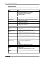
Figure 7 SIP configuration procedures
SIP configuration navigation
•
•
•
•
•
Configuring SIP system settings (page 48)
Configuring CAC (page 50)
Configuring FXS/FXO global information (page 50)
Variable definitions (page 51)
Configuring FXO (page 52)
Configuring SIP system settings
Complete this procedure to configure SIP system settings.
NN47928-500
SIP configuration
49
Procedure steps
Step
Action
1
From the BSG navigation pane, select Configuration, SIP, System
Configuration.
The Central SIP Server Configuration pane appears.
2
In the Managed Domain Name field, type the domain name of your voice
service provider.
3
In the Central SIP Server Address field, type the central SIP server IP address.
4
From the Transport list, select the transport protocol to use for the port.
5
In the Port field, type the port number to use for the transport protocol.
6
In the Poll Interval field, type the number of seconds for the interval time.
7
In the Poll Retries field, type the number of times the server tries to connect.
8
Click Apply.
End
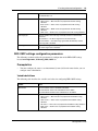
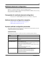
Variable definitions
The following table describes the variables and values for configuring SIP system settings.
Variable
Value
Managed Domain Name
Type the domain name of the SIP server.
You can also type the IP address of the SIP server in this field.
The default name is mydomain.com.
Central SIP Server Address
Type the IP address of the central SIP server.
This field is mandatory.
Transport
Select the required transport protocol for SIP. Select one of the following
options:
• User Datagram Protocol (UDP) - the transport protocol is UDP.
• Transmission Control Protocol (TCP) - the transport protocol is TCP.
• Transport Layer Security (TLS) - the transport protocol is TLS.
The default value is UDP.
Port
Type the port number for the transport protocol.
The value ranges from 1 to 65535.
The default value is 5060. This default value appears only after the Central
SIP Server is configured.
Poll Interval
Type the SIP poll interval value in seconds.
The value ranges from 10 to 600 seconds. The default value is 30
seconds.
Poll Retries
Type the poll retry value.
The value ranges from 1 to 10.
The default value is 2.
Configuration Guide
50
SIP configuration
Configuring CAC
Complete this procedure to configure CAC settings.
Note: If the maximum number of simultaneous SIP calls across the WAN is
reached, the next SIP call attempt fails and the caller hears fast busy tone.
Procedure steps
Step
Action
1
From the BSG navigation pane, select Configuration, SIP, System
Configuration, CAC tab.
The Call Admission Control Configuration pane appears.
2
From the list of rows, select the appropriate WAN link.
3
In the Maximum Calls Allowed field, type the maximum simultaneous calls
allowed on the WAN link.
4
Click Apply.
End
Variable definitions
The following table describes the variables and values for configuring CAC settings.
Variable
Value
Select
Select a row.
WAN Link
Select the required WAN link.
Maximum Calls Allowed
The maximum simultaneous calls allowed on each WAN link.
The range is 1 to 50 for BSG8ew.
The range is 1 to 100 for BSG12ew/aw/tw.
The default value is 20.
Active Calls
The number of calls currently active on the WAN link.
The range is 0 to 50 for BSG8ew.
The range is 0 to 100 for BSG12ew/aw/tw.
Configuring FXS/FXO global information
Complete this procedure to configure FXS/FXO global information.
Note: For BSG8ew, FXS2 (port 2) maintains connection to FXO during power
outage for emergency dialing. For BSG12ew/aw/tw, FXS1 (port 1) maintains
connection to FXO during power outage for emergency dialing.
NN47928-500
SIP configuration
51
Procedure steps
Step
Action
1
From the BSG navigation pane, select Configuration, SIP, FXO/FXS.
The Global Configuration pane appears.
2
From the Country Code list, select the country code.
3
Click Apply.
End
Variable definitions
The following table describes the variables and values for configuring FXS/FXO global
information.
Variable
Value
Country Code
The country code.
The default value is Canada/US.
Configuring FXS
Complete this procedure to configure FXS information.
Procedure steps
Step
Action
1
From the BSG navigation pane, select Configuration, SIP, FXO/FXS, FXS tab.
The Foreign Exchange Subscriber (FXS) Configuration pane appears.
2
From the FXS Channel list, select Line 1.
3
Select the Channel Enable check box to enable the channel.
4
In the Channel Number field, type the channel number.
5
In the Password field, type the password to access the FXS channel.
6
Click Apply.
7
From the FXS Channel list, select Line 2.
8
Select the Channel Enable check box to enable the channel.
9
In the Channel Number field, type the channel number.
10
In the Password field, type the password to access the FXS channel.
11
Click Apply.
End
Configuration Guide
52
SIP configuration
Variable definitions
The following table describes the variables and values for configuring FXS information.
Variable
Value
FXS Channel
Select the required FXS channel. Select one of the following
options:
• Line1
• Line2
Channel Enable
Select this check box to enable the administrative status of the
FXS channel.
The default value is disabled.
Channel Number
Type the FXS channel number.
The maximum length of the channel number is 31 digits.
This field is mandatory.
Display Name
Type the display name for the FXS Channel.
Password
Type the password to access the FXS Channel.
Configuring FXO
Complete this procedure to configure FXO information.
Note: Use this procedure to configure the emergency number. You should
configure the emergency number before you use the SIP server. This ensures that
an emergency call originating on your system reaches its destination if the SIP
server becomes unavailable.
Procedure steps
Step
Action
1
From the BSG navigation pane, select Configuration, SIP, FXO/FXS, FXO tab.
The Foreign Exchange Office (FXO) Configuration pane appears.
NN47928-500
2
From the FXO Channel list, select Line-1.
3
Select the Channel Enable check box to enable the FXO channel.
4
In the Channel Number field, type the FXO line number or SIP user number.
5
In the Password field, type the password to access the FXO channel.
6
In the Forward Number field, type the number to which the FXO calls are
forwarded.
7
In the Ring Count field, type the maximum number of rings within which the
FXO must get the answer from the remote number.
8
In the Emergency Number field, type the emergency number.
9
In the On Hook Detection Time field, type the on-hook detection time.
10
Click Apply.
SIP configuration
53
End
Variable definitions
The following table describes the variables and values for configuring FXO information.
Variable
Value
FXO Channel
Select the required FXO channel.
Channel Enable
Select this check box to enable the administrative status of the
FXO channel.
The channel is available for use only when it is enabled.
Channel Number
Type the FXO channel number. This is the number which
identifies the FXO line for an incoming call.
Password
Type the password to access the FXO Channel.
Forward Number
Type the forward number. This number is used when an
incoming call on the FXO channel requires forwarding.
Emergency Number
Type the emergency number of the contact.
Ring Count
Type the ring count. This is the maximum number of rings
within which FXO must get an answer from the remote
number.
The minimum value is 1 and maximum value is 6.
The default value is 2. This default appears after you configure
the channel number.
On Hook Detection Time
Type the on-hook detection time.
The value ranges from 100 to10000 milliseconds.
The default value is 2000 milliseconds. This default appears
after you configure the channel number.
Configuration Guide
54
SIP configuration
NN47928-500
55
VPN configuration
This section describes the procedures to configure the Virtual Private Network (VPN) for the
Business Services Gateway (BSG) system.
Note: If you are connecting two BSG units at either end of the VPN tunnel,
ensure that the IP addresses are different.
Prerequisites for VPN configuration
•
You must have VPN - READ WRITE permission.
VPN configuration navigation
•
•
Client tunnel configuration procedures (page 55)
Branch office tunnel configuration procedures (page 64)
Client tunnel configuration procedures
The following task flow shows the sequence of procedures to perform to configure a client tunnel.
Configuration Guide
56
VPN configuration
Figure 8 Client tunnel configuration procedures
Client tunnel configuration navigation
•
•
•
•
•
Configuring remote identity (client) (page 56)
Configuring users (page 57)
Configuring the address pool (page 58)
Configuring client termination (page 59)
Enabling VPN (client) (page 63)
Configuring remote identity (client)
Complete the following procedure to configure the remote identity.
Procedure steps
Step
NN47928-500
Action
VPN configuration
1
57
From the BSG navigation pane, select Configuration, VPN, VPN Settings.
The VPN Global Settings pane appears.
2
From the Remote Identity Type list, select IPV4, FQDN, EMAIL, or KEYID.
3
In the Remote Identity Value list, type the value corresponding to the selected
Remote Identity Type.
4
In the PreShared Key field, type a string of text which is the key that VPN uses
to authenticate before receiving any other credentials.
5
Click Add.
End
Variable definitions
The following table describes the variables and values for configuring VPN global settings.
Variable
Value
Remote Identity Type
The user identity type that uniquely identifies the peer. Select one of the
following:
• IPV4 - specifies the IP address
• FQDN- specifies the fully qualified domain name (an unambiguous
domain name that denotes the position of the node in the DNS tree
hierarchy)
• EMAIL - specifies the email of the peer
• KEYID - specifies the string that uniquely identifies the peer
Remote Identity Value
Type the value corresponding to the selected Remote Identity Type.
PreShared Key
Type a string of text which is the key that VPN uses to authenticate
before receiving any other credentials.
Configuring users
Complete the following procedure for each remote user.
Procedure steps
Step
Action
1
From the BSG navigation pane, select Configuration, VPN, Users.
The Database for VPN Remote Users pane appears.
2
In the User Name field, type the user name.
3
In the Password field, type the password.
4
Click Apply.
End
Configuration Guide
58
VPN configuration
Variable definitions
The following table describes the variables and values for configuring the user database.
Variable
Value
User Name
Type the user name.
The range is 1 to 31 characters.
Password
Type the password for the user.
The range is 1 to 31 characters.
Configuring the address pool
Complete this procedure to configure the VPN client address pool.
Prerequisites
Note: The address pool cannot be in the same subnet as DHCP addresses.
Procedure steps
Step
Action
1
From the BSG navigation pane, select Configuration, VPN, Users, Address
Pool tab.
The IP Address Pool for VPN Remote Users pane appears.
2
In the Pool Name field, enter the pool name.
3
In the Start IP Address field, enter the starting IP address for the address pool.
4
In the End IP Address field, enter the ending IP address for the address pool.
5
Click Apply.
End
Variable definitions
The following table describes the variables and values for configuring the VPN address pool.
Variable
Value
Pool Name
Type the name of the address pool. Addresses within the pool are
allocated to remote users when they make VPN connection requests.
Start IP Address
Type the first IP address of the pool.
End IP Address
Type the last IP address of the pool.
NN47928-500
VPN configuration
59
Configuring client termination
Complete this procedure to configure client termination.
Procedure steps
Step
Action
1
From the BSG navigation pane, select Configuration, VPN, Users, Client
Termination tab.
The VPN Client Termination pane appears.
2
Click the Policy Action, Create check box.
3
In the Policy Name field, type the policy name.
4
From the Interface Name list, select the WAN interface.
5
From the Policy Status list, select ACTIVE.
6
From the Policy Type list, select IKE Pre-Shared.
7
In the IKE (Phase 1) Proposal box, from the IPSec Encryption list, select the
encryption standard.
8
From the IPSec Authentication list, select the authentication.
9
From the DH Group list, select Group 1, Group 2, or Group 5.
10
From the Life Time list, select the Seconds, Minutes, or Hours.
11
In the Life Time Value field, enter the life time value.
12
From the Peer Identity Type list, select IPV4, FQDN, EMAIL, or KEYID for the
peer identity type.
13
From the Peer Identity Value field, select the peer identity value.
The list contains the Remote Identity values entered on the VPN Global Settings
screen.
14
From the Local Identity Type list, select IPV4, FQDN, EMAIL, or KEYID for the
local identity type.
15
In the Local Identity Value field, enter the local identity value.
16
In the Traffic Selector box, in the Local Address field, enter the source IP
address of outbound traffic.
17
In the Local Address Mask field, enter the local network mask of outbound
traffic.
The local address is a local network on the LAN side of the BSG.
18
In the Remote Address field, enter the destination IP address of outbound
traffic.
The remote address is the same network as the client address pool.
19
In the Remote Address Mask field, enter the destination network mask of
outbound traffic.
20
From the Protocol list, select the type of traffic you want to protect.
21
In the IPSec (Phase 2) Proposal box, from the Protocol list, select ESP or AH.
Configuration Guide
60
VPN configuration
22
From the Encryption list, select an IPSec encryption.
23
From the Authentication list, select the preferred authentication method.
24
From the Preferred Forward Secrecy list, select a PFS option.
25
From the Life Time list, select the Seconds, Minutes, or Hours.
26
In the Life Time Value field, enter the life time value.
27
Click Apply.
End
Variable definitions
The following table describes the variables and values for configuring client termination.
Variable
Value
Policy Action
Select this check box to create a policy action.
Policy Name
Type a IPsec policy name.
Each policy must have a unique name.
The range is 1 to 63 characters.
Policy name ALL is not allowed.
Existing Policies
Select an existing policy for the IPsec policy.
Interface Name
Select the WAN interface for which you want to apply the policy.
Policy Status
Select the status of the IPsec policy.
Select INACTIVE to disable the policy on the specified interface.
Select ACTIVE to enable the policy on the specified interface.
The default is INACTIVE.
Policy Type
Select the policy type. Select one of the following:
• IKE XAUTH
• IKE Pre-Shared
IKE Phase 1 Proposal table
IPSec Encryption
NN47928-500
Select the IPSec Encryption. Select one of the following options:
• Data Encryption Standard (DES) – a standard for encrypting data that
uses a 64 bit key to encrypt data, but only 56 bits are used. This
standard is considered inadequate for data protection.
• Triple Data Encryption Standard (3DES) – processes each block of
data using a different key each time, resulting in a significantly more
secure message.
• Advanced Encryption Standard (AES128, AES192, AES256) – has a
fixed block size of 128 bits and a key size of 128, 192 or 256 bits. Due
to the fixed block size of 128 bits, AES operates on a 4x4 array of
bytes.
Select DES if you require network speed.
Select 3-DES if you require network security.
VPN configuration
61
Variable
Value
IPSec Authentication
Select the preferred authentication method. Select one of the following
options:
• HMAC-MAC5 - the message authentication code is calculated using
the MD5 cryptographic hash function. This cryptographic hash function
has some additional security properties with a 128-bit hash value,
which is commonly used to check the integrity of files.
• HMAC-SHA1 - the message authentication code is calculated using
the SHA1 algorithm. This cryptographic hash function computes a
condensed digital representation to a high degree of probability.
DH Group
Select the required Diffie-Hellman (DH) group. DH key exchange is used
to establish preshared keys. Select one of the following:
• Group 1 – IKE uses a 768-bit Diffie- Hellman Prime modules group for
performing the new Diffie-Hellman exchange.
• Group 2 – IKE uses a 1024-bit Diffie- Hellman Prime modules group
for performing the new Diffie-Hellman exchange.
• Group 5 – IKE uses a 1536-bit Diffie- Hellman Prime modules group
for performing the new Diffie-Hellman exchange.
Select Group 2 for a compromise between network speed and network
security.
Life Time
Select the life time unit. Select one of seconds, minutes, or hours.
Life Time Value
Type the life time value.
The range is 5 minutes to 8 hours.
Peer Identity Type/Value
Select the identity type to access the remote network. Select one of the
following:
• IPV4 - IP address
• FQDN - Fully Qualified Domain Name
• EMAIL - email address of the user
• KEYID - uniquely identifies the peer
Select the associated value from the list. The list contains the Remote
Identity values entered on VPN Global Settings.
Local Identity Type/Value
Select the identity type to access the local network. Select one of the
following:
• IPV4 - IP address
• FQDN - Fully Qualified Domain Name
• EMAIL - email address of the user
• KEYID - uniquely identifies the peer
Type the associated value.
Traffic Selector table
Local Address
Type the Source IP address of the outbound traffic.
Local Address Mask
Type the Network mask of the outbound traffic.
Remote Address
Type the Destination IP address of the outbound traffic.
Remote Address Mask
Type the Destination mask of the outbound traffic.
Configuration Guide
62
VPN configuration
Variable
Value
Protocol
Select the traffic protocol for the source or destination address. Select one
of the following options:
• Any
• TCP
• UDP
• ICMPv4
• AH
• ESP
When you select a protocol and apply the IPSec policy, the policy is
applied on the selected protocol packets only. For example, if ICMPv4, is
selected, when you ping from one host to another, only ICMP packets are
encrypted or authenticated.
IP Sec Phase 2 Proposal table
Protocol
Select the authentication protocol. Select one of the following:
• ESP - IPSec encrypts and authenticates.
• AH - IPSec authenticates only.
Encryption
Select the IPSec Encryption. Select one of the following options:
• null – indicates no standard is used for IPsec encryption.
• Data Encryption Standard (DES) – a standard for encrypting data that
uses a 64 bit key to encrypt data, but only 56 bits are used. This
standard is considered inadequate for data protection.
• Triple Data Encryption Standard (3DES) – processes each block of
data using a different key each time, resulting in a significantly more
secure message.
• Advanced Encryption Standard (AES128, AES192, AES256) – has a
fixed block size of 128 bits and a key size of 128, 192 or 256 bits. Due
to the fixed block size of 128 bits, AES operates on a 4x4 array of
bytes.
Select DES if you require network speed.
Select AES256 if you require strong network security.
Authentication
Select the preferred authentication method. Select one of the following:
• None - indicates that no authentication method is required.
• HMAC-MAC5 - the message authentication code is calculated using
the MD5 cryptographic hash function. This cryptographic hash function
has some additional security properties with a 128-bit hash value,
which is commonly used to check the integrity of files.
• HMAC-SHA1 - the message authentication code is calculated using
the SHA1 algorithm. This cryptographic hash function computes a
condensed digital representation to a high degree of probability.
Preferred Forward Secrecy
Select the Preferred Forward Secrecy (PFS). Select one of the following
options:
• None - IKE does not use any PFS.
• PFS Group 1 - IKE uses a 768-bit Diffie-Hellman Prime modules group
for performing the new Diffie-Hellman exchange.
• PFS Group 2 - IKE uses a 1024-bit Diffie-Hellman Prime modules
group for performing the new Diffie-Hellman exchange.
• PFS Group 5 - IKE uses a 1536-bit Diffie-Hellman Prime modules
group for performing the new Diffie-Hellman exchange.
NN47928-500
VPN configuration
Variable
Value
Life Time
Select the life time unit. Select one of seconds, minutes, or hours.
Life Time Value
Type the life time value.
The range is 5 minutes to 8 hours.
63
Enabling VPN (client)
Complete this procedure to enable VPN.
Procedure steps
Step
Action
1
From the BSG navigation pane, select Configuration, VPN, VPN Settings,
VPN Policy tab.
The VPN Policy pane appears.
2
From the VPN Status list, select Enabled.
3
Click Apply.
End
Variable definitions
The following table describes the variables and values for viewing the existing VPN policies.
Variable
Value
VPN Status
Select the VPN status. VPN status can be Enabled or Disabled.
Configuration Guide
64
VPN configuration
Branch office tunnel configuration procedures
The following task flow shows the sequence of procedures to configure a branch office tunnel.
Figure 9 Branch office tunnel configuration procedures
Branch office tunnel configuration navigation
•
•
•
Configuring remote identity (branch office) (page 64)
Configuring IKE (page 65)
Enabling VPN (branch office) (page 69)
Configuring remote identity (branch office)
Complete the following procedure to configure the remote identity.
Procedure steps
Step
Action
1
From the BSG navigation pane, select Configuration, VPN, VPN Settings.
The VPN Global Settings pane appears.
NN47928-500
2
From the Remote Identity Type list, select IPV4, FQDN, EMAIL, or KEYID.
3
In the Remote Identity Value list, type the value corresponding to the selected
Remote Identity Type.
VPN configuration
65
4
In the PreShared Key field, type a string of text which is the key that VPN uses
to authenticate before receiving any other credentials.
5
Click Add.
End
Variable definitions
The following table describes the variables and values for configuring VPN global settings.
Variable
Value
Remote Identity Type
The user identity type that uniquely identifies the peer. Select one of the
following:
• IPV4 - specifies the IP address
• FQDN- specifies the fully qualified domain name (an unambiguous
domain name that denotes the position of the node in the DNS tree
hierarchy)
• EMAIL - specifies the email of the peer
• KEYID - specifies the string that uniquely identifies the peer
Remote Identity Value
Type the value corresponding to the selected Remote Identity Type.
PreShared Key
Type a string of text which is the key that VPN uses to authenticate
before receiving any other credentials.
Configuring IKE
Complete the following procedure to configure the IKE pre-shared secret.
Prerequisites
•
Before you modify a policy, you must set the Policy Status to INACTIVE.
Procedure steps
Step
Action
1
From the BSG navigation pane, select Configuration, VPN, VPN Settings, IKE
Pre-shared Secret tab.
The VPN IKE pane appears.
2
Click the Policy Action, Create check box.
3
In the Policy Name field, type the policy name.
4
From the Interface Name list, select Fa0/9.
5
From the Policy Status list, select ACTIVE.
6
In the IPSec Gateway IP Address field, enter the IP address if you configured
the Remote Identity as IPV4.
This is the same IP address you entered in Remote Identity Value on the VPN
Global Settings screen.
Configuration Guide
66
VPN configuration
7
In the Traffic Selector box, in the Local Address field, enter the source IP
address of outbound traffic.
8
In the Local Address Mask field, enter the local network mask of outbound
traffic.
9
In the Remote Address field, enter the destination network address of
outbound traffic.
10
In the Remote Address Mask field, enter the destination network mask of
outbound traffic.
11
From the Protocol list, select Any.
12
In the IKE (Phase 1) Proposal box, from the IPSec Encryption list, select an
encryption algorithm.
13
From the IPSec Authentication list, select an authentication algorithm.
14
From the DH Group list, select a group.
15
From the Exchange Mode list, select Main or Agressive.
16
From the Life Time list, select the Seconds, Minutes, or Hours.
17
In the Life Time Value field, enter the life time value.
18
From the Peer Identity Type list, select IPV4 for the peer identity type.
19
From the Peer Identity Value list, select the peer identity value.
The list contains the Remote Identity values entered on the VPN Global Settings
screen.
20
From the Local Identity Type list, select IPV4 for the local identity type.
21
In the Local Identity Value field, enter the local identity value.
22
In the IPSec (Phase 2) Proposal box, from the Protocol list, select ESP or AH.
23
From the Encryption list, select an encryption algorithm.
24
From the Authentication list, select an authentication algorithm.
25
From the IPSec Mode list, select Tunnel.
26
From the Preferred Forward Secrecy list, select a PFS option.
27
From the Life Time list, select the Seconds, Minutes, or Hours.
28
In the Life Time Value field, enter the life time value.
29
Click Apply.
End
Variable definitions
The following table describes the variables and values for configuring IKE preshared secret.
Variable
Value
Policy Action
Select this check box to create a policy action.
Policy Name
Type a IPsec policy name. Each policy must have a unique name.
Existing Policies
Select an existing policy for the IPsec policy.
NN47928-500
VPN configuration
67
Variable
Value
Interface Name
Select the name of the interface for which you want to apply the policy.
Policy Status
Select the status of the IPsec policy. Select ACTIVE to make the policy
active. The policy becomes active after you press Apply.
IPSec Gateway IP Address
Specifies the Security remote endpoint address. All packets are secure up
to this destination.
Traffic Selector table
Local Address
Type the Source IP address of the outbound traffic.
Local Address Mask
Type the Network mask of the outbound traffic.
Remote Address
Type the Destination IP address of the outbound traffic.
Remote Address Mask
Type the Destination mask of the outbound traffic.
Protocol
Select the traffic protocol for the source or destination address. Select one
of the following options:
• Any
• TCP
• UDP
• ICMPv4
• AH
• ESP
When you select a protocol and apply the IPSec policy, the policy is
applied on the selected protocol packets only. For example, if you select
ICMPv4, when you ping from one host to another, only ICMP packets are
encrypted or authenticated.
IKE Phase 1 Proposal table
IPSec Encryption
Select the IPSec Encryption. Select one of the following options:
• Data Encryption Standard (DES) – is a standard for encrypting data
that uses a 64 bit key to encrypt data, but only 56 bits are usable. This
standard is considered inadequate for data protection as this standard
do not match the speed of computer.
• Triple Data Encryption Standard (3DES) – processes each block of
data using a different key each time resulting in a significantly more
secure message.
• Advanced Encryption Standard (AES128, AES192, AES256) – has a
fixed block size of 128 bits and a key size of 128, 192, or 256 bits. Due
to the fixed block size of 128 bits, AES operates on a 4x4 array of
bytes.
Select DES if you prefer Network speed. Select 3-DES if your choice is
Network security.
IPSec Authentication
Select the preferred authentication method.
Select HMAC-MAC5, the message authentication code is calculated using
the MD5 cryptographic hash function. This cryptographic hash function
has some additional security properties with a 128-bit hash value, which is
commonly used to check the integrity of files.
Select HMAC-SHA1, the message authentication code is calculated using
the SHA1 algorithm. This cryptographic hash function computes a
condensed digital representation to a high degree of probability.
Configuration Guide
68
VPN configuration
Variable
Value
DH Group
Select the required Diffie-Hellman (DH) group. DH key exchange is used
to establish preshared keys.
Select Group 1 – IKE uses a 768-bit Diffie- Hellman Prime modules group
for performing the new Diffie-Hellman exchange.
Select Group 2 – IKE uses a 1024-bit Diffie- Hellman Prime modules
group for performing the new Diffie-Hellman exchange.
Select Group 5 – IKE uses a 1536-bit Diffie- Hellman Prime modules
group for performing the new Diffie-Hellman exchange.
Exchange
Select the exchange mode.
Select Main for the highest level of Security.
Select Aggressive for speed.
Life Time
Select the lifetime unit. It can be seconds, minutes, or hours.
Life Time Value
Type the lifetime value.
Peer Identity Type/Value
Select the identity type to access the remote network. Select one of the
following:
• IPV4 - IP address
• FQDN - Fully Qualified Domain Name
• EMAIL - email address of the user
• KEYID - uniquely identifies the peer
Select the associated value from the list. The list contains the Remote
Identity values entered on VPN Global Settings.
Local Identity Type/Value
Select the identity type to access the local network. Select one of the
following:
• IPV4 - IP address
• FQDN - Fully Qualified Domain Name
• EMAIL - email address of the user
• KEYID - uniquely identifies the peer
Type the associated value.
IP Sec Phase 2 Proposal table
Protocol
Select the authentication protocol.
Select ESP, IPSec encrypts and authenticates.
Select AH, IPSec only authenticates.
Encryption
Select the IPSec Encryption. Select one of the following options:
• null – indicates no standard is used for IPsec encryption.
• Data Encryption Standard (DES) – indicates a standard for encrypting
data that uses a 64 bit key to encrypt data, but only 56 bits are usable.
This standard is considered inadequate for data protection as this
standard do not match the speed of computer.
• Triple Data Encryption Standard (3DES) – processes each block of
data using a different key each time resulting in a significantly more
secure message.
• Advanced Encryption Standard (AES-128, AES-192, AES-256) – has
a fixed block size of 128 bits and a key size of 128, 192 or 256 bits.
Due to the fixed block size of 128 bits, AES operates on a 4x4 array of
bytes.
NN47928-500
VPN configuration
69
Variable
Value
Authentication
Select the preferred authentication method.
Select None to indicates no authentication method is required.
Select HMAC-MAC5, the message authentication code is calculated using
the MD5 cryptographic hash function. This cryptographic hash function
has some additional security properties with a 128-bit hash value, which is
commonly used to check the integrity of files.
Select HMAC-SHA1, the message authentication code is calculated using
the SHA1 algorithm. This cryptographic hash function computes a
condensed digital representation to a high degree of probability.
IPSec Mode
Select the IPSec mode.
Select Tunnel, IPSec encrypts the IP header and the Payload.
Select Transport, IPSec encrypts only the Payload.
Preferred Forward Secrecy
Select the Preferred Forward Secrecy (PFS). Select one of the following
options:
• Select None – IKE does not use any PFS.
• PFS Group 1 – IKE uses a 768-bit Diffie-Hellman Prime modules
group for performing the new Diffie-Hellman exchange.
• PFS Group 2 – IKE uses a 1024-bit Diffie-Hellman Prime modules
group for performing the new Diffie-Hellman exchange.
• PFS Group 5 – IKE uses a 1536-bit Diffie-Hellman Prime modules
group for performing the new Diffie-Hellman exchange.
Life Time
Select the lifetime unit. It can be seconds, minutes, or hours.
The default value is seconds.
Life Time Value
Type the lifetime value.
The default value is 800 seconds.
Anti Replay
Displays the anti replay status.
Options:
• ENABLE - activates the anti-replay functionality of the security
protocol.
• DISABLE - deactivates the anti-replay functionality of the security
protocol.
The default value is ENABLE.
Enabling VPN (branch office)
Complete this procedure to enable VPN.
Procedure steps
Step
Action
1
From the BSG navigation pane, select Configuration, VPN, VPN Settings,
VPN Policy tab.
The VPN Policy pane appears.
2
From the VPN Status list, select Enabled.
3
Click Apply.
End
Configuration Guide
70
VPN configuration
Variable definitions
The following table describes the variables and values for viewing the existing VPN policies.
Variable
Value
VPN Status
Select the VPN status. VPN status can be Enabled or Disabled.
NN47928-500
71
QoS configuration
This section describes the procedures to configure Quality of Service (QoS) for the Business
Services Gateway (BSG) system.
QoS provides different types and levels of service for network traffic. With QoS you can assign
different priorities for different types of traffic and guarantee a certain level of performance.
Prerequisites for QoS configuration
•
•
•
•
You must have SYSTEM - READ WRITE permission to configure QoS.
QoS Status must be enabled (it is enabled by default).
You must know the uplink rate limit. This is provided by your ISP. The total bandwidth
you assign to all flows must be less than or equal to the uplink rate.
You must calculate how much bandwidth to give to the various flows (for example, voice,
data, and video).
QoS configuration procedures
The following task flow shows the sequence of procedures to perform to configure QoS.
Configuration Guide
72
QoS configuration
Figure 10 QoS configuration procedures
QoS configuration navigation
•
•
•
•
•
•
Configuring the uplink rate limit (page 72)
Configuring a policy map (page 73)
Configuring a class map (page 74)
Configuring QoS marking (page 75)
Configuring port-based QoS (page 76)
Configuring queue settings (page 77)
Configuring the uplink rate limit
Complete this procedure to configure the uplink rate limit.
NN47928-500
QoS configuration
73
Procedure steps
Step
Action
1
From the BSG navigation pane, select Configuration, WAN, Uplink Rate
Limit.
The Rate Limit Configuration pane appears.
2
From the Rate Limit Status list, select Enabled.
3
In the Uplink Rate Limit field, type the uplink rate limit provided by your ISP.
4
Click Apply.
End
Variable definitions
The following table describes the variables and values for configuring the uplink rate limit.
Variable
Value
Rate Limit Status
Select the rate limit status. Select one of the following:
• Enabled - enables uplink rate limiting feature
• Disabled - disables uplink rate limiting feature
The default value is Disabled.
Uplink Rate Limit
Specifies the uplink rate limit over the WAN interface (in bps).
The range is 100,000 to 100,000,000 bps.
Configuring a policy map
Complete this procedure to configure a policy map. A policy map defines the committed and peak
bandwidth for a type of traffic.
Using TRTCM, the BSG meters the IP packet stream and marks the packets based on Peak
Information Rate (PIR) and Committed Information Rate (CIR), and their associated burst sizes
(CBS and PBS). TRTCM marks the packet red if it exceeds PIR, yellow if it exceeds CIR, and
green if it does not exceed CIR.
Procedure steps
Step
Action
1
From the BSG navigation pane, select Configuration, QoS, Policy Map tab.
The QOS Policymap Settings pane appears.
2
In the Police ID field, type the police ID.
3
In the PIR (bytes per second) field, type the Peak Information Rate value.
4
In the CIR (bytes per second) field, type the Committed Information Rate value.
5
In the PBS (Peak frame size (bytes)) field, type the Peak Burst Size value.
Configuration Guide
74
QoS configuration
6
In the CBS (Committed frame size (bytes)) field, type the Committed Burst
Size value.
7
Click Add.
End
Variable definitions
The following table describes the variables and values for configuring policy map settings.
Variable
Value
Police ID
Type the unique ID of the policer.
PIR (bytes per second)
Type the PIR key value in bytes per second.
The default value is 3250000.
CIR (bytes per second)
Type the CIR key value in bytes per second.
The default value is 3000000.
PBS (Peak frame size
(bytes))
Type the PBS key value in bytes per second.
The default value is 15000.
CBS (Committed frame
size (bytes))
Type the CBS key value in bytes per second.
The default value is 10000.
Configuring a class map
A class map classifies a stream of traffic. The BSG uses a class map to decide whether a stream of
traffic is voice, Web, email, video, or some other type. Any packets flowing between the source
and destination IP addresses are classified according to the class map.
Procedure steps
Step
Action
1
From the BSG navigation pane, select Configuration, QoS, Class Map tab.
The QOS Class Map Settings pane appears.
NN47928-500
2
In the Class Map ID field, type the class map ID.
3
From the Policy Map ID list, select a policy map ID.
4
In the Source IP Address field, type the IP address.
5
In the Source Subnet Mask field, type the subnet mask IP address.
6
In the Destination IP Address field, type the destination IP address.
7
In the Destination Subnet Mask field, type the destination subnet mask IP
address.
8
From the Protocol list, select Any, TCP, or UDP.
9
In the Source Port field, type the source port number.
10
In the Destination Port field, type the destination port number.
QoS configuration
11
In the Incoming DSCP field, type the incoming Differentiated Service Code
Point (DSCP).
12
From the IP Interface list, select the required interface.
13
Click Add.
75
End
Variable definitions
The following table describes the variables and values for configuring class maps.
Variable
Value
Class Map ID
Type the Class Map identifier.
The value ranges from 1 to 2147483647.
Policy Map ID
Type the Policy Map identifier.
The value ranges from 1 to 2147483647.
Source IP Address
Type the source IP address that uniquely defines a packet flow.
Source Subnet Mask
Type the subnet mask for the source IP address.
Destination IP Address
Type the destination IP address that uniquely defines a packet flow.
Destination Subnet Mask
Type the destination subnet mask address for the destination IP address.
Protocol
Select the protocol ID to identify the packet flow. Select one of the
following options:
• Any – both TCP or UDP packets are classified using the class map.
• TCP – only TCP packets are classified using the class map.
• UDP – only UDP packets are classified using the class map.
Source Port
Type the source port.
The value ranges from 1 to 65535.
Destination Port
Type the destination port.
The value ranges from 1 to 65535.
Incoming DSCP
Type the incoming Differentiated Services Code Point (DSCP).
The value ranges from 0 to 63.
IP Interface
Select the interface from the list or select Any for any interface to be used
for the class map.
The default value is Any.
Configuring QoS marking
Complete this procedure to mark outgoing packets with a DSCP value and/or a 802.1p priority
value, and place the outgoing packets in a specific QoS queue. The queue where the packet is
placed determines the priority of transmission for the packet. For example, voice packets should be
destined for strict priority queues, while email packets have lower priority and can be delayed
without notice.
Configuration Guide
76
QoS configuration
Procedure steps
Step
Action
1
From the BSG navigation pane, select Configuration, QoS, Marking tab.
The Marking pane appears.
2
Select the class map you want to mark.
3
From the Outgoing Priority list, select the priority.
4
In the Value field, type the DSCP marking value.
5
Select the Marking check box.
6
Click Apply.
End
Variable definitions
The following table describes the variables and values to configure markings.
Variable
Value
Select
Select a row.
Class Map
Displays a configured class map identifier.
Outgoing Priority
Select the 802.1p priority.
The value ranges from 1 to 7.
The default value is 7–802.1p.
Outgoing DSCP
Select the outgoing DSCP from the given list.
Value
Type the marking value.
Marking
Select this check box to enable marking.
Configuring port-based QoS
Complete this procedure to map the 802.1p priority of each queue on a particular port.
Each port has eight queues, and each queue has eight priority settings. This mapping can be done
only from LAN ports. The WAN port has a default 802.1p priority to queue mapping that you
cannot change. The default mapping for the WAN port is: queue number = 7 - 802.1p priority.
Procedure steps
Step
Action
1
From the BSG navigation pane, select Configuration, QoS, Port-based QOS
tab.
The Traffic Class Mapping pane appears.
NN47928-500
2
In the Select field, select a port to configure the traffic class mapping.
3
For each priority field, select the Traffic Class value.
QoS configuration
4
77
Click Apply.
End
Variable definitions
The following table describes the variables and values for configuring port-based QoS.
Variable
Value
Select
Select a row.
Port
Displays the port number.
Port Name
Displays the port name.
Priority0
Select the Traffic Class value for priority 0.
The values ranges from 0 to7.
Priority1
Select the Traffic Class value for priority 1.
The values ranges from 0 to7.
Priority2
Select the Traffic Class value for priority 2.
The values ranges from 0 to7.
Priority3
Select the Traffic Class value for priority 3.
The values ranges from 0 to7.
Priority4
Select the Traffic Class value for priority 4.
The values ranges from 0 to7.
Priority5
Select the Traffic Class value for priority 5.
The values ranges from 0 to7.
Priority6
Select the Traffic Class value for priority 6.
The values ranges from 0 to7.
Priority7
Select the Traffic Class value for priority 7.
The values ranges from 0 to7.
Configuring queue settings
Complete this procedure to define the minimum and maximum threshold for Green and Amber
coloured packets for each of the eight queues for each port.
Queues 0, 1, and 2 are configured as strict priority queues. The weights for these queues default to
0 and cannot be changed. The weights of the remaining queues (queues 3 to 7) can be any value
within the range except 0. The remaining queues are configured as weighted round robin (WRR).
Packets received in strict priority queues receive immediate service from the scheduler, thereby
pre-empting scheduling for WRR queues.
Note: If you add a DSL or T1/E1 WAN configuration, the PPP interface you
created appears in the Port No drop-down list. You can select and configure the
PPP interface. The defaults for the PPP interface are the same as the defaults for
the other ports. If you delete the DSL or T1/E1 WAN configuration, it no longer
appears as a selection in the Port No drop-down list.
Configuration Guide
78
QoS configuration
Procedure steps
Step
Action
1
From the BSG navigation pane, select Configuration, QoS, Queue Settings
tab.
The Queue Configurations pane appears.
2
From the Port No list, select the port for which you want to configure QoS queue
settings.
3
In the Select field, select the queue that you want to configure.
4
In the Green Threshold Min field, type the minimum green threshold value.
5
In the Green Threshold Max field, type the maximum green threshold value.
6
In the Amber Threshold Min field, type the minimum amber threshold value.
7
In the Amber Threshold Max field, type the maximum amber threshold value.
8
In the Scheduler Weight field, type the queue weight.
9
Click Apply.
End
Variable definitions
The following table describes the variables and values for configuring QoS queue settings.
Variable
Value
Port No
The port number for which the queue settings apply.
Select
Select the queue you want to configure.
Queue
Displays the queue number.
Green Threshold Min
Type the minimum Green Threshold value.
Green packets start to drop at the configured minimum depth.
The default value is 100.
Green Threshold Max
Type the maximum Green Threshold value.
All green packets are dropped at the configured maximum depth.
The default value is 200.
Amber Threshold Min
Type the minimum Amber Threshold value.
Amber packets start to drop at the configured minimum depth.
The default value is 50.
Amber Threshold Max
Type the maximum Amber Threshold value.
All amber packets are dropped at the configured maximum depth.
The default value is 64.
NN47928-500
QoS configuration
Variable
Value
Scheduler Weight
Type the queue weight.
The range for queues 3 to 7 is 1 to 65535.
The default weights are:
• queue 0 - 0 (cannot be changed)
• queue 1 - 0 (cannot be changed)
• queue 2 - 0 (cannot be changed)
• queue 3 - 512 (cannot be set to 0)
• queue 4 - 256 (cannot be set to 0)
• queue 5 - 128 (cannot be set to 0)
• queue 6 - 64 (cannot be set to 0)
• queue 7 - 32 (cannot be set to 0)
Queueing Strategy
Displays the queueing strategy.
Queues 0 to 2 are strict priority.
Queues 3 to 7 are weighted round robin.
79
Configuration Guide
80
QoS configuration
NN47928-500
81
Advanced configuration
The remaining chapters of this document give a more detailed description of the variables and
values on each panel of the user interface.
Navigation
•
•
•
•
•
•
•
•
•
•
WAN advanced configuration (page 83)
LAN advanced configuration (page 97)
VLAN advanced configuration (page 111)
IP routing advanced configuration (page 127)
DHCP advanced configuration (page 145)
Multicast advanced configuration (page 153)
QoS advanced configuration (page 159)
VPN advanced configuration (page 165)
SIP advanced configuration (page 177)
Port management advanced configuration (page 197)
Configuration Guide
82
Advanced configuration
NN47928-500
83
WAN advanced configuration
This section describes configuration information for the wide area network (WAN) for the
Business Services Gateway (BSG) system.
Prerequisites for WAN advanced configuration
•
You must have SYSTEM - READ WRITE permission to access the WAN configuration
panel.
WAN advanced configuration navigation
The following sections provide information for configuring the WAN:
•
•
•
Ethernet (page 83)
DSL (page 87)
T1/E1 (page 89)
Ethernet
The following sections provide information for configuring the Ethernet WAN:
•
•
•
•
Ethernet (page 83)
PPPoE WAN configuration parameters (page 84)
Rate limit configuration parameters (Ethernet) (page 84)
Renewing or releasing the WAN lease (page 85)
Ethernet WAN configuration parameters
The following table describes the parameters for Ethernet WAN configuration located at
Configuration, WAN, Ethernet.
Variable definitions
The following table describes the Ethernet variables and values for configuring Ethernet WAN.
Variable
Value
Interface
Select the Interface you want to configure.
Encapsulation Mode
Set the encapsulation mode to Ethernet. The WAN interface operates as a
normal Ethernet interface.
Configuration Guide
84
WAN advanced configuration
Variable
Value
MAC Cloning
Select the MAC cloning status.
Enable - the BSG uses the configured MAC address as the source of
Ethernet frames instead of the MAC address of the BSG WAN port.
Disable - disables MAC Cloning.
You can enable MAC cloning only if the Encapsulation Mode is Ethernet.
The default value is Disabled.
MAC Address
Type the MAC address, if the MAC cloning is enabled.
IP Address Assignment
Select the IP Address Assignment status.
Select Manual or Dynamic for Ethernet interface.
WAN IP Address
Type the WAN IP address, if the IP Address Assignment is manual.
Subnet Mask
Type the subnet mask, if the IP Address Assignment is manual.
Gateway IP Address
Type the gateway IP Address, if the IP Address Assignment is manual.
Configurable
Primary DNS
Type the primary DNS server IP address, if the IP Address Assignment is
manual.
Secondary DNS
Type the secondary DNS server IP address, if the IP Address Assignment
is manual.
PPPoE WAN configuration parameters
The following table describes the parameters for PPPoE configuration located at Configuration,
WAN, Ethernet.
The following table describes the variables and values for configuring PPPoE WAN.
Variable
Value
Interface
Select an Interface to be configured.
Encapsulation Mode
Set the encapsulation mode PPPoE. The WAN interface operates as a
Point-to-Point Protocol (PPP).
ISP Name
Type the name of the Internet Service Provider.
User Name
Type the PPPoE user name.
Password
Type the PPPoE password.
Host Name
Type the host name.
Rate limit configuration parameters (Ethernet)
Certain downstream devices cannot handle the high traffic rate from the BSG. This feature allows
you to limit the rate of traffic sent on the WAN interface. You should limit the uplink speed only if
your WAN bandwidth is less than 100 Mbps and the device in front of the BSG does not support
pause frame.
NN47928-500
WAN advanced configuration
85
Variable definitions
The following table describes the variables and values for configuring the uplink rate limit.
Variable
Value
Rate Limit Status
Select the rate limit status:
• Enabled - enables uplink rate limiting feature
• Disabled - disables uplink rate limiting feature
The default value is Disabled.
Uplink Rate Limit
Specifies the maximum uplink rate limit over the WAN interface (in bps).
The range is 100,000 to 100,000,000 bps.
Renewing or releasing the WAN lease
Complete this procedure to renew or release the lease.
Prerequisites
•
You can renew or release the WAN lease only if the IP Address Assignment is Dynamic.
Procedure steps
Step
Action
1
From the BSG navigation pane, select Configuration, WAN, Ethernet.
The WAN Configuration panel appears.
2
In the Select field, select the WAN configuration that you want to modify.
3
Select the Renew option button if you want to renew the lease term.
OR
Select the Release option button if you want to release the lease.
4
Click Apply.
End
Variable definitions
The following table describes the variables and values for renewing and releasing the lease.
Variable
Value
Select
Select the interface entry you want to configure.
Configuration Guide
86
WAN advanced configuration
Variable
Value
Renew
Click this option button to renew the DHCP lease on the specified
interface.
This option is enabled only when ‘Dynamic’ option is selected in the IP
Address Assignment field.
Release
Click this option button to release the DHCP lease on the specified
interface.
This option is enabled only when ‘Dynamic’ option is selected in the IP
Address Assignment field.
NN47928-500
WAN advanced configuration
87
DSL
DSL appears under WAN configuration if you are connected to a BSG12aw.
On the Digital Subscribe Line (DSL) pages you can configure and control the DSL modem that
connects to the BSG. You can also configure the ATM parameters of the modem and access the
DSL modem statistics.
You must have access read/write permission to configure DSL.
DSL navigation
•
•
•
DSL Basic Configuration (page 87)
PPP Configuration (page 88)
Rate limit configuration parameters (DSL) (page 89)
DSL Basic Configuration
On the DSL Basic Configuration page you can configure DSL parameters.
To access this page, select Configuration, WAN, DSL, Basic Configuration page.
Variable definitions
This table describes the variables that appear on the DSL Basic Configuration page.
Variable
Value
DSL Name
The DSL Name.
Options:
DSL-1
The default value is DSL-1.
DSL Connection Type
The DSL connection type.
Options:
Auto—indicates Auto Connection Mode.
T1413— indicates T1413 connection mode.
GDMT—indicates GDMT connection mode.
G-Lite—indicates G-Lite connection mode.
ADSL2—indicates ADSL2 connection mode.
ADSL2+— indicates ADSL2+ connection mode.
The default value is Auto.
VPI / VCI
The Virtual Path Identifier/Virtual Channel Identifier (VPI/VCI) used by the
DSL modem to make a connection.
The range is 0 to 255.
The default value for VPI is 8 and VCI is 35.
Configuration Guide
88
WAN advanced configuration
Variable
Value
QoS
The required Quality of Service (QoS) parameter.
Options:
Constant Bit Rate (CBR)— reserves a constant amount of bandwidth. This
service supports applications such as voice, video, and circuit emulation.
CBR service class is designed for ATM virtual circuits (VC) that require a
static amount of bandwidth that is continuously available for the duration
of the active connection. An ATM VC configured as CBR can send cells at
peak cell rate (PCR) at any time for any duration. It can also send cells at
a rate less than PCR.
Variable Bit Rate (VBR)— negotiates the Peak Cell Rate (PCR), the
Sustainable Cell Rate (SCR), and the Maximum Burst Size (MBS). Typical
VBR sources are compressed voice and video. VBR strives to achieve the
best possible quality of the encoded media. VBR-rt makes better use of
bandwidth if the traffic is bursty, since the ATM interface reserves
bandwidth equal to the SCR only.
Unspecified Bit Rate (UBR)— efficiently uses the remaining bandwidth,
which dynamically changes in time because of VBR service. Typical
applications are computer communications, such as file transfers and
e-mail. UBR service provides no feedback mechanism. If the network is
congested, UBR cells can be lost.
The default value is UBR.
Encapsulation
The encapsulation type.
Options:
ATM Adaptation Layer 5/Sub Network Access Protocol (AAL5/SNAP)—
multiple protocols can be transmitted on the same VC. AAL5 sends
variable length packets across an Asychronous Transfer Mode (ATM)
network. The type 5 adaptation layer is a simplified version of AAL3/4. The
AAL type of the cell defines the format of the payload in the ATM cells.
Virtual Channel Multiplexer (VC MUX)— only a single protocol can be
used on each VC and the protocol is negotiated during the connection
establishment phase.
MRU
The Maximum Receivable Unit (MRU) value. MRU specifies the maximum
number of bytes received on a link.
Keep Alive Time Out
The Keep Alive Time Out value, in seconds. If no Echo response packet is
received within the time-out value, the connection is lost.
The default value is 10.
PCR/SCR/MBS
The traffic parameter of the DSL modem.
Peak Cell Rate (PCR) / Sustainable Cell Rate (SCR) and Maximum Burst
Size (MBS).
The range for PCR/SCR/MBS is 0 to 65535.
The default value for PCR and SCR is 4000.
The default value for MBS is 10.
PPP Configuration
On the Point to Point Protocol (PPP) Configuration page you can configure the IP address of the
WAN PPP.
To access this page, select Configuration, WAN, DSL, IP Configuration tab.
NN47928-500
WAN advanced configuration
89
Variable definitions
This table describes the variables that appear on the PPP Configuration page.
Variable
Value
PPP Interface
The PPP interface for which you need to configure the IP address.
User Name
The username for the specified PPP interface, used for authentication.
Password
The password for the specified PPP interface, used for authentication.
WAN IP Address
Displays the IP address of the WAN PPP interface.
Subnet Mask
Displays the subnet mask for the WAN interface.
Gateway IP Address
Displays the Gateway IP address for the WAN interface.
Primary DNS Server
Displays the IP address of the Primary DNS server.
Secondary DNS Server
Displays the IP address of the Secondary DNS server.
Rate limit configuration parameters (DSL)
For DSL, the rate limit should be configured. The rate limit value is based on the uplink bandwidth
of the ADSL service.
Variable definitions
The following table describes the variables and values for configuring the uplink rate limit.
Variable
Value
Rate Limit Status
Select the rate limit status:
• Enabled - enables uplink rate limiting feature
• Disabled - disables uplink rate limiting feature
The default value is Disabled.
Uplink Rate Limit
Specifies the maximum uplink rate limit over the WAN interface (in bps).
The range is 100,000 to 100,000,000 bps.
T1/E1
T1/E1 appears under WAN configuration if you are connected to a BSG12tw.
T1/E1 is a digital WAN carrier facility. T1 transmits DS-1 formatted data at 1.544 MB/s and E1
transmits E1 formatted data at 2.048 MB/s through the telephone e-switching network, using
HDB3, AMI, or B8ZS coding.
You must have access read/write permission to configure T1/E1.
T1/E1 navigation
•
T1/E1 Configuration (page 90)
Configuration Guide
90
WAN advanced configuration
•
•
•
•
•
Alarms Status (page 92)
T1/E1 Channel Group Configuration (page 92)
"PPP Configuration" (page 93)
"IP Configuration" (page 94)
"Multilink Configuration" (page 95)
T1/E1 Configuration
On the T1/E1 configuration page, you can configure Framing Type, Line Coding, Line Mode, Line
Buildout, Line Length and Transmit Clock Source.
To access this page, select Configuration, WAN, T1/E1.
Note: If you change the interface type, you must reboot the system for the change
to take effect. After you reboot, the remaining variables are reset to default values.
If you want to change the remaining variables, change them after you reboot.
Note: If you change the controller from T1 to E1 or vice versa, the BSG deletes
the serial interfaces you created on the controller.
Variable definitions
This table describes the variables that appear on the T1/E1 Configuration page.
Variable
Value
Interface
The T1/E1 controller.
Interface Type
The interface type for the given interface.
Options:
T1
E1
The default value is T1.
NN47928-500
WAN advanced configuration
Variable
Value
Framing
The Framing Type for the T1/E1 data line.
Options for T1:
Extended Super Frame (ESF)— 24
consecutive 193-bit frames of data.
Super Frame (SF)—12 consecutive
193-bits of data.
Unframed—the non signaling or unframed
framing format is a simplified version of
the T1 super frame.
The default value is ESF.
Options for E1:
E1—a single E1 frame consists of 256
bits, grouped into 32 octets or time slots.
The timeslots are numbered 0 to 31.
E1CRC
The default value is E1CRC.
Line Coding
The Line coding type of the T1/E1 link.
Options:
Binary Eight Zero Substitution (B8ZS)—
replaces any sequence of eight
consecutive zeros with {000VB0VB}.
Alternative Mark Inversion (AMI)—
encodes a signal by inverting one of the
two consecutive high polarity data bits.
High Density Bipolar With 3 Zero
Substitution (HDB3)—replaces any
sequence of four consecutive zeros with
000V or B00v.
For T1, the default value is B8ZS.
For E1, the default value is HDB3.
Line Mode
The Line Mode.
Options:
Channel Service Unit (CSU)—select if
cable length is equal to or more than 655
feet.
Select Data Service Unit (DSU)—select if
cable length is less than 655 feet.
The default value is DSU.
Line BuildOut
The level of attenuation (in decibels)
required for the devices on each end of a
T1 line to communicate
Options:
- 0 db
- 7.5 db
- 15 db
- 22.5 db
You can configure Line BuildOut only for
T1 CSU Line Mode.
91
Configuration Guide
92
WAN advanced configuration
Variable
Value
Line Length
The Line Length value.
Line Length refers to the length of the
cable (in feet) that connects the devices
on each end of a T1 line.
Options:
0 - 133
134 - 266
267 - 399
400 - 533
534 - 655
The default value is 0 - 133.
You can configure the line length only
when the Line Mode is DSU.
Transmit ClockSource
The clock source.
Options:
LocalTiming—A local clock source is used
or an external clock is attached to the box
containing the interface.
LoopTiming—Recovered received clock is
used to transmit the clock.
The default value is LocalTiming.
Alarms Status
THIS SHOULD BE REMOVED. IT’S DOCUMENTED IN THE ADMIN GUIDE.
On the Alarm Status page you can view the current link status in the system.
To access this page, select Configuration, WAN, T1/E1, Alarms tab.
Variable definitions
This table describes the variables that appear on the Alarms Status page.
Variable
Value
Interface
The T1/E1 controller.
No Alarm
If a green LED is ON (on the T1/E1 link), it
indicates that the T1/E1 link is up.
Yellow Alarm
If the Yellow LED is ON (on the T1/E1 link), it
indicates far end loss of frame.
Red Alarm
If the Red LED is ON (on the T1/E1 link), it
indicates near end loss of frame.
T1/E1 Channel Group Configuration
On the T1/E1 Channel Group Configuration page, you can configure Channel Groups on the T1/
E1 links.
NN47928-500
WAN advanced configuration
93
To access this page, select Configuration, WAN, T1/E1, Channel Group tab.
Variable definitions
This table describes the variables that appear on the T1/E1 Channel Group Configuration page.
Variable
Value
Interface
The T1/E1 interface on which you create
the channel group.
Options:
t1e1-1
t1e1-2
Channel Group Index
The Channel Group Index.
The range is 1to 64.
Time Slot
The time slots.
The range is 1to 24 for T1 and 2 to 32 for
E1.
PPP Configuration
On the Point to Point Protocol (PPP) configuration page, you can configure the PPP page and layer
it above the serial interface (channel group).
To access this page, select Configuration, WAN, T1/E1, PPP Configuration tab.
Variable definition
This table describes the variables that appear on the PPP Configuration page.
Variable
Value
Serial Interface
The serial Interface on which you layer the
PPP interface.
Options:
Serial1/1
Serial2/2
Authentication Required
Select whether authentication is required
for the PPP interface.
Options:
YES—enables the Server/Client, User
Name, and Password fields.
NO—authentication is not required for
PPP interface.
Configuration Guide
94
WAN advanced configuration
Variable
Value
Server/Client
Select whether the Server or Client is
required for authentication. This field is
available only if authentication is required.
Options:
Server - to authenticate the peer at the
time of negotiation.
Client - to be authenticated by the peer
router.
User Name
The User Name required for the Server or
Client that requires authentication.
This field is available only if authentication
is required.
Password
The password for the specified user.
This field is available only if authentication
is required.
Keep Alive
The Keep Alive Time Out value in
seconds. If no Echo response packet is
received within the time-out value, the
connection is lost.
The default value is 10.
Link Type
The PPP link type.
Options:
Public—adds the default route for the PPP
interface.
Private—no default route is added for the
PPP interface.
The default value is Private.
MTU
The Maximum Transmission Unit.
The default value is 1500.
IP Configuration
To access this page, select Configuration, WAN, T1/E1, IP Configuration tab.
Variable definitions
This table describes the variables that appear on the IP Configuration page.
Variable
Value
PPP/MP Interface
The PPP/Multilink interface for which the
IP address is configured.
IP Address Assignment
The IP address assignment mode.
Options:
Dynamic—obtains the IP address
dynamically from the peer.
Manual—manual assignment of the IP
address.
NN47928-500
WAN advanced configuration
Variable
Value
IP Address
The IP address of the PPP/Multilink
interface, if IP Address Assignment is
Manual.
Subnet Mask
The Subnet Mask for the IP address, if IP
Address Assignment is Manual.
Peer IP Address
The Peer IP address, if IP Address
Assignment is Manual.
Primary DNS Server
The Primary DNS server IP address, if IP
Address Assignment is Manual.
Secondary DNS Server
The Secondary DNS server IP address, if
IP Address Assignment is Manual.
Peer DNS
The Peer DNS IP address, if IP Address
Assignment is Manual.
95
Multilink Configuration
On the Multilink Configuration page, you can configure the multilink for T1/E1.
To access this page, select Configuration, WAN, T1/E1, Multilink tab.
Variable definitions
This table describes the variables that appear on the Multilink Configuration page.
Variable
Value
Authentication Required
The Authentication Required setting for
the multilink interface.
Options:
Yes—authentication is required. Enables
the Server/Client, User Name, and
Password fields.
No— authentication is not required for
multilink interface.
The default value is NO.
Server/Client
Select Server or Client for authentication.
Options:
Select Server to authenticate your peer at
the time of negotiation.
Select Client to be authenticated by the
peer router.
User Name
The User Name required for the Server or
Client that requires authentication.
Password
The password for the specified user.
Configuration Guide
96
WAN advanced configuration
Variable
Value
Link Type
The multilink type.
Options:
Public—adds the default route for the
multilink interface.
Private—no default route is added for the
multilink interface.
The default value is Private.
MTU
The Maximum Transmission Unit.
The default value is 1500.
NN47928-500
97
LAN advanced configuration
This section describes the advanced configuration to configure the local area network (LAN) for
the Business Services Gateway (BSG).
LAN advanced configuration navigation
•
•
•
Virtual interface configuration (page 97)
Ethernet LAN configuration parameters (page 100)
Wireless LAN configuration (page 101)
Virtual interface configuration
This section describes configuration of the virtual interface.
Prerequisites for virtual interface configuration
•
You must have L3 - READ WRITE permission to access virtual interface configuration.
Virtual interface configuration navigation
•
•
Virtual interface configuration parameters (page 97)
Renewing or releasing the LAN lease (page 98)
Virtual interface configuration parameters
The following section describes the parameters for configuration of the virtual interface located at
Configuration, LAN, Virtual Interfaces.
Note: You must set the Admin Status to Down before you modify the IP Address
or MTU of a configured VLAN interface. The Admin Status field is available
after you configure a VLAN interface.
Configuration Guide
98
LAN advanced configuration
Variable definitions
The following table describes the variables and values for configuring virtual interface.
Variable
Value
VLAN ID
Type the VLAN identifier.
IP Address Assignment
Select the IP address assignment mode.
Select Manual to manually assign the IP address.
Select Dynamic for the System to assign the IP address for the specified
VLAN from Dynamic Host Configuration Protocol server configured in
BSG.
IP Address
Type the IP address, if the IP address assignment is Manual.
Subnet Mask
Type the subnet mask for the LAN, if the IP address assignment is
Manual.
MTU
Type the Maximum Transmission Unit value.
The range is 90 to 9902. The default value is 1500.
If using Fast Ethernet, the MTU frame size must not be larger than 1522.
Renewing or releasing the LAN lease
Complete this procedure to renew or release the lease.
Prerequisites
•
You can renew or release the LAN lease only if the IP Address Assignment is Dynamic.
Procedure steps
Step
Action
1
From the BSG navigation pane, select Configuration, LAN, Virtual Interfaces.
The IP Address Configuration panel appears.
2
In the Select field, select the IP address that you want to modify.
3
Select the Renew option button to renew the lease.
OR
Select the Release option button to release the lease.
4
Click Apply.
End
NN47928-500
LAN advanced configuration
99
Variable definitions
The following table describes the variables and values for renewing or releasing the lease.
Variable
Value
Select
Select the IP address to modify.
Renew
Enable Renew if you want to renew the DHCP lease for this interface.
Renew is available only if IP Address Assignment is set to Dynamic.
Release
Enable Release if you want to release the DHCP lease for this interface.
Release is available only if IP Address Assignment is set to Dynamic.
Configuration Guide
100
LAN advanced configuration
Ethernet LAN configuration parameters
The following table describes the parameters for configuration of the Ethernet LAN located at
Configuration, LAN, Ethernet.
Prerequisites
•
You must have SYSTEM - READ WRITE permission to access the Ethernet LAN
configuration.
Variable definitions
The following table describes the variables and values for configuring the basic LAN settings.
Variable
Description
LAN IP Address Mode
Select the IP address mode.
Select Manual to assign the IP address and subnet mask address
manually.
Select Dynamic to allow the system to assign the IP address.
IP Address
Type the IP address, if the IP address assignment is Manual.
Subnet Mask
Type the subnet mask for the LAN, if the IP address assignment is
Manual.
NN47928-500
LAN advanced configuration
101
Wireless LAN configuration
This section describes WLAN configuration information.
Prerequisites for LAN configuration
•
You must have WIRELESS - READ WRITE permission to access this information.
Wireless LAN configuration navigation
•
•
•
•
•
•
•
WLAN settings configuration parameters (page 102)
SSID configuration parameters (page 102)
WLAN radio configuration parameters (page 103)
MAC filtering configuration parameters (page 104)
WLAN security configuration parameters (page 105)
WEP configuration parameters (page 106)
Wireless multimedia configuration parameters (page 107)
Configuration Guide
102
LAN advanced configuration
WLAN settings configuration parameters
The following table describes the parameters for configuration of WLAN settings located at
Configuration, LAN, Wireless, Basic Settings tab.
Variable definitions
The following table describes the variables and values for configuring the basic WLAN settings.
Variable
Value
Access Point
The Access Point represents the status of radio in the BSG.
Select Enabled to activate the radio.
Select Disabled to deactivate the radio.
You must select a country code before you enable the access point.
Country Code
Select the required country code.
A country code is required to set up the proper regulatory restrictions for
channel availability and transmission power.
You must disable the radio (Access Point) before you set the country
code.
Radio Mode
Select the required radio mode. Select one of the following options:
• 802.11b - For a network with all 802.11b clients, select 802.11b mode.
The BSG has a single 802.11b radio.
• 802.11g - For a network with all 802.11g clients, select the 802.11g
mode.
• Mixed - Select Mixed Mode for a network with many 802.11g devices
with a lesser population of 802.11b clients. Performance degradation
can occur.
The default is Mixed.
SSID configuration parameters
The following section describes the parameters for configuration of the SSID located at
Configuration, LAN, Wireless, SSID tab.
Variable definitions
The following table describes the variables and values for configuring the SSID.
Variable
Value
SSID
Type the SSID. The SSID is alphanumeric and is mapped to the VLAN ID.
SSID length ranges between 1 and 32.
NN47928-500
LAN advanced configuration
103
Variable
Value
VLAN Identifier
Type the VLAN ID to which SSID users belong. Access points use this
VLAN ID to tag the packets from the specified users of the given SSID.
Status
When you configure an SSID, this field appears in the new row. It specifies
the activation status of the WLAN SSID. The configured SSID is added
with a default status of Enabled.
When Enabled, the radio starts sending beacons for the SSID and allows
clients to connect to it.
Select Disabled to deactivate the radio. The radio stops sending the
beacons for the SSID.
WLAN radio configuration parameters
The following section describes the parameters for configuration of the WLAN radio located at
Configuration, LAN, Wireless, Radio tab.
Variable definitions
The following table describes the variables and values for configuring the WLAN radio.
Variable
Value
Turbo Mode
Specifies the Turbo Mode status. Turbo Mode is used to perform a speed
boost to the wireless network.
Select Dynamic to allow the BSG to detect whether clients are capable of
Turbo Mode. If a client is not capable of turbo mode, the client returns to
normal mode.
Select Static only when you know that all wireless devices in the network
are capable of Turbo Mode.
Select Disabled if there are no wireless clients to support turbo mode.
The default value is Dynamic.
Beacon Period (ms)
Type the beacon period.
The value ranges from 20 to 1000 ms. The default value is 100 ms.
Auto Channel Selection
Select this check box to enable automatic channel selection.
The default is Enabled.
Radio Channel
Select the radio channel, if Auto Channel Selection is not enabled.
Transmit Power
Specifies the transmission power. Select one of the following options:
• Full (100%)
• Half (50%)
• Quarter (25%)
• Eigth (12.5%)
• Minimum
The default value is Minimum.
Maximum Supported Rate
Select the link speed of the Radio. Select the maximum supported rate.
Options are 1, 2, 5.5, 9, 11, 12, 18, 24, 36, 48, and 54.
The default value is 54 Mbps.
Configuration Guide
104
LAN advanced configuration
Variable
Value
Fragment Length
Type the fragmentation length. The value ranges from 256 to 2346.
The default value is 2346.
RTS Threshold
Type the Request To Send threshold. The value ranges from 0 to 2347.
The default value is 2347.
Maximum Associated Client
Type the maximum associated client value.
The range is 0 to 63.
The default value is 63.
Protection Mode
Specifies the Protection mode. The Access Point (AP) protects the data by
reserving air space for the time required to transmit the data.
Select CTS-only for AP protection by transmitting a CTS frame to all
stations.
Select CTS/RTS for AP protection by transmitting both a RTS and CTS
frame to all stations.
The default value is CTS-only.
Preamble
Specifies the preamble length.
Some clients do not support a short preamble. They cannot be reached if
the preamble is set to Short.
Select Short – boosts the performance of the BSG wireless but potential
for missed clients.
Select Short/Long – all clients are accessible.
The default value is Short/Long.
DTIM Period
Type the DTIM Period for radios. The DTIM value range is 1 to 255.
The default value is 1.
MAC filtering configuration parameters
The following section describes the parameters for configuration of MAC filtering located at
Configuration, LAN, Wireless, MAC Filtering tab.
Variable definitions
The following table describes the variables and values for configuring MAC filtering.
Variable
Value
Default Action
Specifies the default MAC filtering option. It applies to MAC addresses
that don’t appear in the MAC address list.
Select Allow to allow traffic for the configured MAC address.
Select Deny to stop traffic for the configured MAC address.
MAC Address
Type the MAC address of the wireless client you want to allow or deny.
Action
Specifies the action for the specific MAC address.
Select Allow to allow a wireless client whose MAC address matches the
configured MAC address of the BSG.
Select Deny to deny a wireless client whose MAC address matches that of
the configured MAC address.
NN47928-500
LAN advanced configuration
105
WLAN security configuration parameters
The following section describes the parameters for advanced configuration of the WLAN radio
located at Configuration, LAN, Wireless, Security tab.
Variable definitions
The following table describes the variables and values for configuring the WLAN security
settings.
Variable
Value
SSID
Type the required SSID for which you want to configure security settings.
Broadcast SSID
Specifies the broadcast SSID status.
If you select Enable, beacons sent out by the BSG contain the configured
SSID.
If you select Disable, beacons sent out by the BSG do not contain the
configured SSID.
The default value is Enable.
Authentication Type
Specifies the method used to authenticate wire clients. Select the
Authentication Type for stations that use this SSID.
Select Open if authentication is not required.
Select Open1X to use 802.1x authentication.
Select Shared to use a shared key.
Select WPA, WPA2, or WPA-WPA2-Mixed if Radius server is used for
authentication.
Select WPA-PSK, WPA2-PSK, or WPA-WPA2-PSK-Mixed if
authentication uses a preshared key.
The default value is Open.
Pre-Authentication
Specifies the preauthentication status.
Select Enable to enable the Robust Security Networks Association
(RSNA) preauthentication on this entity. Stations authenticate to different
APs, if present, but associate to a single AP.
Select Disable to disable the RSNA preauthentication. Stations
authenticate to a single AP.
This field is available only if Authentication Type is set to WPA, WPA2, or
WPA-WPA2-Mixed.
Pre Shared Key Type
Specifies the preshared key type, either Hex or ASCII.
If you select Hex, you must provide a Hex key in the PreSharedKey field.
If you select ASCII, you must provide ASCII characters in the
PreSharedKey field.
The pass-phrase is an ASCII character string, whereas the manual key is
a string of hexadecimal numbers.
This option is enabled only when the authentication type is WPA-PSK,
WPA2-PSK, or WPA-WPA2-PSK-Mixed.
Pre Shared Key
Specifies the preshared key.
If the PreSharedKey (PSK) Type is Hex, the PSK length must be 64.
If the PSK Type is ASCII, the PSK length ranges between 8 and 63.
This option is enabled only when the authentication type is WPA-PSK,
WPA2-PSK, or WPA-WPA2-PSK-Mixed.
Configuration Guide
106
LAN advanced configuration
Variable
Value
Cipher Suite
Specifies the required pairwise cipher and is used for data encryption. It
consists of an organizationally unique identifier (OUI) (the first 3 octets)
and a cipher suite identifier (the last octet).
Select one of the following options:
• AES-CCMP
• TKIP
• WEP
• AES-CCMP-TKIP
• AES-CCMP-WEP
• TKIP-WEP
• AES-CCMP-TKIP-WEP.
This field is used in conjunction with the Authentication Type. If you select
WPA for Authentication Type, the BSG supports TKIP. If you select
WPA2, the BSG supports AES-COMP and TKIP.
PMK SA Lifetime
Type the Pairwise Master Key (PMK) SA (Security Association) Lifetime
value.
This represents the maximum lifetime of a PMK in the PMK cache.
The valid range is 1 to 4294967295.
The default value is 43200.
End
WEP configuration parameters
The following section describes the parameters for advanced configuration of the WEP located at
Configuration, LAN, Wireless, WEP tab.
Prerequisites
•
To configure WEP settings for an SSID, you must set the Authorization Type of the SSID to
Open or Shared (see WLAN security configuration parameters (page 105)).
NN47928-500
LAN advanced configuration
107
Variable definitions
The following table describes the variables and values for configuring the WEP settings for
WLAN.
Variable
Value
SSID
Select the SSID you require to configure WEP settings.
Key Index
The key used for data encryption.
Options:
1
2
3
4
If you want to assign the selected key index as the default value, you must
select the Set this as default WEP key.
Set this as default WEP Key
If you select this box, you can configure the selected key index as the
default value.
The default for the first configured WEP is checked.
The default for subsequent configured WEPs is unchecked.
Key Type
The required WEP key type, which is the default secret key type.
Options:
Hex—the manual string is a string of HEX numbers
ASCII—the pass-phrase is an ASCII character string.
Key Size
The required key size.
Options:
64 Bit
128 Bit
152 Bit.
The default value is 64 Bit.
Key Value
The WEP key value.
Wireless multimedia configuration parameters
The following section describes the parameters for advanced configuration of the Wireless
Multimedia (WMM) located at Configuration, LAN, Wireless, WMM tab.
Configuration Guide
108
LAN advanced configuration
Variable definitions
The following table describes the variables and variables for configuring wireless multimedia.
Variable
Value
WMM Status
Specifies the Wireless Multimedia (WMM) status.
Select Disabled to disable Quality of Service (QoS).
Select Supported or Required to enable QoS.
The default is Disabled.
Acknowledge Policy
AC0 (Best Effort)
Select the status of AC0 as either Acknowledge or No Acknowledge.
The default value is Acknowledge.
AC1 (Background)
Select the status of AC1 as either Acknowledge or No Acknowledge.
The default value is Acknowledge.
AC2 (Video)
Select the status of AC2 as either Acknowledge or No Acknowledge.
The default value is Acknowledge.
AC3 (Video)
Select the status of AC3 as either Acknowledge or No Acknowledge.
The default value is Acknowledge.
Basic Service Set Parameters
Log Contention Width
Minimum
The minimum contention width of the AP in the radio.
The range is 1 to 15.
The default values for AC0 through AC3 are 4, 4, 3, and 2.
Log Contention Width
Maximum
The maximum contention width of the AP in the radio.
The range is 1 to 15.
The default values for AC0 through AC3 are 10, 10, 4, and 3.
AIFSN
The arbitrary inter frame sequence (AIFS).
The range is 1 to 15.
The default values for AC0 through AC3 are 3, 7, 2, and 2.
TXOP Limit
The transmission opportunity of the AP in the radio.
The range is 0 to 65535.
The default values for AC0 through AC3 are 0, 0, 94, and 47.
Admission Control
The status of admission of WMM parameters.
Options:
Enabled
Disabled.
The default value for AC0 through AC3 is Disabled.
Access Point Parameters
Log Contention Width
Minimum
The minimum contention width of the AP in the radio.
The range is 1 to 15.
The default values for AC0 through AC3 are 4, 4, 3, and 2.
Log Contention Width
Maximum
The maximum contention width of the AP in the radio.
The range is 1 to 15.
The default values for AC0 through AC3 are 6, 10, 4, and 3.
NN47928-500
LAN advanced configuration
Variable
Value
AIFSN
The arbitrary inter frame sequence.
The range is 1 to 15.
The default values for AC0 through AC3 are 3, 7, 1, and 1.
TXOP Limit
The transmission opportunity of the AP in the radio.
The range is 0 to 65535.
The default values for AC0 through AC3 are 0, 0, 94, and 47.
Admission Control
The status of admission of WMM parameters.
Options:
Enabled
Disabled
The default value for AC0 through AC3 is Disabled.
109
Configuration Guide
110
LAN advanced configuration
NN47928-500
111
VLAN advanced configuration
This section describes configuration information for the virtual local Area Network (VLAN) for
the Business Service Gateway (BSG).
Prerequisites for VLAN advanced configuration
•
You must have L2 - READ WRITE permission to access VLAN configuration.
VLAN advanced configuration navigation
•
•
•
•
VLAN settings configuration (page 111)
VLAN STP configuration (page 117)
MSTP configuration (page 118)
RSTP configuration (page 122)
VLAN settings configuration
The following section describes the configuration for VLAN settings.
VLAN settings configuration navigation
•
•
•
•
•
•
•
VLAN basic settings configuration parameters (page 111)
VLAN port settings configuration parameters (page 112)
Static VLAN configuration parameters (page 113)
Dynamic VLAN configuration parameters (page 114)
VLAN protocol group configuration parameters (page 114)
VLAN port protocol configuration parameters (page 115)
VLAN database display parameters (page 116)
VLAN basic settings configuration parameters
The following section describes the parameters for configuration of the VLAN basic settings
located at Configuration, VLAN setup, Basic Settings tab.
Prerequisites
•
You can enable Dynamic VLAN and Multicast learning on a port only after you enable the General
Attribute Registration Protocol (GARP) VLAN Registration Protocol (GVRP) status of the port.
Configuration Guide
112
VLAN advanced configuration
Variable definitions
The following table describes the variables and values for configuring the basic VLAN settings.
Variable
Value
Dynamic VLAN Learning
Specifies the Dynamic VLAN learning status.
Select Enable to enable the global GARP VLAN Registration Protocol
(GVRP) status.
Select Disable to disable the global GVRP status.
If the status is disabled, then the GVRP is disabled for the current port.
The default value is Enable.
Dynamic Multicast Learning
Specifies the Dynamic Multicast learning status.
If the status is disabled, then the GMRP is disabled for the current port.
The default value is Enable.
Protocol Based VLAN
Specifies the protocol-based learning status.
The default value is Enable.
VLAN port settings configuration parameters
You can associate a VLAN ID to a port for port-based VLAN classification.
The following section describes the parameters for configuration of the VLAN port settings
located at Configuration, VLAN setup, Port Settings tab.
Variable definitions
The following table describes the variables and values for configuring the VLAN port settings.
Variable
Value
Port
Displays the port ID for which you want to configure the VLAN port
settings.
Port Name
Type the name of the port.
Port and Protocol Based VLAN Specifies the port and protocol-based VLAN status.
Select Enable – the protocol grouping in VLAN is enabled.
Select Disable – the protocol grouping in VLAN is disabled.
The VLAN classification on a port will be port and protocol-based as long
as the port and protocol-based classification is enabled globally for the
device.
The default value is Enable.
PVID
Type the port VLAN ID.
Acceptable Frame Types
Specifies the acceptable frame types as Tagged or All.
Select Tagged – the switch discards untagged and priority- tagged frames
received on the port and processes only the VLAN tagged frames.
Select All – the switch accepts all frames, including untagged frames or
priority-tagged frames received on the port.
The default value is All.
NN47928-500
VLAN advanced configuration
113
Variable
Value
Tunnel Status
Specifies the tunnel status.
Select Enable – the data packets received on the port are tunneled.
Select Disable – the data packets received on the port are handled
normally.
The default value is Disable.
To enable 802.1x tunneling on a port, 802.1x (PNAC) Port Control must be
set to ForceAuthorized. See Basic port settings configuration parameters
(page 197).
STP BPDU Tunnel Status
Specifies the Spanning Tree Bridge Protocol Data Unit (STP BPDU)
Tunnel status.
Select Enable – the STP BPDUs packets received on the port are not
processed but are forwarded like data packets.
Select Disable – the packets are handled normally.
The default value is Disable.
BDTU tunneling status cannot be set if 802.1x tunnel status is disabled.
Ingress Filtering
Specifies the Ingress Filtering status.
Select Enable – the device discards incoming frames for VLANs where
this port is not a member.
Select Disable – the device accepts all incoming frames.
The default value is Disable.
Port Mode
Set Port Mode as Access, Trunk, or Hybrid.
The default Port Mode is Hybrid.
Static VLAN configuration parameters
The following section describes the parameters for configuration of the static VLAN located at
Configuration, VLAN setup, Static VLAN tab.
Variable definitions
The following table describes the variables and values for configuring static VLAN settings.
Variable
Value
VLAN ID
Type a unique VLAN ID that you want to configure as a static VLAN.
VLAN Name
Type the VLAN name.
Member Ports
Type the member port number list for a VLAN.
Member ports represent the set of ports permanently assigned to the
VLAN egress list. Frames that belong to the specified VLAN are forwarded
on the ports in the egress list.
Enter a comma separated list of ports or port ranges. For example, 1-6, 9,
11.
Untagged Ports
Type the untagged port number list for a VLAN.
Enter a comma separated list of ports or port ranges. For example, 1-6, 9,
11.
The Untagged Ports list must be a subset of the Member Ports.
Configuration Guide
114
VLAN advanced configuration
Dynamic VLAN configuration parameters
The following section describes the parameters for configuration of the dynamic VLAN located at
Configuration, VLAN setup, Dynamic VLAN tab.
Prerequisites
•
Dynamic VLAN learning can take place only when the GVRP status of the port is enabled.
Variable definitions
The following table describes the variables and values for configuring dynamic VLAN settings.
Variable
Value
Select
Select a row.
Port
Displays the port number.
Port Name
Displays the port name.
Dynamic VLAN Learning
Set the Dynamic VLAN Learning to Enable or Disable.
If Enable, GVRP is enabled on the current port if the global GVRP status is
enabled for the device.
If Disable, GVRP is disabled on the current port even if the global GVRP is
enabled. Any GVRP packet received is discarded and no GVRP
registrations are propagated from other ports.
The default value is Enable.
Restricted VLAN Registration
Set the Restricted VLAN Registration to Enable or Disable.
If Enable, VLAN is learned dynamically on the port if the specified VLAN is
statically configured in the router.
If Disable, GVRP packets are processed normally and VLANs are learned
dynamically even if they are not statically configured in the router.
The default value is Disable.
VLAN protocol group configuration parameters
The following section describes the parameters for configuration of the protocol group located at
Configuration, VLAN setup, Protocol Group tab.
NN47928-500
VLAN advanced configuration
115
Variable definitions
The following table describes the variables and values for configuring the VLAN protocol group
settings.
Variable
Value
Frame Type
Frame Type refers to the encapsulation format.
Select the frame type for the protocol group. Select one of the following
options:
• Ethernet
• RFC 1042
• SNAP 802.1H
• SNAP Other
• LLV Other
The default value is Ethernet.
Protocol Value
Specifies the protocol value.
Select one of the following options:
• ARP
• IP
• RARP
• IPX
• NOVELL
• NETBIOS
• APPLETALK
• OTHER
The default value is ARP.
If you select OTHER, enter the protocol value.
Group Identifier
Type the group identifier for the frame type and protocol value
combination.
VLAN port protocol configuration parameters
The following section describes the parameters for configuration of the VLAN port protocol
located at Configuration, VLAN setup, Port Protocol tab.
Variable definitions
The following table describes the variables and values for configuring port VLAN port protocol
settings.
Variable
Value
Port
Select the port to set port and protocol-based VLAN classification.
Group ID
Select the group ID of the group of protocols from the Protocol Group
Database.
VLAN ID
Select the VLAN ID associated with the group of protocols for each group.
Configuration Guide
116
VLAN advanced configuration
VLAN database display parameters
The VLAN database displays information for a VLAN that is either configured in the device or
dynamically created as a result of GVRP requests.
The following section describes the display parameters for the current VLAN database located at
Configuration, VLAN setup, VLAN Database tab.
Variable definitions
The following table describes the values and variable displayed on the VLAN database panel.
Variable
Value
VLAN ID
Displays the VLAN ID.
Member Ports
Displays the member ports list.
Untagged Ports
Displays the untagged ports list.
Status
Displays the VLAN status.
NN47928-500
VLAN advanced configuration
117
VLAN STP configuration
Spanning Tree Protocol (STP) is a link management protocol. It provides path redundancy while
preventing undesirable loops in the network created by multiple active paths between stations.
STP basic settings configuration parameters
The following section describes the configuration parameters for the STP basic settings located at
Configuration, Spanning Tree, Basic Settings tab.
Variable definitions
The following table describes the variables and values for configuring the STP basic settings.
Variable
Value
Enable RSTP
Select this option button to enable RSTP.
Enable MSTP
Select this option button to enable MSTP.
Disable both RSTP and MSTP Select this option to disable the RSTP and the MSTP.
Configuration Guide
118
VLAN advanced configuration
MSTP configuration
MSTP isolates link fluctuations on a particular VLAN segment and provides load balancing.
Spanning tree to VLAN mapping can be configured on a per VLAN basis or multiple VLANs can
be mapped to the same spanning tree.
Prerequisites to MSTP configuration
•
You must disable RSTP and enable MSTP before configuring MSTP. See “STP basic settings
configuration parameters” on page 117.
MSTP configuration navigation
•
•
•
•
•
MSTP basic settings configuration parameters (page 118)
CIST configuration parameters (page 119)
MSTP VLAN mapping configuration parameters (page 120)
MSTP port settings configuration parameters (page 121)
CIST port status display parameters (page 122)
MSTP basic settings configuration parameters
The following section describes the parameters for configuration of MSTP basic settings located at
Configuration, Spanning Tree, MSTP, Basic Settings tab.
Variable definitions
The following table describes the variables and values for configuring the MSTP basic settings.
Variable
Value
MSTP Status
Displays the MSTP status. The status displayed is based on the MSTP
setting (Enable or Disable) selected in STP Basic Settings.
Compatibility
Set the compatibility version for MSTP. Select one of the following options:
• STP Compatible – indicates that the port is in STP Compatible mode.
• RSTP – indicates that the port is in RSTP mode.
• MSTP – indicates that the port is in MSTP mode.
The default value is MSTP.
Bridge Priority
Type the bridge priority value that is used to select the root bridge.
The value ranges from 0 to 61440.
The values for bridge priority must be in steps of 4096.
The default value is 32768.
Transmit Hold Count
Type the maximum number of packets that can be sent in an interval.
The value ranges from 1 to 10.
The default value is 3.
NN47928-500
VLAN advanced configuration
119
Variable
Value
Default Path Cost
Specifies the default path cost version used to configure the path cost as a
16-bit value or a 32-bit value. Select one of the following options:
• 16 Bit – uses the 16-bit path cost from IEEE standard 802.1D 1998.
The maximum value of the path cost of any port in the spanning tree is
65535.
• 32 Bit – uses the 32-bit path cost from IEEE standard 802.1t 1998. The
maximum value of the path cost of any port in the spanning tree is
200000.
The default value is 32 Bit.
Maximum Age (Seconds)
Type the time period for which the information received in the RSTP
Bridge Protocol Data Unit (BPDU) is valid.
The value ranges from 6 to 40 seconds.
The default value is 20 seconds.
Forward Delay (Seconds)
Type the time period within which the port changes its spanning tree state
when moving toward the forwarding state.
The value ranges from 4 to 30 seconds.
The default value is 15 seconds.
Hop Count (Seconds)
Type the maximum number of bridges that a packet can cross before it is
dropped, to avoid infinite looping of the packets.
The value ranges from 6 to 40 seconds.
The default value is 20 seconds.
Region Name
Type the name of the configuration region.
The default value is the region name, which is equal to the Bridge Media
Access Control (MAC) address.
Region Version
Type the version number of the configuration.
The value ranges from 0 to 65535.
The default value is 0.
CIST configuration parameters
The following section describes the parameters for configuration of the CIST located at
Configuration, Spanning Tree, MSTP, CIST Settings tab.
Variable definitions
The following table describes the variables and values for configuring CIST.
Variable
Value
Select
Select a port.
Port
Displays the port number.
Port Name
Displays the port name.
Configuration Guide
120
VLAN advanced configuration
Variable
Value
Admin Status
Specifies the administrative status of the port.
Select Enabled to enable the admin status of the port.
Select Disabled to disable the admin status of the port.
Set the admin status of the port to override the status of the port in any of
the MSTI contexts.
The default value is Enabled.
Priority
Type the port priority value. Priority refers to the 4 most significant bits of
the port identifier.
The value ranges from 0 to 240.
The values for port priority must be in steps of 16.
The default value is 128.
Path Cost
Type the path cost associated with the port.
Protocol Migration
Select this check box to control migration among MSTP, RSTP, and STP
protocols if the other side of the switch runs a different mode.
Migration takes place only if this is selected.
Edge Port Admin Status
Specifies the administrative status of the edge port.
Select Enabled to enable the admin status of the edge port.
Select Disabled to disable the admin status of the edge port.
The default value is Disabled.
Edge Port Oper Status
Specifies the operational status of the edge port admin status. The value
of this field depends on the Edge Port Admin Status.
If the Edge Port Admin Status is Enabled then this field is automatically set
to True. This value takes effect only when you shut down and restart the
port.
If the Edge Port Admin Status is Disabled then this field is automatically
set to False. This value takes effect only when you shut down and restart
the port.
Point to Point Link
Select the administrative point-to-point status of the LAN segment
attached to the port. Select one of the following options:
• Force True - indicates that this port is always treated as if it is
connected to a point-to-point link.
• Force False - indicates that this port is treated as having a shared
media connection.
• Auto - indicates that this port is considered to have a point-to-point link
if it is an Aggregator and all of its members are aggregatable, or if the
MAC entity is configured for full- duplex operation, either through auto
negotiation or by management means.
The default value is Auto.
Hello Time (Seconds)
Type the amount of time between the transmission of the configuration
BPDUs. This variable is measured in units of hundredths of a second.
Auto Edge Detection
Specifies the Auto Edge Detection status.
Select Enabled to dynamically calculate the edge port status.
Select Disabled to disable the feature.
The default value is Disabled.
MSTP VLAN mapping configuration parameters
The VLAN mapping table contains one entry for each instance of MSTP.
NN47928-500
VLAN advanced configuration
121
The following section describes the parameters for configuration of MSTP VLAN mapping
located at Configuration, Spanning Tree, MSTP, VLAN Mapping tab.
Variable definitions
The following table describes the variables and values for configuring the VLAN mapping for
MSTP.
Variable
Value
MSTP Instance ID
Type the MSTP Instance ID. The Common Instance Spanning Tree
(CIST) is generated by default and has instance ID number 0.
The allowable values range from 1 to 16.
Add VLAN
Select the VLAN to map to the MSTP instance.
Delete VLAN
Select the VLAN to unmap from the MSTP instance.
MSTP port settings configuration parameters
The following section describes the parameters for configuration of the MSTP port settings located
at Configuration, Spanning Tree, MSTP, Port Settings tab.
Variable definitions
The following table describes the variables and values to configure the MSTP port settings.
Variable
Value
Select
Select a row.
Port
Displays the port number.
Port Name
Displays the port name.
MSTP Instance ID
Displays the instance ID of the STP that the port is associated with.
MSTP Status
Specifies the current state of the port.
Select Enabled to enable the MSTP on the current port.
Select Disabled to disable the MSTP on the current port.
Priority
Type the priority of the port.
The value ranges from 0 to 240.
The default value is 128.
Cost
Type the cost associated with the port. This value is added to the cost of
any path that includes this port.
The value ranges from 1 to 200000000.
The default value is 200000.
Configuration Guide
122
VLAN advanced configuration
CIST port status display parameters
The following section describes the display parameters for the CIST port status located at
Configuration, Spanning Tree, MSTP, CIST Port Status tab.
Variable definitions
The following table describes the variables and values displayed on the MSTP CIST Port Status
panel.
Variable
Value
Port
Displays the port number.
Port Name
Displays the port name.
Designated Root
Displays the unique Bridge Identifier of the Bridge recorded as the Root for
the segment to which the port is attached.
Designated Bridge
Displays the Bridge Identifier which this port considers to be the
Designated Bridge for this port segment.
Designated Port
Displays the Port Identifier on the Designated Bridge for this port segment.
Designated Cost
Displays the path cost of the Designated Port of the segment connected to
this port.
Regional Root
Displays the unique Bridge Identifier recorded as the CIST Regional Root
Identifier in the transmitted configuration BPDUs.
Regional Path Cost
Displays the port contribution to the path cost of paths towards the CIST
Regional Root, which includes this port.
Type
Displays the operational point-to-point status of the LAN segment
attached to this port. The status indicates whether a port is considered to
have a point-to-point connection or Shared media.
Role
Displays the current role of the port as defined by the Spanning Tree
Protocol (STP).
Port State
Displays the current state of the port as defined by the application of the
STP.
RSTP configuration
RSTP provides rapid recovery of connectivity when a bridge/bridge port or a local area network
(LAN) fails. RSTP avoids the delay by calculating an alternate root port and immediately
switching over to it, if available. Using RSTP, the switch immediately brings the alternate port to
the forwarding state without the delays caused by the listening and learning states.
Prerequisites to RSTP configuration
•
You must disable MSTP and enable RSTP before configuring RSTP. See STP basic settings
configuration parameters (page 117).
NN47928-500
VLAN advanced configuration
123
RSTP configuration navigation
•
•
•
•
RSTP basic settings configuration parameters (page 123)
RSTP timers configuration parameters (page 124)
RSTP port settings configuration parameters (page 124)
RSTP port status display parameters (page 125)
RSTP basic settings configuration parameters
The following section describes the configuration parameters for the RSTP basic settings located
at Configuration, Spanning Tree, RSTP, Basic Settings tab.
Variable definitions
The following table describes the variables and values for configuring RSTP basic settings.
Variable
Value
RSTP Status
Displays the RSTP status. RSTP status is set in STP Basic Settings.
Compatibility
Specifies the compatibility for RSTP as RSTP or STP compatible version.
Select RSTP for the port to transmit only RSTP BPDUs.
Select STP Compatible for the port to transmit RSTP BPDUs or Topology
Change Notification BPDUs (Config/TCN BPDUs).
The default value is RSTP.
Bridge Priority
Type the bridge priority value used to select the root bridge.
Transmit Hold Count
Type the maximum number of packets that can be sent in an given
interval, to avoid flooding.
The value ranges from 1 to 10.
The default value is 3.
Default Path Cost Version
This field indicates the number of bits used to calculate the path cost of all
ports running in the spanning tree protocol.
Select the Default Path Cost value for backward compatibility with STAP.
If you select 16 Bit, the maximum value of the path cost field of any port in
the spanning tree is 65535.
If you select 32 Bit, the maximum value of the path cost field of any port in
the spanning tree is 200000.
See “RSTP port settings configuration parameters” on page 124 for the
path cost setting for each port.
Configuration Guide
124
VLAN advanced configuration
RSTP timers configuration parameters
The following section describes the configuration parameters for the RSTP timers located at
Configuration, Spanning Tree, RSTP, Timers tab.
Attention: To set the Maximum Age and Forward Delay Parameters, satisfy the
following relation:
Attention
2 * (Forward Delay - 1.0) >= Max Age
To set the Hello Time and Maximum Age parameters, satisfy the following
relation:
Max Age >= 2 * (Hello Time + 1.0)
Variable definitions
The following table describes the variables and values for configuring the RSTP timers.
Variable
Value
Maximum Age (secs)
Type the time period for which the information received in RSTP BPDU is
valid.
The value ranges from 6 to 40 seconds.
The default value is 20 seconds.
Hello Time (secs)
Type the time interval between two successive configuration BPDUs.
The default value is 2 seconds.
Forward Delay (secs)
Type the time taken for ports to transit from one state to another.
The default value is 15 seconds.
RSTP port settings configuration parameters
The following section describes the configuration parameters for the RSTP port settings located at
Configuration, Spanning Tree, RSTP, Port Settings tab.
Variable definitions
The following table describes the variables and values for configuring the RSTP port settings.
Variable
Value
Select
Select a row.
Port
Displays the port.
Port Name
Displays the name of the port.
NN47928-500
VLAN advanced configuration
RSTP Status
Specifies the RSTP protocol status.
Select Enabled to enable the Spanning Tree on the selected port.
Select Disabled to disable the Spanning Tree on the selected port. The
port is set to forwarding directly at the hardware level.
Priority
Type the port priority value used in role selection.
125
Path Cost
Type the path cost associated with the port.
Protocol Migration
Select this check box if you want to enable protocol migration.
Protocol migration controls the migration among RSTP and STP protocols,
if the other side of the router runs a different mode.
Migration takes place only if this variable is enabled.
Edge Port Admin Status
Specifies the administrative status of the edge port.
Select Enabled to enable the admin status of the edge port.
Select Disabled to disable the admin status of the edge port.
The default value is Disabled.
Edge Port Oper Status
Specifies the operational status of the edge port admin status. The value
of this field depends on the Edge Port Admin Status.
If the Edge Port Admin Status is Enabled then this field is automatically set
to True. This value takes effect only when you shut down and restart the
port.
If the Edge Port Admin Status is Disabled then this field is automatically
set to False. This value takes effect only when you shut down and restart
the port.
Point to Point Link
Select the administrative point-to-point status of the LAN segment
attached to the port. Select one of the following options:
• Force True - indicates that this port is always treated as if it is
connected to a point-to-point link.
• Force False - indicates that this port is treated as having a shared
media connection.
• Auto - indicates that this port is considered to have a point-to-point link
if it is an Aggregator and all of its members are aggregatable, or if the
MAC entity is configured for full-duplex operation, either through auto
negotiation or by management means.
Auto Edge Detection
Specifies the Auto Edge Detection status.
Select Enabled to dynamically calculate the edge port status.
Select Disabled to disable the feature.
The default value is Disabled.
RSTP port status display parameters
The following section describes the display parameters for the RSTP port status located at
Configuration, Spanning Tree, RSTP, Port Status tab.
Variable definitions
The following table describes the variables and values displayed on the RSTP Port Status panel.
Variable
Value
Port
Displays the Port Identifier.
Configuration Guide
126
VLAN advanced configuration
Port Name
Displays the name of the Port.
Designated Root
Displays the unique bridge identifier of the bridge recorded as the Root for
the segment to which the port is attached.
Designated Cost
Displays the path cost of the designated port of the segment connected to
this port.
Designated Bridge
Displays the bridge identifier of the bridge, which this port considers to be
the designated bridge for this port segment
Designated Port
Displays the port identifier of the port on the designated bridge for this port
segment.
Type
Displays the operational point-to-point status of the LAN segment
attached to this port. This value indicates whether a port is considered to
have a point-to-point connection or shared media.
Role
Displays the current role of the port as defined by the Spanning Tree
Protocol.
Port State
Displays the current state of the port as defined by application of the
Spanning Tree Protocol.
NN47928-500
127
IP routing advanced configuration
This section describes how to configure routing protocols such as Open Shortest Path First
(OSPF), Routing Information Protocol (RIP), Route Redistribution (RRD), and Virtual Router
Redundancy Protocol (VRRP) for the Business Service Gateway (BSG).
Prerequisites to IP routing advanced configuration
•
You must have L3 - READ WRITE permission to access IP routing configuration.
IP routing advance configuration navigation
•
•
•
•
•
•
Static ARP configuration parameters (page 128)
Static routes configuration parameters (page 129)
RIP configuration (page 130)
OSPF configuration (page 134)
RRD configuration (page 140)
VRRP configuration (page 142)
Configuration Guide
128
IP routing advanced configuration
Static ARP configuration parameters
The following section describes the parameters for configuration of static ARP located at
Configuration, IP Routing, Static ARP.
Variable definitions
The following table describes the variables and values for configuring Static ARP.
Variable
Value
IP Address
Type the IP address of the host whose MAC address is statically
configured in the ARP cache.
MAC Address
Type the MAC address of the host.
Interface
Select the interface on which to configure Static ARP.
NN47928-500
IP routing advanced configuration
129
Static routes configuration parameters
The following section describes the parameters for configuration of static routes located at
Configuration, IP Routing, Static Routes.
Variable definitions
The following table describes the variables and values for adding static routes.
Variable
Value
Destination Network
Type the network address of the route.
Subnet Mask
Type the subnet mask for the Destination Network address.
Gateway
Type the Next Hop gateway to reach the IP address.
Interface
Select the outgoing interface.
The value ranges from 1 to 4094.
Distance (Metric)
Type the metric value of the destination.
The value ranges from 0 to 255.
Routing Protocol
Displays the routing protocol for the given destination network and subnet
mask.
This field is displayed after you add a static route.
Configuration Guide
130
IP routing advanced configuration
RIP configuration
RIP manages router information within a self-contained network such as a corporate local area
network (LAN) or an interconnected group of LANs.
RIP configuration navigation
•
•
•
•
•
RIP basic settings configuration parameters (page 130)
Adding a RIP interface (page 131)
RIP interface configuration parameters (page 131)
RIP neighbor setting configuration parameters (page 132)
RIP security settings configuration parameters (page 133)
RIP basic settings configuration parameters
The following section describes the parameters for configuration of RIP basic settings located at
Configuration, IP Routing, RIP, Basic Settings tab.
Variable definitions
The following table describes the variables and values for configuring the RIP basic settings.
Variable
Value
Space Periodic Updates
Specifies the Space Periodic Update status.
Select Enabled to split and send the generated update packets.
The default value is Disabled.
Security Level
Specifies the security level of the RIP.
Select Minimum to accept RIP 1 packets, even when authentication is in
use.
Select Maximum to ignore RIP 1 packets, even when authentication is in
use.
The default value is Maximum.
Neighbor Filter
Specifies the Neighbor Filter status.
If you select Enabled, RIP packets from a list of router IP addresses are
processed by RIP while packets from other routers are dropped.
If you select Disabled, RIP packets from all routers are processed.
The default value is Disabled.
Auto-summary
Select the auto summarization status of RIP as Enabled or Disabled.
The default value is Enabled.
Retransmission Timeout
Type the retransmission timeout value to retransmit the request update
packet or an unacknowledged update response packet.
The value ranges between 5 and 10.
The default value is 5 seconds.
NN47928-500
IP routing advanced configuration
131
Variable
Value
Retry Count
Type the retry count value to update request and update response packet.
The value ranges between 10 and 40.
The default value is 36.
Default Metric
Type the default metric value to set the metric for redistributing routes.
The value ranges between 1 and 16.
The default value is 1.
Adding a RIP interface
Complete this procedure to add a RIP interface.
Procedure steps
Step
Action
1
From the BSG navigation pane, select Configuration, IP Routing, RIP,
Interfaces tab.
The RIP Interfaces panel appears.
2
From the Interface list, select the interface you want to configure.
3
Click ADD.
End
Variable definitions
The following table describes the variable value for adding a RIP interface.
Variable
Value
Interface
Specifies the interface ID for the RIP that you want to configure.
RIP interface configuration parameters
The following section describes the parameters for configuring RIP on an interface located at
Configuration, IP Routing, RIP, Interfaces tab.
Variable definitions
The following table describes the variables and values for modifying a RIP interface.
Variable
Value
Select
Select an interface on which you want to enable RIP.
Interface
Displays the IP address of the interface ID to modify.
Configuration Guide
132
IP routing advanced configuration
Variable
Value
RIP Status
The admin status of the RIP interface. Select one of the following options:
• Enabled - activates the RIP2 process.
• Disabled - disables the RIP2 process.
• Passive - the RIP2 process runs as a passive process.
Split Horizon
The operational status of Split Horizon. Select one of the following options:
• Split Horizon – split horizon is applied on outgoing response packets
and the route is not sent on an interface from which the route is learnt.
• Poisoned Reverse – the route is sent with the metric value as 16 on an
interface from which the route is learnt.
• Disabled – the route is sent on all interfaces and the metric is the same
as in the RIP routing table.
The default value is Poisoned Reverse.
Send Version
The version of RIP packets sent by the router. Select one of the following
options:
• Do not send - indicates that no packets are sent.
• RIP Version 1 - indicates the data packets are sent using a RIP update
that is complaint with RFC 1058.
• RIP1 Compatible - indicates the RIP-2 updates are broadcast using an
RFC 1058 route subsumption rules.
• RIP Version 2 - indicates the RIP2 packets are multicasted.
The default value is RIP1 Compatible.
Receive Version
The RIP packets to receive. Select one of the following options:
• RIP1 - indicates only RIPv1 version packets are accepted.
• RIP2 - indicates only RIPv2 version packets are accepted.
• RIP1 or RIP2 - indicates both RIPv1 and RIPv2 packets are accepted.
• Do not receive - indicates that no packets are accepted.
The default value is RIP1 or RIP2.
Route Age Timer (Seconds)
Type the time interval after which the routes are flushed.
The value ranges from 30 to 500.
The default value is 180.
Update Timer (Seconds)
Type the time interval between successive RIP updates.
The value ranges from 10 to 3600.
The default value is 30.
Garbage Timer (Seconds)
Type the time interval after which the invalid routes are removed from the
routing table.
The value ranges from 120 to 180.
The default value is 120.
RIP neighbor setting configuration parameters
RIP neighbors settings specifies a list of router addresses from which you can send or receive RIP
packets.
The following section describes the parameters for configuration of RIP interfaces located at
Configuration, IP Routing, RIP, Neighbors Settings tab.
NN47928-500
IP routing advanced configuration
133
Prerequisites to adding a RIP neighbor setting
•
To configure Neighbor IP address, you must enable Neighbor Filter (see RIP basic settings
configuration parameters (page 130)).
Variable definitions
The following table describes the variable and value for adding a RIP neighbor setting.
Variable
Value
IP Address
Type the IP address of the neighbor router to which the unicast update is
sent.
RIP security settings configuration parameters
The following section describes the parameters for configuration of RIP interfaces located at
Configuration, IP Routing, RIP, Security Settings tab.
Variable definitions
The following table describes the variables and values for configuring the type of authentication to
use on a specific interface.
Variable
Value
Select
Select the RIP interface you want to configure.
IP Address
Displays the IP address of the RIP interface.
Authentication Type
The authentication type. Select one of the following options:
• No Authentication - disables authentication.
• Simple Password - simple password based authentication.
• MD5 - message digest 5 based authentication
The default value is No Authentication.
Authentication Key
Type the key used for authentication, if the authentication type is not No
Authentication.
When you modify the Authentication Type (to a type that requires a key),
make sure you also modify the Authentication Key.
The authentication key is an octet string with the string length ranging
between 0 and 16 alphanumeric characters.
The Authentication Key (password) does not appear in the UI after you
configure a RIP security setting.
Configuration Guide
134
IP routing advanced configuration
OSPF configuration
The Open Shortest Path First (OSPF) protocol is a link state Interior Gateway Protocol (IGP) used
to distribute routing information within a single autonomous system. If a host using OSPF detects
a change in the routing table or in the network, it immediately multicasts the change to all other
hosts in the network so that all hosts have the same routing table information.
Prerequisites for OSPF configuration
•
•
You must enable RRD before configuring OSPF (see “RRD basic settings configuration
parameters” on page 140).
You must enable global OSPF Status before configuring OSFP interfaces.
OSPF configuration navigation
•
•
•
•
•
•
OSPF basic settings configuration parameters (page 134)
OSPF area configuration parameters (page 135)
OSPF interface configuration parameters (page 136)
OSPF virtual interface configuration parameters (page 137)
OSPF route information display parameters (page 138)
OSPF link state database display parameters (page 139)
OSPF basic settings configuration parameters
The following section describes the parameters for configuration of OSPF basic settings located at
Configuration, IP Routing, OSPF, Basic Settings tab.
Variable definitions
The following table describes the variables and values for configuring OSPF basic settings.
Variable
Value
OSPF Status
Specifies the global status of the protocol in the router.
Select Enabled to enable the router to communicate with other OSPF
routers.
Select Disabled to disable the router from communicating with other OSPF
routers.
The default value is Disabled.
Router ID
Type the router identifier. The router ID in OSPF has the same format as
an IP address but identifies the router independent of its IP address.
You can configure an arbitrary value for the IP address for each router;
however, each router ID must be unique. To ensure uniqueness, the
router ID must match with one of the router IP interface addresses.
NN47928-500
IP routing advanced configuration
135
Variable
Value
Autonomous System Border
Router
Specifies the Autonomous System Border Router.
Select Yes to configure the router as an Autonomous System Border
Router.
If you select No, the router is not configured as an Autonomous System
Border Router.
The default value is No.
RFC 1583 Compatibility
Specifies the Request for Comments (RFC) 1583 compatibility for
choosing the route among multiple Autonomous Systems (AS) for the
same destination.
To minimize the chance of routing loops, all OSPF routers in an OSPF
routing domain must have RFC compatibility set identically.
Select Yes to use the preference rules specified by RFC1583.
Select No to use the preference rules specified in RFC2178.
The default value is Yes.
External Link State Database
Limit
Type the maximum number of non-default AS-external-Link State
Advertisement (LSA) entries that can be stored in the link state database.
The value ranges from -1to 2147483647.
The default value is -1.
NSSA ASBR-Default-Route
Translator
Select the Not-So-Stubby-Area (NSSA) ASBR default router as either
Enabled or Disabled.
The default value is Disabled.
ABR-type
Select the ABR-type as Standard, Cisco, or IBM.
The default value is Standard.
OSPF area configuration parameters
The following section describes the parameters for configuration of OSPF areas located at
Configuration, IP Routing, OSPF, Area tab.
Configuration Guide
136
IP routing advanced configuration
Variable definitions
The following table describes the variables and values for adding an OSPF area.
Variable
Value
Area ID
Type the area identifier. The area ID in OSPF has the same format as an
IP address but defines a summarization point for Link State
Advertisements (LSAs).
You may configure up to five areas.
Type
Select the area type for the specified area ID. Select one of the following
options:
• Normal – Configures the area type as Normal. All the external Link
State Advertisements (LSA) (Type 5 LSA) can be flooded through the
normal area.
• Stub – Configures the area type as Stub. External LSAs cannot be
flooded into a stub area (a default route is used to reach the external
routes).
• NSSA – Configures the area type as Not-So-Stubby-Area (NSSA).
Only a limited number of Type 5 external LSAs are translated into
Type 7 LSAs and flooded into the NSSA.
The default value is Normal.
Send Summary Routers
Specifies the Send Summary Routers status. This controls the import of
summary LSAs into the stub area but has no effect on other areas.
If you select Yes, the router summarizes and propagates summary LSAs.
If you select No, the router does not summarize nor propagate summary
LSAs.
The default value is No.
NSSA Translator Stability
Interval
Type the NSSA Translator Stability Interval.
The range is 0 to 2147483647.
The default value is 40.
OSPF interface configuration parameters
The following section describes the parameters for configuration of the OSPF interface located at
Configuration, IP Routing, OSPF, Interface tab.
Variable definitions
The following table describes the variables and values for configuring an OSPF interface.
Variable
Value
Interface
Select the VLAN interface index.
Area ID
A 32-bit integer uniquely identifying the area to which the interface
connects.
The area ID 0.0.0.0 is used for the backbone area.
The default value is 0.0.0.0.
NN47928-500
IP routing advanced configuration
137
Variable
Value
Priority
Type the priority. This is used in the designated router (DR) election
algorithm.
The value ranges between 0 and 255. The value 0 signifies that the router
is not eligible to become the designated router on a particular network.
Passive Status
Select the Passive Status to either Enable or Disable.
Authentication Type
Specifies the authentication type. Select one of the following options:
• None – indicates authentication is not required.
• Simple Password – indicates a simple password is required for
authentication.
• MD5 – indicates message digest 5 based authentication.
The default value is None.
MD5 Key ID
If Authentication Type is MD5, type the secret key used to create the
message digest appended to the OSPF packet.
Authentication Key
If Authentication Type is set to Simple Password, type the authentication
key.
The Authentication Key does not appear in the UI after you configure a
OSPF area configuration.
Hello Interval
Type the Hello Interval.
The range is 1to 65535.
The default value is 10 seconds.
Retransmit Interval
Type the Retransmit Interval.
The range is 0 to 3600.
The default value is 5 seconds.
Transmit Delay
Type the Transmit Delay.
The range is 0 to 3600.
The default value is 1 second.
Dead Interval
Type the Dead Interval.
The range is 0 to 2147483647.
The default value is 40 seconds.
Designated Router
Displays the IP Address of the designated router.
This field is displayed after you add an OSPF interface.
Status
Specifies the OSPF interface status.
Select Enabled to advertise the interface as an internal route to some
area.
If you select Disabled, the interface is external to OSPF.
The default value is Enabled.
This field is displayed after you add an OSPF interface.
OSPF virtual interface configuration parameters
The following section describes the parameters for configuration of the OSPF virtual interface
located at Configuration, IP Routing, OSPF, Virtual Interface tab.
Configuration Guide
138
IP routing advanced configuration
Variable definitions
The following table describes the variables and values for adding an OSPF virtual interface.
Variable
Value
Transit Area ID
Select the transit area ID.
This is a list of previously configured OSPF interfaces (see OSPF area
configuration parameters (page 135)).
Neighbor Router ID
Type the router ID of the virtual neighbor.
Authentication Type
Specifies the authentication type for an interface. Select one of the
following options:
• None - indicates authentication is not required.
• Simple Password - indicates a simple password is required for
authentication.
• MD5 - indicates message digest 5 based authentication.
The default value is None.
MD5 Key ID
Type the secret key used to create the message digest appended to the
OSPF packet if the authentication type is MD5.
Authentication Key
Type the key required for authentication, if authentication is enabled on
this interface.
Hello Interval
Type the Hello Interval.
The range is 1to 65535.
Retransmit Interval
Type the Retransmit Interval.
The range is 0 to 3600.
Transmit Delay
Type the Transmit Delay.
The range is 0 to 3600
Dead Interval
Type the Dead Interval.
The range is 0 to 2147483647.
Neighbour State
Displays the state of the neighbor router, either Up or Down.
This field is displayed after you add an OSPF configuration.
OSPF route information display parameters
The following section describes the display parameters for the OSPF route information located at
Configuration, IP Routing, OSPF, Route Information tab.
Variable definitions
The following table describes the variables and values displayed on the OSPF Route Information
panel.
Variable
Value
IP Address
Displays the IP address of the OSPF router.
Subnet Mask
Displays the subnet mask of the router.
TOS
Displays the Type of Service (TOS) of the OSPF router
NN47928-500
IP routing advanced configuration
Gateway
Displays the gateway of the OSPF router.
Type
Displays the OSPF router type.
Area ID
Displays the area ID of the OSPF router
Cost
Displays the cost of the OSPF router.
Type 2 Cost
Displays the type 2 cost of the OSPF router.
Interface
Displays the interface ID of the OSPF interface.
139
OSPF link state database display parameters
The following section describes the display parameters for the OSPF link state database located at
Configuration, IP Routing, OSPF, Link State Database tab.
Variable definitions
The following table describes the variables and values displayed on the OSPF Link State Database
panel.
Variable
Value
Area ID
Displays the Area ID associated with the OSPF address range.
Type
Displays the area type.
Link ID
Displays the Link Identifier. The value is in the form of an IP address.
ADV Router
Displays all of the router Link State Advertisements (LSAs). If IP address
is not included, then the information displayed describes the local router.
Age(seconds)
Displays the route age value.
Sequence Number
Displays the OSPF sequence number. The OSPF sequence number is a
32 bit signed integer.
The sequence number starts with the value ‘80000001’h or ‘-7FFFFFFF’h.
Checksum
Displays the checksum value.
Link Count
Displays the link count value.
Configuration Guide
140
IP routing advanced configuration
RRD configuration
Route Redistribution (RRD) allows different routing protocols to exchange routing information.
RRD configuration navigation
•
•
•
RRD basic settings configuration parameters (page 140)
RRD RIP settings configuration parameters (page 140)
RRD OSPF settings configuration parameters (page 141)
RRD basic settings configuration parameters
The following section describes the configuration parameters for the RRD basic settings located at
Configuration, IP Routing, RRD, Basic Settings tab.
Variable definitions
The following table describes the variables and values for configuring the RRD basic settings.
Variable
Value
RRD Status
Select the RRD status as Enabled or Disabled.
Select Enabled to enable route redistribution.
Select Disabled to disable route redistribution.
Router redistribution is allowed only after you set the As Number and
Router ID fields to valid values.
AS Number
Type the Autonomous System (AS) number of the router.
The value ranges from 1 to 65535.
The default value is 0.
Router ID
Type the router ID. The router ID must be one of the IP addresses of the
IP interfaces configured in the switch.
RRD RIP settings configuration parameters
The following section describes the parameters for configuration of the RRD RIP settings located
at Configuration, IP Routing, RRD, RIP tab.
Variable definitions
The following table describes the variables and values for configuring RRD RIP settings.
Variable
Value
RIP Status
Select the RIP status.
Select Enabled to allow route redistribution in the RIP.
Select Disabled to stop route redistribution in the RIP.
NN47928-500
IP routing advanced configuration
141
Default Metric
Type the default metric value of the router.
The default value is 3.
Import
Select a route from the following options:
• Direct routes — Direct Routes are populated in the RIP routing
database.
• Static routes — Static routes are populated in the RIP routing
database.
• OSPF routes — OSPF routes are populated in the RIP routing
database.
• BGP routes — BGP routes are populated in the RIP routing database.
Route Tag Type
Specifies whether the route tag is manually entered or automatically
generated.
Select Manual — the Route Tag must be entered manually.
Select Automatic — the Route Tag is generated automatically and the
Route Tag field is disabled.
Route Tag
Type the route tag, if the Route Tag Type is Manual.
The value ranges from 0 to 65535.
RRD OSPF settings configuration parameters
The following section describes the parameters for configuration of the RRD OSPF settings
located at Configuration, IP Routing, RRD, OSPF tab.
Prerequisites
•
You must configure the router as an Autonomous System (AS) border router before you can
configure route redistribution.
Variable definitions
The following table describes the variables and values for configuring RRD OSPF settings.
Variable
Value
OSPF Status
Select the OSPF status as Enabled or Disabled.
Select Enabled to allow router redistribution in the OSPF.
Select Disabled to disable router redistribution in the OSPF.
Import
Select a route from the following options:
• Direct routes — Direct Routes are populated in the OSPF routing
database
• Static routes — Static routes are populated in the OSPF routing
database.
• RIP routes — RIP routes are populated in the OSPF routing database.
• BGP routes — BGP routes are populated in the OSPF routing
database.
Configuration Guide
142
IP routing advanced configuration
VRRP configuration
With VRRP, you can configure several routers on a multi-access link using the same virtual IP
address.
VRRP configuration navigation
•
•
VRRP basic settings configuration parameters (page 142)
VRRP settings configuration parameters (page 142)
VRRP basic settings configuration parameters
The following section describes the parameters for configuration of the VRRP basic settings
located at Configuration, IP Routing, VRRP, Basic Settings tab.
Variable definitions
The following table describes the variable and value for configuring VRRP basic settings.
Variable
Value
VRRP Status
Specifies the VRRP status.
Select Enabled to enable VRRP in the router and restart VRRP on all the
VRRP-enabled interfaces. This status enables the reception of VRRP
packets.
Select Disabled to disable VRRP in the router and shut down VRRP on all
VRRP-enabled interfaces. This status disables the reception of VRRP
packets.
The default value is Disabled.
VRRP settings configuration parameters
The following section describes the parameters for configuration of the VRRP settings located at
Configuration, IP Routing, VRRP, VRRP Settings tab.
Variable definitions
The following table describes the variables and values for configuring VRRP settings.
Variable
Value
Virtual Router ID
Type the virtual ID associated with the virtual router.
Interface
Select the interface to be configured. This is the interface on which VRRP
is enabled.
NN47928-500
IP routing advanced configuration
143
Variable
Value
Primary IP Address
Type the primary IP address for the virtual router.
When the virtual router transitions from backup state to master state and
in case more than one IP address exists for a given interface index, the
primary IP address specifies the real IP address of the master router (the
IP address that is listed as the source in the VRRP advertisement last
received). If the primary IP address is set to 0.0.0.0, the IP address that is
numerically lowest is selected.
Priority
Type the priority for the Virtual Router master election process. The value
ranges from 0 to 255, although the range of values you may enter is 1 to
254.
Higher values indicate higher priority.
A priority value of 0 is set by the master router to indicate that this router
has ceased to participate in VRRP. A backup virtual router must transition
to become a new master.
A priority value of 255 is used for the router that owns the associated IP
addresses.
The default value is 100.
Authentication Type
Select the Authentication type used for VRRP protocol exchanges
between virtual routers.
If you select No Authentication, the VRRP Protocol exchange values are
not authenticated.
If you select Simple Text Password, the VRRP Protocol exchanges are
authenticated by a clear text password.
The default value is No Authentication.
Authentication Key
Type the authentication key for the virtual router, if the Authentication
Type is Simple Text Password.
Advertisement Interval
(Seconds)
Type the time interval for sending the advertisement packets.
Only the master router sends VRRP advertisements.
The value ranges from 1 to 255.
The default value is 1.
Pre-emption
Specifies the preemption status.
Select Enable to enable preemption mode.
Select Disable to disable preemption mode.
The default value is Enable.
Oper State
Displays the current state of the virtual router. The current state may be
one of the following:
• Initialize - the virtual router is waiting for a startup event.
• Backup - the virtual router is monitoring the availability of the master
router.
• Master - the virtual router is forwarding packets with IP addresses that
are associated with the router.
Configuration Guide
144
IP routing advanced configuration
NN47928-500
145
DHCP advanced configuration
This section describes the advanced configuration for Dynamic Host Configuration Protocol
(DHCP) server and the relay settings for Business Service Gateway (BSG).
Prerequisites for DHCP advanced configuration
•
You must have SYSTEM - READ WRITE permission to access DHCP configuration.
DHCP advanced configuration navigation
•
•
DHCP server configuration (page 146)
DHCP relay settings configuration parameters (page 151)
Configuration Guide
146
DHCP advanced configuration
DHCP server configuration
The following sections provide configuration information for the DHCP server.
DHCP server configuration navigation
•
•
•
•
•
•
•
DHCP basic settings configuration parameters (page 146)
DHCP global options configuration parameters (page 147)
DHCP pool settings configuration parameters (page 147)
DHCP pool options configuration parameters (page 148)
DHCP host option configuration parameters (page 149)
DHCP host IP settings configuration parameters (page 149)
DHCP client access configuration parameters (page 150)
DHCP basic settings configuration parameters
The following section describes the parameters for configuration of DHCP basic settings located at
Configuration, DHCP, DHCP Server, Basic Settings tab.
Variable definitions
The following table describes the variables and values for configuring DHCP basic settings.
Variable
Value
DHCP Server
Select the DHCP server status.
Select Enabled to enable the DHCP server and process DHCP client
requests.
Select Disabled to disable the DHCP server and stop processing client
requests.
The default value is Enabled.
Blocked IP Address Re-use
Timer (seconds)
Type the reuse timeout value used by the DHCP server.
This timer value represents the amount of time the DHCP server entity
waits for the DHCP request from the client before reusing the offer. The
value 0 disables the timer.
The value ranges from 1 to 120.
The default value is 5 seconds.
ICMP Echo Check for
Assigned IP
Select the ICMP Echo status.
Select Enabled to enable the DHCP Server to probe for the IP address
before allocating the IP address to a client through the ICMP echo
message.
Select Disabled to automatically allocate the IP address.
The default value is Disabled.
Next Server Address
Type the IP address of the next server.
Boot FileName
Type the name of the boot file.
The default value is None.
NN47928-500
DHCP advanced configuration
147
DHCP global options configuration parameters
DHCP global options provide a framework for passing configuration information to hosts on a
TCP/IP network.
The following section describes the parameters for configuration of DHCP global options located
at Configuration, DHCP, DHCP Server, Global Options tab.
Variable definitions
The following table describes the variables and values for configuring DHCP global options
settings.
Variable
Value
Option
The DHCP option. Select one of the following options:
• Netmask (IP Format) – the client subnet mask (RFC 950). The code
for the subnet mask is 1 and its length is 4 octets.
• Default Router (IP format) – a list of IP addresses for routers on the
client subnet. The code for the default router option is 3 and its length
is 4 octets. The length must always be a multiple of 4.
• Timer servers (IP format) – a list of time servers (RFC 868) available to
the client. The code for the time server option is 4 and its length is 4
octets. The length must always be a multiple of 4.
• Name server (IP format) – a list of name servers available to the client.
The code for this option is 4. The length must always be a multiple of 4.
• Domain Name server (IP format) – the Domain Name Server IP
address is configured and is sent as an option in DHCP offers.
• Domain Name (String) – this domain name is used by the client to
resolve host names through the Domain Name System.
• Enter option code manually – the option code must be entered
manually.
Option Code
For the Enter option code manually option, you must enter the code.
For all other options, this field is automatically updated.
Value
Type the value for the option code.
DHCP pool settings configuration parameters
The following section describes the parameters for configuration of DHCP pool settings located at
Configuration, DHCP, DHCP Server, Pool Settings tab.
Variable definitions
The following table describes the variables and values to add a DHCP pool setting.
Variable
Value
DHCP Pool Id
Type the pool ID for the DHCP pool.
DHCP Pool Name
Type the pool name for the DHCP pool.
Subnet Pool
Type the subnet of the IP address in the pool.
Configuration Guide
148
DHCP advanced configuration
Variable
Value
Network Mask
Type the subnet mask of the IP address in the pool.
The default value is 255.255.255.0.
Start IP Address
Type the first IP address in the pool. The DHCP server uses this IP
address for dynamic allocation.
End IP Address
Type the last IP address in the pool.
Lease Time
Type the time interval for which the IP address is valid.
The default least time is 1 hour.
Utilization Threshold
Enter the DHCP pool utilization threshold value. The threshold value is a
percentage.
If pool utilization is above this value, a trap is sent. If pool utilization is set
to 0, the trap is disabled.
The value ranges from 0 to 100.
The default value is 75.
Infinite Lease Time
Select this check box to assign the maximum lease time associated with
the server pool.
Status
Displays the status of the pool setting entry. Status is Up or Down.
This field is displayed after you add a pool setting entry.
DHCP pool options configuration parameters
The following section describes the parameters for configuration of DHCP pool options located at
Configuration, DHCP, DHCP Server, Pool Options tab.
Variable definitions
The following table describes the variables and values to add a DHCP pool option.
Variable
Value
Pool Name
Select the pool name.
Option
The DHCP option. Select one of the following options:
• Netmask (IP Format) – the client subnet mask (RFC 950). The code
for the subnet mask is 1 and its length is 4 octets.
• Default Router (IP format) – a list of IP addresses for routers on the
client subnet. The code for the default router option is 3 and its length
is 4 octets. The length must always be a multiple of 4.
• Timer servers (IP format) – a list of time servers (RFC 868) available to
the client. The code for the time server option is 4 and its length is 4
octets. The length must always be a multiple of 4.
• Name server (IP format) – a list of name servers available to the client.
The code for this option is 4. The length must always be a multiple of 4.
• Domain Name server (IP format) – the Domain Name Server IP
address is configured and is sent as an option in DHCP offers.
• Domain Name (String) – this domain name is used by the client to
resolve host names through the Domain Name System.
• Enter option code manually – the option code must be entered
manually.
NN47928-500
DHCP advanced configuration
Variable
Value
Option Code
For the Enter option code manually option, you must enter the code.
For all other options, this field is automatically updated.
Value
Type the option value.
149
DHCP host option configuration parameters
The following section describes the parameters for configuration of DHCP host options located at
Configuration, DHCP, DHCP Server, Host Options tab.
Variable definitions
The following table describes the variables and values for configuring a DHCP host option.
Variable
Value
Host MAC Address
Type the host MAC address.
Pool Name
Select the pool name.
Option
The DHCP option. Select one of the following options:
• Netmask (IP Format) – the client subnet mask (RFC 950). The code
for the subnet mask is 1 and its length is 4 octets.
• Default Router (IP format) – a list of IP addresses for routers on the
client subnet. The code for the default router option is 3 and its length
is 4 octets. The length must always be a multiple of 4.
• Timer servers (IP format) – a list of time servers (RFC 868) available to
the client. The code for the time server option is 4 and its length is 4
octets. The length must always be a multiple of 4.
• Name server (IP format) – a list of name servers available to the client.
The code for this option is 4. The length must always be a multiple of 4.
• Domain Name server (IP format) – the Domain Name Server IP
address is configured and is sent as an option in DHCP offers.
• Domain Name (String) – this domain name is used by the client to
resolve host names through the Domain Name System.
• Enter option code manually – the option code must be entered
manually.
Option Code
For the Enter option code manually option, you must enter the code.
For all other options, this field is automatically updated.
Value
Type the option value.
DHCP host IP settings configuration parameters
The following section describes the parameters for reserving IP addresses for DHCP clients based
on their MAC address, located at Configuration, DHCP, DHCP Server, Host MAC-IP tab.
Reserving IP addresses ensures that DHCP clients always get the same IP addresses.
Configuration Guide
150
DHCP advanced configuration
Variable definitions
The following table describes the variables and values for configuring DHCP host IP settings.
Variable
Value
Host MAC Address
Type the MAC address of the host.
Pool Name
Select the pool name.
Host IP
Type the IP address of the host.
Identifier
Type the IP address of the identifier. The identifier is a string of maximum
length 63.
DHCP client access configuration parameters
The following section describes the parameters for configuration of DHCP client access located at
Configuration, DHCP, DHCP Server, Client Access tab.
Variable definitions
The following table describes the variables and values for adding a client access information for
DHCP.
Variable
Value
Device Name
Type the DHCP device name.
The maximum string length is 63 characters.
The space character cannot appear in the device name.
Device Status
Specifies the device status. The device status restricts DHCP service to a
set of clients. Select one of the following options:
• Enable – only the clients in the Allow list are serviced. All other DHCP
requests are dropped by the server.
• Disable – all the DHCP requests on the client are dropped.
• Compatible – the request from the client is serviced only if there are no
clients in the Allow list.
The default value is Compatible.
NN47928-500
DHCP advanced configuration
151
DHCP relay settings configuration parameters
The following section describes the parameters for configuration of DHCP relay settings located at
Configuration, DHCP, DHCP Relay.
Variable definitions
The following table describes the variables and values for configuring DHCP relay settings.
Variable
Value
Service DHCP-Relay
Select the Service DHCP-Relay status.
Select Enabled to activate the relay agent.
Select Disabled to deactivate the relay agent.
The default value is Disabled.
IP DHCP Relay Information
Option
Select the IP DHCP Relay Information Option status. This option controls
the processing related to Relaying Agent information.
Select Enabled to start processing the relay agent information options.
The processing includes inserting the options before relaying a packet
from a client to a server and examining or stripping of options before
relaying a packet from a server to a client.
Select Disabled to stop processing relay agent information options.
The default value is Disabled.
DHCP Server Address
Type the IP address of the DHCP server where the relay agent forwards
the packets from the client.
Configuration Guide
152
DHCP advanced configuration
NN47928-500
153
Multicast advanced configuration
Multicast is a technique for delivering a message to multiple recipients.
This section describes advanced configuration for Dynamic Multicast (GMRP) and Internet Group
Management Protocol (IGMP) snooping.
Prerequisites for multicast advanced configuration
•
You must have L2 - READ WRITE permission to access multicast configuration.
Multicast advanced configuration navigation
•
•
Dynamic multicast configuration parameters (page 153)
IGMP snooping configuration (page 154)
Dynamic multicast configuration parameters
The following section describes the parameters for configuration of dynamic multicast located at
Configuration, Multicast, Dynamic Multicast.
Variable definitions
The following table describes the variables and values for configuring dynamic multicast.
Variable
Value
Select
Select the port you want to configure.
Port
Type the port on which GMRP and the Restricted Group Registration are
configured.
Port Name
Type the port name.
Dynamic Multicast Status
Select the GMRP port status.
At the system level, Dynamic Multicast and IGMP Snooping are mutually
exclusive - only one can be enabled at a time.
Select Enabled to enable data transmission to multiple recipients using the
same stream.
Select Disabled to disable multicast routing.
The default value is Enabled.
Restricted Group Registration
Select the Restricted Group Registration status. This field allows you to
restrict the multicast groups learned through GMRP learning.
Select Enabled to enable Restricted Group Registration.
Select Disabled to disable Restricted Group Registration.
The default value is Disabled.
Configuration Guide
154
Multicast advanced configuration
IGMP snooping configuration
A host uses IGMP to inform a router when it joins or leaves an Internet Multicast group. IGMP
snooping allows the switch to “listen in” on the IGMP conversation between hosts and routers by
processing the layer 3 IGMP packets sent in a multicast network.
When IGMP snooping is enabled on the BSG, it analyses all the IGMP packets between hosts
connected to the BSG and multicast routers in the network. When the BSG hears an IGMP report
from a host for a given multicast group, it adds the host’s port number to the multicast list for that
group. When an IGMP leave is received from a host, the BSG removes the host’s port from the
table entry.
Prerequisites to IGMP snooping advanced configuration
•
You must disable Dynamic Multicast Learning before you can enable IGMP Snooping (see
VLAN basic settings configuration parameters (page 111)).
IGMP snooping configuration navigation
•
•
•
•
•
IGMP snooping basic settings configuration parameters (page 154)
IGMP snooping timer configuration parameters (page 155)
IGMP snooping interface configuration parameters (page 156)
IGMP snooping VLAN router ports mapping information (page 157)
IGMP snooping multicast forwarding group information (page 158)
IGMP snooping basic settings configuration parameters
The following section describes the parameters for configuration of the IGMP snooping basic
settings located at Configuration, Multicast, IGMP Snooping, Basic Settings tab.
NN47928-500
Multicast advanced configuration
155
Variable definitions
The following table describes the variables and values for configuring IGMP basic settings.
Variable
Value
IGMP Snooping Status
Select the global status of IGMP Snooping in the router.
Select Enable to enable IGMP Snooping in all the existing VLAN
interfaces.
Select Disable to disable IGMP Snooping in all the existing VLAN
interfaces.
The default value is Disabled.
Proxy Reporting
Select the Proxy Reporting status in the router.
If you select Enable, the router generates reports and forwards them to the
router based on the available host information.
If you select Disable, the switch forwards all V3 reports and a single V2
report to the router.
The default value is Enable.
Multicast Forwarding Mode
Select the Multicast Forwarding Mode.
Select IP Based if the hardware supports programming of S, G, and *, G
entries.
Select MAC Based if the hardware supports only MAC-based multicast
tables.
This configuration takes effect when you reboot the system.
The default value is IP Based.
Report Forwarding
Select whether the reports are forwarded on all the ports or only on the
router ports.
Select All Ports to forward reports on all the ports.
Select Router Ports to forward the reports only on the router ports.
The default value is Router Ports.
Retry Count
Type the maximum number of group- specific queries sent on a port on
reception of an IGMPv2 leave message.
When the switch receives leave message on a port, it sends a
group-specific query to check if there any other interested receivers for the
group.
Retry Count defines the maximum number of queries sent by the switch
before deleting the port from the group membership information in the
forwarding database.
If the maximum retry count exceeds the Retry Count, then the port is
deleted from the multicast group membership information in the forwarding
database. The received leave message is forwarded onto the router ports
if no interested receivers are in the group.
The value ranges from 1 to 5.
The default value is 2.
IGMP snooping timer configuration parameters
The following section describes the parameters for configuration of the IGMP snooping timer
located at Configuration, Multicast, IGMP Snooping, Timer tab.
Configuration Guide
156
Multicast advanced configuration
Variable definitions
The following table describes the variables and values for configuring IGMP snooping timer.
Variable
Value
Router Port Purge Interval
(secs)
Type the time interval for which the learnt router port is purged.
For each learnt router port, the timer runs for the configured port purge
time interval. When the timer expires, the learnt router port entry is purged.
If control messages are received from the router before the timer expiry,
then the timer restarts.
The value ranges from 60 to 600.
The default value is 125 seconds.
Group-Member Port Purge
Interval (secs)
Type the time interval after which a port is deleted, if IGMP reports are not
received on a port.
The timer runs for the configured time for each port on which a report is
received.
This timer restarts whenever a report message is received from a host on
the specific port. If the timer expires, the learnt port entry is purged from
the multicast group.
The value ranges from 130 to 1225.
The default value is 260 seconds.
Report Forward Interval (secs) Type the time interval within which the next report messages for the same
multicast group is not forwarded.
This timer is used when proxy reporting is disabled and the switch must
suppress multiple IGMPv2 report messages for the same group from
being forwarded to the router. The Report Forward Interval is configured
for each multicast group. This timer is started as soon as a report
message for that group is forwarded.
Within this Report Forward Interval, if another report for the same group
arrives, the report is not forwarded.
The value ranges from 1 to 25.
The default value is 5 seconds.
Group Query Interval (secs)
Type the interval within which the switch sends a group-specific query on
a port when an IGMPv2 leave message is received.
The value ranges from 2 to 5.
The default value is 2 seconds.
IGMP snooping interface configuration parameters
The following section describes the parameters for configuration of the IGMP snooping interface
located at Configuration, Multicast, IGMP Snooping, Interface Configuration tab.
NN47928-500
Multicast advanced configuration
157
Variable definitions
The following table describes the variables and values for configuring the IGMP snooping
interface.
Variable
Value
VLAN ID
Select the VLAN ID on which IGMP snooping is configured.
IGMP Snooping Status
Select the IGMP Snooping Status for the VLAN ID.
Select Enabled to enable the switch to watch for IGMP messages from the
host connected on the interface and build the software. This ensures that
only the ports that require a given multicast stream actually receive it.
Select Disabled to disable IGMP Snooping in the interface.
The default value is Enabled.
Operating Version
Select the operating version of IGMP for the specified VLAN. Select one of
the following options:
• Version1
• Version2
• Version3
The default value is Version3.
Fast Leave
Select the fast leave status of IGMP.
If you select Disabled, the switch checks if any interested receivers are in
the group by sending a group- specific query before removing the port
from the forwarding table.
If you select Enabled, the switch does not send a group-specific query. It
immediately removes the port from the forwarding table.
The default value is Disabled.
Querier Status
Select the Querier Status as Enabled or Disabled.
If Enabled, general queries are sent by the IGMP snooping switch.
The default value is Disabled.
Querier Interval (secs)
Type the time period during which the general queries are sent by the
IGMP snooping switch when the switch is configured as querier on a
VLAN.
The value ranges from 6 to 600.
The default value is 125.
Router Port List
Type the router port list for VLAN.
Current Version
Displays the current operating version of IGMP.
This field is displayed after a snooping interface is added.
Current Querier Status
Displays the current querier status in the switch.
This field is displayed after a snooping interface is added.
IGMP snooping VLAN router ports mapping information
The following section describes the display parameters for the IGMP snooping VLAN router ports
mapping information located at Configuration, Multicast, IGMP Snooping, Router Ports tab.
Configuration Guide
158
Multicast advanced configuration
Variable definitions
The following table describes the variables and values displayed on the IGS VLAN Router Ports
dialog box.
Variable
Value
VLAN ID
Displays the VLAN ID.
Port List
Displays the ports on which routers are connected for the VLAN ID.
IGMP snooping multicast forwarding group information
The following section describes the display parameters for the IGMP snooping multicast
forwarding group information located at Configuration, Multicast, IGMP Snooping, Group
Information tab.
You can view both the MAC-based Multicast Forwarding table and IP-based Multicast
Forwarding table.
Variable definitions
The following table describes the variables and values displayed on the MAC Based Multicast
Forwarding Table and IP Based Multicast Forwarding Table screens.
Variable
Value
MAC Based Multicast Forwarding
VLAN ID
Displays the VLAN ID pertaining to the MAC-based multicast forwarding
entry.
Group MAC Address
Displays the configured Group MAC Multicast address.
Port List
Displays the port list to which the multicast data packets for the group are
forwarded.
IP Based Multicast Forwarding
VLAN ID
Displays the VLAN ID pertaining to the IP-based multicast forwarding
entry.
Source IP Address
Displays the IP address of the source that sends the multicast traffic.
Group IP Address
Displays the IP address of the group that is registered for receiving the
multicast traffic.
Port List
Displays the configured port list.
NN47928-500
159
QoS advanced configuration
Quality of Service (QoS) is an architecture for providing different levels of service for network
traffic. This section describes the advanced configuration for QoS for Business Service Gateway
(BSG).
Prerequisites for QoS advanced configuration
•
You must have SYSTEM - READ WRITE permission to access QoS configuration.
QoS advanced configuration navigation
•
•
•
•
•
•
QoS basic settings configuration parameters (page 159)
Policy map settings configuration parameters (page 159)
Class maps configuration parameters (page 160)
Marking configuration parameters (page 161)
Port based QoS configuration parameters (page 161)
QoS queue settings configuration parameters (page 162)
QoS basic settings configuration parameters
The following section describes the parameters for configuration of the QoS basic settings located
at Configuration, QoS, Basic Settings tab.
Variable definitions
The following table describes the variable and value for configuring QoS basic settings.
Variable
Value
QoS Status
Select the module status of QoS.
If you select Enable, the DiffServ module programs the hardware and
starts the protocol operation.
If you select Disable, the DiffServ module stops the protocol operation by
deleting the hardware configuration.
The default value is Enable.
Policy map settings configuration parameters
The following section describes the parameters for configuration of the QoS policy map settings
located at Configuration, QoS, Policy Map tab.
Configuration Guide
160
QoS advanced configuration
Variable definitions
The following table describes the variables and values for configuring policy map settings.
Variable
Value
Police ID
Type the unique ID of the policer.
PoliceType
Select the supported police type. The only supported police algorithm is
TRTCM.
TRTCM indicates Two Rates Three Color Marker. This meters an IP
packet stream and marks the packets based on two rates: Peak
Information Rate (PIR) and Committed Information Rate (CIR). The
associated threshold sizes are green, amber, or red. A packet is marked
red if it exceeds PIR. It is marked amber if it exceeds CIR. It is marked
green if it does not exceed CIR.
The marking is based on Committed Information Rate (CIR) and two
associated burst sizes - Committed Burst Size (CBS) and Peak Burst Size
(PBS). A packet is marked green if it does not exceed CBS and amber if it
exceeds CBS but not PBS. Otherwise, it is marked red.
PIR (bytes per second)
Type the PIR key value in bytes per second.
The default value is 3250000.
CIR (bytes per second)
Type the CIR key value in bytes per second.
The default value is 3000000.
PBS (Peak frame size
Type the PBS key value in bytes per second.
The default value is 15000.
(bytes))
CBS (Committed frame size Type the CBS key value in bytes per second.
(bytes))
The default value is 10000.
Class maps configuration parameters
A Class Map is used to classify stream of traffic.
The following section describes the parameters for configuration of QoS class maps located at
Configuration, QoS, Class Map tab.
Variable definitions
The following table describes the variables and values for configuring class maps.
Variable
Value
Class Map ID
Type the Class Map identifier.
The value ranges from 1 to 2147483647.
Policy Map ID
Type the Policy Map identifier.
The value ranges from 1 to 2147483647.
Source IP Address
Type the source IP address that uniquely defines a packet flow.
Source Subnet Mask
Type the subnet mask for the source IP address.
Destination IP Address
Type the destination IP address that uniquely defines a packet flow.
NN47928-500
QoS advanced configuration
161
Variable
Value
Destination Subnet Mask
Type the destination subnet mask address for the destination IP address.
Protocol
Select the protocol ID to identify the packet flow. Select one of the
following options:
• Any – both TCP or UDP packets are classified using the class map.
• TCP – only TCP packets are classified using the class map.
• UDP – only UDP packets are classified using the class map.
Source Port
Type the source port.
The value ranges from 1 to 65535.
Destination Port
Type the destination port.
The value ranges from 1 to 65535.
Incoming DSCP
Type the incoming Differentiated Services Code Point (DSCP).
The value ranges from 0 to 63.
IP Interface
Select the interface from the list or select Any for any interface to be used
for the class map.
The default value is Any.
Marking configuration parameters
The following section describes the parameters for configuration of QoS marking located at
Configuration, QoS, Marking tab.
Variable definitions
The following table describes the variables and values to configure markings.
Variable
Value
Select
Select a class map.
Class Map
Displays a configured class map identifier.
Outgoing Priority
Select the 802.1p priority.
The value ranges from 1 to 7.
The default value is 7–802.1p.
Outgoing DSCP
Select the outgoing DSCP from the given list.
Value
Type the marking value.
Marking
Select this check box to enable marking.
Port based QoS configuration parameters
You can configure the mapping between 802.1p priority and queue on a per port basis.
The following section describes the parameters for configuration of port based QoS located at
Configuration, QoS, Port-based QoS tab.
Configuration Guide
162
QoS advanced configuration
Variable definitions
The following table describes the variables and values for configuring port based QoS.
Variable
Value
Select
Select the port you want to configure.
Port
Displays the port number.
Port Name
Displays the port name.
Priority0
Select the Traffic Class value for priority 0.
The value ranges from 0 to 7.
Priority1
Select the Traffic Class value for priority 1.
The value ranges from 0 to 7.
Priority2
Select the Traffic Class value for priority 2.
The value ranges from 0 to 7.
Priority3
Select the Traffic Class value for priority 3.
The value ranges from 0 to 7.
Priority4
Select the Traffic Class value for priority 4.
The value ranges from 0 to 7.
Priority5
Select the Traffic Class value for priority 5.
The value ranges from 0 to 7.
Priority6
Select the Traffic Class value for priority 6.
The value ranges from 0 to 7.
Priority7
Select the Traffic Class value for priority 7.
The value ranges from 0 to 7.
QoS queue settings configuration parameters
The following section describes the parameters for configuration of the QoS queue settings located
at Configuration, QoS, Queue Settings tab.
Queues 0, 1, and 2 are configured as strict priority queues. The weights for these queues default to
0 and cannot be changed. The weights of the remaining queues (queues 3 to 7) can be any value
within the range except 0. The remaining queues are configured as weighted round robin (WRR).
Packets received in strict priority queues receive immediate service from the scheduler, thereby
pre-empting scheduling for WRR queues.
Variable definitions
The following table describes the variables and values for configuring QoS queue settings.
Variable
Value
Port No
Select the port number.
Select
Select the queue you want to configure.
NN47928-500
QoS advanced configuration
Variable
Value
Queue
Displays the queue number.
Green Threshold Min
Type the minimum Green Threshold value.
Green packets start to drop at the configured minimum depth.
The default value is 100.
Green Threshold Max
Type the maximum Green Threshold value.
All green packets are dropped at the configured maximum depth.
The default value is 200.
Amber Threshold Min
Type the minimum Amber Threshold value.
Amber packets start to drop at the configured minimum depth.
The default value is 50.
Amber Threshold Max
Type the maximum Amber Threshold value.
All amber packets are dropped at the configured maximum depth.
The default value is 64.
Scheduler Weight
Type the queue weight.
The range for queues 3 to 7 is 1 to 65535.
The default weights are:
• queue 0 - 0 (cannot be changed)
• queue 1 - 0 (cannot be changed)
• queue 2 - 0 (cannot be changed)
• queue 3 - 512 (cannot be set to 0)
• queue 4 - 256 (cannot be set to 0)
• queue 5 - 128 (cannot be set to 0)
• queue 6 - 64 (cannot be set to 0)
• queue 7 - 32 (cannot be set to 0)
Queueing Strategy
Displays the queueing strategy.
Queues 0 to 2 are strict priority.
Queues 3 to 7 are weighted round robin.
163
Configuration Guide
164
QoS advanced configuration
NN47928-500
165
VPN advanced configuration
This section describes advanced configuration for the Virtual Private Network (VPN) for the
Business Services Gateway (BSG). VPN offers secure, encrypted communication between the
local network and the remote network.
Prerequisites for VPN advanced configuration
•
You must have VPN - READ WRITE permission to access VPN configuration.
VPN advanced configuration navigation
•
•
VPN settings configuration (page 165)
Users configuration (page 171)
VPN settings configuration
This section provides configuration of the branch office tunnel.
VPN settings configuration navigation
•
•
•
•
VPN global settings configuration parameters (page 165)
VPN policy configuration parameters (page 166)
VPN IPsec configuration parameters (page 166)
IKE pre-shared secret configuration parameters (page 168)
VPN global settings configuration parameters
The following section describes the parameters for configuration of VPN global settings located at
Configuration, VPN, VPN Settings, Global Settings tab.
Configuration Guide
166
VPN advanced configuration
Variable definitions
The following table describes the variables and values for configuring VPN global settings.
Variable
Value
Remote Identity Type
The user identity type that uniquely identifies the peer. Select one of the
following:
• IPV4 - specifies the IP address
• FQDN- specifies the fully qualified domain name (an unambiguous
domain name that denotes the position of the node in the DNS tree
hierarchy)
• EMAIL - specifies the email of the peer
• KEYID - specifies the string that uniquely identifies the peer
Remote Identity Value
Type the value corresponding to the selected Remote Identity Type.
PreShared Key
Type a string of text which is the key that VPN uses to authenticate before
receiving any other credentials.
VPN policy configuration parameters
The following section describes the parameters for configuration of VPN policy located at
Configuration, VPN, VPN Settings, VPN Policy tab.
Variable definitions
The following table describes the variables and values for viewing the existing VPN policies.
Variable
Value
VPN Status
Select the VPN status. VPN status can be Enabled or Disabled.
Policy Name
Select the name of the policy that you want view or delete.
VPN IPsec configuration parameters
The following section describes the parameters for configuration of VPN IPSec located at
Configuration, VPN, VPN Settings, IPSec tab.
Note: You cannot modify an active policy. To modify a policy, set the Policy
Status to INACTIVE.
NN47928-500
VPN advanced configuration
167
Variable definitions
The following table describes the variables and values for configuring VPN IP security.
Variable
Value
Policy Action
Select this check box to create a policy action.
Policy Name
Type the IPsec policy name. Each policy must have a unique name.
Existing Policies
Select an existing policy for the IPsec policy.
Interface Name
Select the name of the interface for which you want to apply the policy.
Policy Status
Select the status of the IPsec policy. Select one of the following:
• INACTIVE - the policy is deleted from the interface.
• ACTIVE - the policy is applied on the interface.
IPSec Gateway IP Address
Type the security remote endpoint address. All packets are secure up to
this destination.
Traffic Selector table
Local Address
Type the source IP address of the outbound traffic.
Local Address Mask
Type the Network mask of the outbound traffic.
Remote Address
Type the destination IP address of the outbound traffic.
Remote Address Mask
Type the destination mask of the outbound traffic.
Protocol
Select the required traffic protocol for the source and destination address.
Select one of the following options:
• Any
• TCP
• UDP
• ICMPv4
• AH
• ESP
When you select a protocol and apply the IPSec policy, the policy is
applied on the selected protocol packets only. For example, if you select
ICMPv4, when you ping from one host to another, only ICMP packets are
authenticated.
IPSec SA table
IPSec Mode
Select the IPSec mode.
If you select Tunnel, IPSec encrypts the IP header and the payload.
If you select Transport, IPSec encrypts only the payload.
Protocol
Select the authentication protocol.
If you select ESP, IPSec encrypts and authenticates.
If you select AH, IPSec authenticates only.
IPSec Authentication
Select the IPSec authentication method. Select one of the following:
• HMAC-MAC5 - the message authentication code is calculated using
the MD5 cryptographic hash function. This cryptographic hash function
has some additional security properties with a 128-bit hash value,
which is commonly used to check the integrity of files.
• HMAC-SHA1 - the message authentication code is calculated using
the SHA1 algorithm. This cryptographic hash function computes a
condensed digital representation to a high degree of probability.
Configuration Guide
168
VPN advanced configuration
Variable
Value
Authentication Key
Type the IPSec Authentication Key.
IPSec Encryption
Select the IPSec Encryption. Select one of the following options:
• Data Encryption Standard (DES) – is a standard for encrypting data
that uses a 64 bit key to encrypt data, but only 56 bits are usable. This
standard is considered inadequate for data protection as this standard
do not match the speed of computer.
• Triple Data Encryption Standard (3DES) – processes each block of
data using a different key each time resulting in a significantly more
secure message.
• Advanced Encryption Standard (AES128, AES192, AES256) – has a
fixed block size of 128 bits and a key size of 128, 192 or 256 bits. Due
to the fixed block size of 128 bits, AES operates on a 4x4 array of
bytes.
Encryption Keys 1, 2, and 3
The encryption key settings depend on the selected IPSec Encryption:
• DES - specify a key for Encryption Key 1 only, length 16
• 3DES - specify encryption keys 1, 2, and 3
• AES 128 - specify a key for Encryption Key 1 only, length 32
• AES 192 - specify a key for Encryption Key 1 only, length 48
• AES 256 - specify a key for Encryption Key 1 only, length 64
Outgoing SPI
Type the security parameter index for the outgoing traffic.
Incoming SPI
Type the security parameter index for the incoming traffic.
Anti Replay
Specifies the anti-replay functionality of the security protocol. Select one of
the following:
• ENABLE - activates the anti-replay functionality of the security
protocol.
• DISABLE - deactivates the anti-replay functionality of the security
protocol.
The default is ENABLE.
IKE pre-shared secret configuration parameters
The following section describes the parameters for configuration of IKE preshared secret located
at Configuration, VPN, VPN Settings, IKE Pre-shared Secret tab.
Variable definitions
The following table describes the variables and values for configuring IKE preshared secret.
Variable
Value
Policy Action
Select this check box to create a policy action.
Policy Name
Type a IPsec policy name. Each policy must have a unique name.
Existing Policies
Select an existing policy for the IPsec policy.
Interface Name
Select the name of the interface for which you want to apply the policy.
Policy Status
Type the status of the IPsec policy.
NN47928-500
VPN advanced configuration
169
Variable
Value
IPSec Gateway IP Address
Specifies the Security remote endpoint address. All packets are secure up
to this destination.
Traffic Selector table
Local Address
Type the Source IP address of the outbound traffic.
Local Address Mask
Type the Network mask of the outbound traffic.
Remote Address
Type the Destination IP address of the outbound traffic.
Remote Address Mask
Type the Destination mask of the outbound traffic.
Protocol
Select the traffic protocol for the source or destination address. Select one
of the following options:
• Any
• TCP
• UDP
• ICMPv4
• AH
• ESP
When you select a protocol and apply the IPSec policy, the policy is
applied on the selected protocol packets only. For example, if you select
ICMPv4, when you ping from one host to another, only ICMP packets are
encrypted or authenticated.
IKE Phase 1 Proposal table
IPSec Encryption
Select the IPSec Encryption. Select one of the following options:
• Data Encryption Standard (DES) – is a standard for encrypting data
that uses a 64 bit key to encrypt data, but only 56 bits are usable. This
standard is considered inadequate for data protection as this standard
do not match the speed of computer.
• Triple Data Encryption Standard (3DES) – processes each block of
data using a different key each time resulting in a significantly more
secure message.
• Advanced Encryption Standard (AES128, AES192, AES256) – has a
fixed block size of 128 bits and a key size of 128, 192 or 256 bits. Due
to the fixed block size of 128 bits, AES operates on a 4x4 array of
bytes.
Select DES if you prefer Network speed. Select 3-DES if your choice is
Network security.
IPSec Authentication
Select the preferred authentication method.
Select HMAC-MAC5, the message authentication code is calculated using
the MD5 cryptographic hash function. This cryptographic hash function
has some additional security properties with a 128-bit hash value, which is
commonly used to check the integrity of files.
Select HMAC-SHA1, the message authentication code is calculated using
the SHA1 algorithm. This cryptographic hash function computes a
condensed digital representation to a high degree of probability.
Configuration Guide
170
VPN advanced configuration
Variable
Value
DH Group
Select the required Diffie-Hellman (DH) group. DH key exchange is used
to establish preshared keys.
Select Group 1 – IKE uses a 768-bit Diffie- Hellman Prime modules group
for performing the new Diffie-Hellman exchange.
Select Group 2 – IKE uses a 1024-bit Diffie- Hellman Prime modules
group for performing the new Diffie-Hellman exchange.
Select Group 5 – IKE uses a 1536-bit Diffie- Hellman Prime modules
group for performing the new Diffie-Hellman exchange.
Exchange
Select the exchange mode.
Select Main for the highest level of Security.
Select Aggressive for speed.
The default value is Main.
Life Time
Select the lifetime unit. It can be seconds, minutes, or hours.
Life Time Value
Type the lifetime value.
Peer Identity Type/Value
Select the identity type to access the remote network. Select one of the
following:
• IPV4 - IP address
• FQDN - Fully Qualified Domain Name
• EMAIL - email address of the user
• KEYID - uniquely identifies the peer
Select the associated value from the list. The list contains the Remote
Identity values added on VPN Global Settings.
Local Identity Type/Value
Select the identity type to access the local network. Select one of the
following:
• IPV4 - IP address
• FQDN - Fully Qualified Domain Name
• EMAIL - email address of the user
• KEYID - uniquely identifies the peer
Type the associated value.
IP Sec Phase 2 Proposal table
Protocol
Select the authentication protocol.
Select ESP, IPSec encrypts and authenticates.
Select AH, IPSec only authenticates.
Encryption
Select the IPSec Encryption. Select one of the following options:
• null – indicates no standard is used for IPsec encryption.
• Data Encryption Standard (DES) – indicates a standard for encrypting
data that uses a 64 bit key to encrypt data, but only 56 bits are usable.
This standard is considered inadequate for data protection as this
standard do not match the speed of computer.
• Triple Data Encryption Standard (3DES) – processes each block of
data using a different key each time resulting in a significantly more
secure message.
• Advanced Encryption Standard (AES-128, AES-192, AES-256) – has
a fixed block size of 128 bits and a key size of 128, 192 or 256 bits.
Due to the fixed block size of 128 bits, AES operates on a 4x4 array of
bytes.
NN47928-500
VPN advanced configuration
171
Variable
Value
Authentication
Select the preferred authentication method.
Select None to indicates no authentication method is required.
Select HMAC-MAC5, the message authentication code is calculated using
the MD5 cryptographic hash function. This cryptographic hash function
has some additional security properties with a 128-bit hash value, which is
commonly used to check the integrity of files.
Select HMAC-SHA1, the message authentication code is calculated using
the SHA1 algorithm. This cryptographic hash function computes a
condensed digital representation to a high degree of probability.
IPSec Mode
Select the IPSec mode.
Select Tunnel, IPSec encrypts the IP header and the Payload.
Select Transport, IPSec encrypts only the Payload.
Preferred Forward Secrecy
Select the Preferred Forward Secrecy (PFS). Select one of the following
options:
• Select None – IKE does not use any PFS.
• PFS Group 1 – IKE uses a 768-bit Diffie-Hellman Prime modules
group for performing the new Diffie-Hellman exchange.
• PFS Group 2 – IKE uses a 1024-bit Diffie-Hellman Prime modules
group for performing the new Diffie-Hellman exchange.
• PFS Group 5 – IKE uses a 1536-bit Diffie-Hellman Prime modules
group for performing the new Diffie-Hellman exchange.
Life Time
Select the lifetime unit. It can be seconds, minutes, or hours.
The default value is seconds.
Life Time Value
Type the lifetime value.
The default value is 800 seconds.
Anti Replay
Displays the anti-replay status for the IKE pre-shared secret policy.
Displays one of the following:
• ENABLE - anti-replay functionality is activated.
• DISABLE - anti-replay functionality is deactivated.
The default value is ENABLE.
Users configuration
This section provides configuration information for the client tunnel.
Users configuration navigation
•
•
•
User database configuration parameters (page 171)
IP address pool configuration parameters (page 172)
VPN client termination configuration parameters (page 172)
User database configuration parameters
The following section describes the parameters for the configuration of users located at
Configuration, VPN, Users, User Database tab.
Configuration Guide
172
VPN advanced configuration
Variable definitions
The following table describes the variables and values for configuring the user database.
Variable
Value
User Name
Type the user name.
The range is 1 to 31 characters.
Password
Type the password for the user.
The range is 1 to 31 characters.
IP address pool configuration parameters
The following section describes the parameters for the configuration of the IP address pool located
at Configuration, VPN, Users, Address Pool tab.
Prerequisites
•
The address pool cannot be in the same subnet as DHCP addresses.
Variable definitions
The following table describes the variables and values for configuring the VPN address pool.
Variable
Value
Pool Name
Type the name of the address pool. Addresses within the pool are
allocated to remote users when they make VPN connection requests.
Start IP Address
Type the first IP address of the pool.
End IP Address
Type the last IP address of the pool.
VPN client termination configuration parameters
The following section describes the parameters for the configuration of client termination located
at Configuration, VPN, Users, Client Termination tab.
Variable definitions
The following table describes the variables and values for configuring client termination.
Variable
Value
Policy Action
Select this check box to create a policy action.
Policy Name
Type a IPsec policy name.
Each policy must have a unique name.
The range is 1 to 63 characters.
Policy name ALL is not allowed.
NN47928-500
VPN advanced configuration
Variable
Value
Existing Policies
Select an existing policy for the IPsec policy.
Interface Name
Select the WAN interface for which you want to apply the policy.
Policy Status
Select the status of the IPsec policy.
Select INACTIVE to disable the policy on the specified interface.
Select ACTIVE to enable the policy on the specified interface.
The default is INACTIVE.
Policy Type
Select the policy type. Select one of the following:
• IKE XAUTH
• IKE Pre-Shared
173
IKE Phase 1 Proposal table
IPSec Encryption
Select the IPSec Encryption. Select one of the following options:
• Data Encryption Standard (DES) – a standard for encrypting data that
uses a 64 bit key to encrypt data, but only 56 bits are used. This
standard is considered inadequate for data protection.
• Triple Data Encryption Standard (3DES) – processes each block of
data using a different key each time, resulting in a significantly more
secure message.
• Advanced Encryption Standard (AES128, AES192, AES256) – has a
fixed block size of 128 bits and a key size of 128, 192 or 256 bits. Due
to the fixed block size of 128 bits, AES operates on a 4x4 array of
bytes.
Select DES if you require network speed.
Select 3-DES if you require network security.
IPSec Authentication
Select the preferred authentication method. Select one of the following
options:
• HMAC-MAC5 - the message authentication code is calculated using
the MD5 cryptographic hash function. This cryptographic hash function
has some additional security properties with a 128-bit hash value,
which is commonly used to check the integrity of files.
• HMAC-SHA1 - the message authentication code is calculated using
the SHA1 algorithm. This cryptographic hash function computes a
condensed digital representation to a high degree of probability.
DH Group
Select the required Diffie-Hellman (DH) group. DH key exchange is used
to establish preshared keys. Select one of the following:
• Group 1 – IKE uses a 768-bit Diffie- Hellman Prime modules group for
performing the new Diffie-Hellman exchange.
• Group 2 – IKE uses a 1024-bit Diffie- Hellman Prime modules group
for performing the new Diffie-Hellman exchange.
• Group 5 – IKE uses a 1536-bit Diffie- Hellman Prime modules group
for performing the new Diffie-Hellman exchange.
Select Group 2 for a compromise between network speed and network
security.
Life Time
Select the life time unit. Select one of seconds, minutes, or hours.
Exchange Mode
Displays the IKE Phase 1 Exchange mode.
Life Time Value
Type the life time value.
The range is 5 minutes to 8 hours.
Configuration Guide
174
VPN advanced configuration
Variable
Value
Peer Identity Type/Value
Select the identity type to access the remote network. Select one of the
following:
• IPV4 - IP address
• FQDN - Fully Qualified Domain Name
• EMAIL - email address of the user
• KEYID - uniquely identifies the peer
Select the associated value from the list. The list contains the Remote
Identity values added on VPN Global Settings.
Local Identity Type/Value
Select the identity type to access the local network. Select one of the
following:
• IPV4 - IP address
• FQDN - Fully Qualified Domain Name
• EMAIL - email address of the user
• KEYID - uniquely identifies the peer
Type the associated value.
Traffic Selector table
Local Address
Type the Source IP address of the outbound traffic.
Local Address Mask
Type the Network mask of the outbound traffic.
Remote Address
Type the Destination IP address of the outbound traffic.
Remote Address Mask
Type the Destination mask of the outbound traffic.
Protocol
Select the traffic protocol for the source or destination address. Select one
of the following options:
• Any
• TCP
• UDP
• ICMPv4
• AH
• ESP
When you select a protocol and apply the IPSec policy, the policy is
applied on the selected protocol packets only. For example, if IPSec is
selected, when you ping from one host to another, only ICMP packets are
encrypted or authenticated.
IP Sec Phase 2 Proposal table
Protocol
NN47928-500
Select the authentication protocol. Select one of the following:
• ESP - IPSec encrypts and authenticates.
• AH - IPSec authenticates only.
VPN advanced configuration
175
Variable
Value
Encryption
Select the IPSec Encryption. Select one of the following options:
• null - traffic is not encrypted.
• Data Encryption Standard (DES) – a standard for encrypting data that
uses a 64 bit key to encrypt data, but only 56 bits are used. This
standard is considered inadequate for data protection.
• Triple Data Encryption Standard (3DES) – processes each block of
data using a different key each time, resulting in a significantly more
secure message.
• Advanced Encryption Standard (AES128, AES192, AES256) – has a
fixed block size of 128 bits and a key size of 128, 192 or 256 bits. Due
to the fixed block size of 128 bits, AES operates on a 4x4 array of
bytes.
Select DES if you require network speed.
Select 3-DES if you require network security.
Authentication
Select the preferred authentication method. Select one of the following:
• None - indicates that no authentication method is required.
• HMAC-MAC5 - the message authentication code is calculated using
the MD5 cryptographic hash function. This cryptographic hash function
has some additional security properties with a 128-bit hash value,
which is commonly used to check the integrity of files.
• HMAC-SHA1 - the message authentication code is calculated using
the SHA1 algorithm. This cryptographic hash function computes a
condensed digital representation to a high degree of probability.
Preferred Forward Secrecy
Select the Preferred Forward Secrecy (PFS). Select one of the following
options:
• None - IKE does not use any PFS.
• PFS Group 1 - IKE uses a 768-bit Diffie-Hellman Prime modules group
for performing the new Diffie-Hellman exchange.
• PFS Group 2 - IKE uses a 1024-bit Diffie-Hellman Prime modules
group for performing the new Diffie-Hellman exchange.
• PFS Group 5 - IKE uses a 1536-bit Diffie-Hellman Prime modules
group for performing the new Diffie-Hellman exchange.
Life Time
Select the life time unit. Select one of seconds, minutes, or hours.
Life Time Value
Type the life time value.
The range is 5 minutes to 8 hours.
Configuration Guide
176
VPN advanced configuration
NN47928-500
177
SIP advanced configuration
This section describes the advanced configuration of the Session Initiation Protocol (SIP) server
for Business Service Gateway (BSG). SIP is responsible for routing calls between endpoints and
for NAT ALG translation.
Prerequisites to SIP advanced configuration
•
•
•
•
You must configure the Wide Area Network (WAN) before you configure SIP.
You must ensure that the WAN interface can ping the SIP server.
You must ensure that Network Address Translation (NAT) and firewall are enabled in the
WAN interface.
You must have VOICE - READ WRITE permission to access SIP configuration.
SIP advanced configuration navigation
•
•
•
•
•
•
•
SIP server management configuration parameters (page 178)
SIP system configuration (page 179)
SIP protocol configuration (page 182)
Routing rules configuration (page 187)
Provisioning users configuration parameters (page 190)
FXO/FXS configuration (page 191)
NAT ALG display parameters (page 196)
Configuration Guide
178
SIP advanced configuration
SIP server management configuration parameters
The following section describes the parameters for configuration of the virtual interface located at
Configuration, SIP, Internal Server tab.
Variable definitions
The following table describes the variables and values displayed and configured on the SIP Server
Management dialog box.
Variable
Value
Status
Displays the status of the SIP server.
The default value is Enabled.
Operating Mode
Displays the current operating mode of the SIP Server. One of the
following values is displayed:
• Normal – Any type of SIP call is possible.
• BackupWanUp – The WAN link is up but SSE server is not reachable
by WAN.
• BackupWanDown – The WAN link is down. SIP calls can be made
only inside the LAN.
The mode changes dynamically based on the WAN link status and the
polling status of central SIP server.
Internal Server
Select the SIP Internal Server status.
Select Enable to enable SIP Internal Server.
Select Disable to disable SIP Internal Server.
NN47928-500
SIP advanced configuration
179
SIP system configuration
This section provides configuration information for SIP server system configuration.
SIP system configuration navigation
•
•
•
•
Central SIP server configuration parameters (page 179)
Call admission control (CAC) configuration parameters (page 180)
Call detail recording (CDR) configuration parameters (page 180)
SIP diagnostics (detailed traces) configuration parameters (page 181)
Central SIP server configuration parameters
The following section describes the parameters for the configuration of the central SIP server
located at Configuration, SIP, System Configuration, General tab.
Variable definitions
The following table describes the variables and values for configuring the central SIP server.
Variable
Value
Managed Domain Name
Type the domain name of the SIP server.
You can also type the IP address of the SIP server in this field.
The default name is mydomain.com.
Central SIP Server Address
Type the IP address of the central SIP server.
This field is mandatory.
Transport
Select the required transport protocol for SIP. Select one of the following
options:
• User Datagram Protocol (UDP) - the transport protocol is UDP.
• Transmission Control Protocol (TCP) - the transport protocol is TCP.
• Transport Layer Security (TLS) - the transport protocol is TLS.
The default value is UDP.
Port
Type the port number for the transport protocol.
The value ranges from 1 to 65535.
The default value is 5060. This default value appears only after the Central
SIP Server is configured.
Poll Interval
Type the SIP poll interval value in seconds.
The value ranges from 10 to 600 seconds.
The default value is 30 seconds.
Configuration Guide
180
SIP advanced configuration
Variable
Value
Poll Retries
Type the poll retry value.
The value ranges from 1 to 10.
The default value is 2.
Central SIP Server via
Address(es)
Displays the central SIP server via address or addresses.
You can enter aliases for the Central SIP Server address. Separate each
address with a comma.
Call admission control (CAC) configuration parameters
The following section describes the parameters for the configuration of CAC located at
Configuration, SIP, System Configuration, CAC tab.
Note: If the maximum number of simultaneous SIP calls across the WAN is
reached, the next SIP call attempt fails and the caller hears fast busy tone.
Variable definitions
The following table describes the variables and values for configuring the SIP CAC settings.
Variable
Value
Select
Select a CAC configuration.
WAN Link
Select the required WAN link.
Maximum Calls Allowed
The maximum simultaneous calls allowed on each WAN link.
The range is 1 to 50 for BSG8ew.
The range is 1 to 100 for BSG12ew/aw/tw.
The default value is 20.
Active Calls
The number of calls currently active on the WAN link.
The range is 0 to 50 for BSG8ew.
The range is 0 to 100 for BSG12ew/aw/tw.
Call detail recording (CDR) configuration parameters
The following section describes the parameters for the configuration of CDR located at
Configuration, SIP, System Configuration, CDR tab.
NN47928-500
SIP advanced configuration
181
Variable definitions
The following table describes the variables and values for configuring SIP CDR settings.
Variable
Value
CDR Generation
Select the CDR generation status.
Select Enable to enable logging of CDR information in the CDR directory.
Select Disable to disable logging of CDR information in the CDR directory.
The default value is Disable.
TFTP server address
Type the TFTP server address.
Directory Path
Type the directory path.
SIP diagnostics (detailed traces) configuration parameters
The following section describes the parameters for the configuration of diagnostics located at
Configuration, SIP, System Configuration, Diagnostics tab.
Variable definitions
The following table describes the variables and values for configuring SIP diagnostics.
Variable
Value
Dump SIP Messages
Specifies whether SIP messages are traced.
Select Enable to enable traces for all calls.
Select Disable to disable traces for all calls.
The default value is Disable.
Detailed Traces
Specifies that the traces are logged in detail. Select one of the following
options:
• All – all components are traced.
• None – no components are traced.
• Selected – only selected components are traced. If you select this
option, you can select any of the components: Call Server, Registrar,
ALG-CAC, Routing Engine, and Carrier Monitoring.
The default value is All.
Brief Traces
Specifies that the traces are logged in brief. Select one of the following
options:
• All – all components are traced.
• None – no components are traced.
• Selected – only selected components are traced. If you select this
option, you can select any of the components: Call Server, Registrar,
ALG-CAC, Routing Engine, and Carrier Monitoring.
The default value is All.
Configuration Guide
182
SIP advanced configuration
SIP protocol configuration
This section provides configuration information for the SIP protocol.
SIP protocol configuration navigation
•
•
•
•
•
Header settings configuration parameters (page 182)
Transport settings configuration parameters (page 182)
Registrar settings configuration parameters (page 183)
SIP proxy server configuration parameters (page 184)
Timers configuration parameters (page 185)
Header settings configuration parameters
The following section describes the parameters for the configuration of header settings located at
Configuration, SIP, SIP Protocol, Headers tab.
Variable definitions
The following table describes the variables and values for configuring header settings.
Variable
Value
Organization Header
Type the name of the organization header that SIP inserts into the
organization headers of SIP messages processed by the system.
The maximum number of characters is 199.
Server Header
Specifies the name of the server header used in responses generated by
the SIP server.
The maximum number of characters is 199.
Transport settings configuration parameters
The following section describes the parameters for the configuration of transport settings located
at Configuration, SIP, SIP Protocol, Transport tab.
Variable definitions
The following table describes the variables and values for configuring transport settings.
Variable
Value
UDP
Select this check box to configure UDP.
UDP Port
Type the port number used for UDP.
The value ranges from 1024 to 65535.
TCP
Select this check box to configure TCP.
NN47928-500
SIP advanced configuration
Variable
Value
TCP Port
Type the port number used for TCP.
The value ranges from 1024 to 65535.
TLS
Select this check box to configure TLS.
TLS Port
Type the port number used for TLS.
The value ranges from 1 to 65535.
183
Registrar settings configuration parameters
A registrar is a server that accepts register requests. A registrar is typically co-located with a proxy
or redirect server.
The following section describes the parameters for the configuration of registrar settings located at
Configuration, SIP, SIP Protocol, Registrar tab.
Variable definitions
The following table describes the variables and values for configuring registrar settings.
Variable
Value
Minimum Registration Period
Type the minimum registration period for the SIP server.
The value ranges from 1 to 3600.
The default value is 30 seconds.
Maximum Registration Period
Type the maximum registration period for the SIP server for any phone
when the BSG is in backup mode.
The value ranges from 1 to 4294967295.
The default value is 30 seconds.
Default Registration Period
Type the default registration period.
The value ranges from 1 to 4294967295.
The default is 30 seconds.
Maximum Contacts Per AOR
Type the maximum contacts per AOR.
The value ranges from 1 to 4294967295.
The default value is 5.
Configuration Guide
184
SIP advanced configuration
Variable
Value
Allow Dynamic Subscriber
Addition
Select the Dynamic Subscriber Addition status. Select one of the
following:
• Enable – Registration database and the Subscriber database are
updated automatically with the subscriber information when a register
comes from a SIP endpoint.
• Select Disable – When a subscriber makes a call, the subscriber
information has to be added to the subscriber database. When a
register comes from a SIP endpoint, the Registration database
updates automatically if subscriber information is present in the
Subscriber database.
The default value is Enable.
Remove Dynamic Subscriber
On De-registration
Select the Dynamic subscriber De-Registration status. Select one of the
following:
• Enable – When the SIP call is complete, the subscriber is
automatically removed from both the Registration and Subscriber
database.
• Disable – When the SIP call is complete, the subscriber information
must be explicitly deleted from the database.
The default value is Disable.
SIP proxy server configuration parameters
The SIP proxy server acts both as a client and a server. It accepts requests from other clients, either
responding to them or passing them on to other servers.
The following section describes the parameters for the configuration of the SIP proxy server
located at Configuration, SIP, SIP Protocol, Proxy tab.
Variable definitions
The following table describes the variables and values for configuring SIP proxy server.
Variable
Value
Forking Policy
Select the forking policy. The SIP server uses the Forking Policy to decide
how to forward the SIP INVITE request. Select one of the following
options:
• first-only – The SIP server forwards the INVITE request only to the first
contact.
• sequential - The SIP server forwards the request to the first contact. If
it times out, the server forwards the request to the subsequent contact.
This proceeds in a sequential manner.
• parallel - The INVITE request is sent to all the registered contacts of
the SIP caller.
The default value is sequential.
Time Out For DNS
Specifies the time out value for the Domain Name System (DNS) after
which DNS lookup attempts by the proxy time out.
The value ranges from 1to 4294967295.
The default value is 20000 ms.
NN47928-500
SIP advanced configuration
185
Timers configuration parameters
The following section describes the parameters for the configuration of the SIP timers located at
Configuration, SIP, SIP Protocol, Timers tab.
Variable definitions
The following table describes the variables and values for configuring timer settings.
Variable
Value
Session Timers
Range Validations
Select the range validation status.
Select Enable to enable session timer.
Select Disable to disable session timer.
The default value is Enable.
Default
Type the default session timer value (in milliseconds).
The value ranges from 90 to 4294967295.
The default value is 1800 ms.
Minimum
Type the minimum session timer value (in milliseconds).
The value ranges from 90 to 4294967295.
The default value is 90 ms.
Maximum
Type the maximum session timer value (in milliseconds).
The value ranges from 90 to 4294967295.
The default value is 3600 ms.
Protocol Timers
Timer T1
Type the timer T1 value (in milliseconds). This is used for local
retransmission.
The value ranges from 1 to 2147483647.
The default value is 500 ms.
Timer T2
Type the timer T2 value (in milliseconds). This is used for local
retransmission.
The value ranges from 1 to 2147483647.
The default value is 4000 ms.
Timer B
Type the timer B value (in milliseconds).
The value ranges from 1 to 2147483647.
The default value is 32000 ms.
Timer C
Type the timer C value (in milliseconds).
The value ranges from 180000 to 2147483647.
The default value is 180000 ms.
Timer D
Type the timer D value (in milliseconds).
The value ranges from 32000 to 2147483647.
The default value is 32000 for UDP.
Timer F
Type the timer F value (in milliseconds).
The value ranges from 1 to 2147483647.
The default value is 32000 ms.
Configuration Guide
186
SIP advanced configuration
Variable
Value
Timer H
Type the timer H value (in milliseconds).
The values ranges from 1 to 2147483647.
The default value is 32000 ms.
Timer I
Type the timer I value (in milliseconds).
The value ranges from 1 to 2147483647.
The default value is 5000 for UDP.
Timer J
Type the timer J value (in milliseconds).
The value ranges from 1 to 2147483647.
The default value is 32000 for UDP.
Timer K
Type the timer K value in (milliseconds).
The value ranges from 1 to 2147483647.
The default value is 5000 for UDP.
NN47928-500
SIP advanced configuration
187
Routing rules configuration
This section provides configuration information for the SIP routing rules.
Routing rules configuration navigation
•
•
•
Viewing rules configuration parameters (page 187)
Adding rules configuration parameters (page 187)
Advanced dial plan configuration parameters (page 188)
Viewing rules configuration parameters
The following section describes the Mode of Dialplan parameter on the View Rules panel located
at Configuration, SIP, Routing Rules, View Rules tab.
The View Rules panel also shows the list of routing rules created using the Add Rule panel.
Variable definitions
The following table describes the variable and value displayed in the Routing Rules dialog box.
Variable
Value
Mode of Dialplan
Select the dial plan mode. Select one of the following option:
• Normal Mode Outgoing – creates a Dialplan that is applicable in
Normal Mode.
• Backup Mode – creates a dial plan that is applicable in Backup Mode.
Adding rules configuration parameters
The following section describes the parameters for the configuration of a routing rule located at
Configuration, SIP, Routing Rules, Add Rules tab.
Configuration Guide
188
SIP advanced configuration
Variable definitions
The following table describes the variables and values for adding routing rules.
Variable
Value
Mode of Dialplan
Select the dial plan mode. Select one of the following options:
• Normal Mode Outgoing – creates a dial plan that is applicable in
Normal Mode.
• Backup Mode – creates a dial plan that is applicable in Backup Mode.
Condition
Select the condition. Select one of the following options:
• All - All conditions. Only specify All when the routing table is empty.
• Non-numeric – condition is non-numeric string.
• Number is = – condition is number string with trailing wild characters
such as ? and *.
• Number Prefix = – condition is number string.
• Number In-range = – condition is number string with the start and end
numbers given in the range.
• Otherwise – must be specified as the condition in the last rule.
Value (for Condition)
Type the value for the specified condition.
This option is disabled for some conditions.
Specify Number
Transformation
Select this check box to enable number transformations.
Type
Specifies the number transformations applicable to the condition. Select
one of the following type:
• Insert digits - the transformation is an insertion of digits.
• Drop digits - the transformation is a deletion of digits.
• Replace - the transformation is a replacement of digits.
Value (for Number
Transformation)
Type the value to insert, drop, or replace.
Position
Type the position. This is the position where the insertion, deletion, or
replacement starts.
If you want to add another number transformation, click the Add button to
add the new number transformation to the viewing window.
Specify Routes
Select this check box to enable routes.
Route To
Select the route.
The route values are Carrier Server and FXO1.
Priority
Type the route priority.
If you want to add another route, click the Add button to add the new route
to the viewing window.
Advanced dial plan configuration parameters
The following section describes the parameters for the configuration of an advanced dial plan
located at Configuration, SIP, Routing Rules, Advanced tab.
NN47928-500
SIP advanced configuration
189
Variable definitions
The following table describes the variables and values for configuring an advanced dial plan.
Variable
Value
Use Web UI Dial Plan
Configuration
Select this option button to enable and use the Web UI Dial Plan
Configuration.
If you select this check box, Custom Dial Plan Scripts is disabled.
This is selected by default.
Use Custom Dial Plan Scripts
Select this option button to enable and use the Custom Dial Plan Scripts.
If you select this check box, Use Web UI Dial Plan Configuration is
disabled.
New Dial Plan Name
Type the new dial plan name, if you enabled Use Custom Dial Plan
Scripts.
NTML File Path
Type the National Traffic Management Log (NTML) file path, if you
enabled Use custom Dial Plan Scripts.
Dial Plan Mode
Select the dialplan mode, if you enabled Use custom Dial Plan Scripts.
Select one of the following options:
• Normal Mode Outgoing – creates a dial plan that is applicable in
Normal Mode.
• Backup Mode – creates a dial plan that is applicable in Backup Mode.
Configuration Guide
190
SIP advanced configuration
Provisioning users configuration parameters
The following section describes the parameters for the configuration of SIP users located at
Configuration, SIP, User Provisioning tab.
Variable definitions
The following table describes the variables and values for configuring subscriber information.
Variable
Value
User Name
Type the subscriber name.
The maximum number of characters is 100.
Domain
Type the domain name of the subscriber.
The maximum number of characters is 32.
Alias
Type the alias name of the subscriber.
The maximum number of characters is 100. You can configure the alias
only when Allow Dynamic Subscriber Addition is enabled. You can set
Allow Dynamic Subscriber Addition in Registrar Configuration under SIP
Protocol.
In backup mode, SIP alias works for static subscribers only.
Display Name
Type the display name for the subscriber.
The maximum number of characters is 100.
Identity
Displays the SIP identity of the subscriber.
This field appears after you add a user.
Contacts
Displays the contact information of the subscriber.
This fields appears after you add a user.
NN47928-500
SIP advanced configuration
191
FXO/FXS configuration
This section provides configuration information for Foreign Exchange Office (FXO)/Foreign
Exchange Subscriber (FXS) for BSG.
FXO/FXS configuration navigation
•
•
•
•
•
Global information configuration parameters (page 191)
Codec information configuration parameters (page 192)
FXS information configuration parameters (page 193)
FXO information configuration parameters (page 195)
Rebooting VoIP (page 195)
Global information configuration parameters
The following section describes the parameters for the configuration of the FXO/FXS global
information located at Configuration, SIP, FXO/FXS, Global tab.
Variable definitions
The following table describes the variables and values for global configuration of codec, FXO, and
FXS.
Variable
Value
VoIP Status
Displays the VoIP current status.
Displays Running if VoIP is running.
Displays Not Available if VOIP is not running.
VoIP Firmware version
Displays the version of the VoIP firmware.
Country Code
The country code.
The default value is Canada/US.
GMT Offset
The GMT Offset time.
The default value is (GMT 00:00) London - Lisbonne.
DTMF Relay
Select the required DTMF Relay for VOIP. Select one of the following
options:
• Disabled – the DTMF relay is disabled.
• RTP – the DTMF relay is set as Real-Time Transport Protocol.
• INFO - the DTMF relay is set as Info.
The default value is Disabled.
DTMF RTP Payload Type
Type the DTMF payload type.
The value ranges from 96 to 127.
The default value is 101.
Configuration Guide
192
SIP advanced configuration
Variable
Value
Digital Dial Timeout
Type the digital dial timeout for VoIP when the pound (#) key is not
pressed.
The value ranges from 500 to 10000.
The default value is 5000 milliseconds.
NAT Traversal
The default value is Disabled.
STUN Server IP
Type the Simple Traversal of UDP through NATs (STUN) server IP
address. You can configure this IP address only when the NAT
Traversal status is enabled.
Voice Mail configuration
Mail box Enable
Select this check box to enable voice mail in VoIP.
The default value is unchecked.
Server IP
Type the IP address of the mail server.
You can configure this field only when Mail box Enable is selected.
Server Port
Type the mail server port.
The value ranges from 1024 to 65535.
The default value is 5060.
You can configure this field only when Mail box Enable is selected.
IP Type of Service Configuration
Precedence
Select the IP Terms of Service (ToS) precedence value in the packets.
The value ranges from 0 to 7.
The default value is 0.
Throughput
Select this check box to configure IP ToS throughput in VoIP.
The default value is disabled.
Reliability
Select this check box to configure IP ToS reliability in VoIP.
The default value is disabled.
Delay
Select this check box to configure IP ToS delay in VoIP.
The default value is enabled.
Codec information configuration parameters
The following section describes the parameters for the configuration of the FXO/FXS codec
information located at Configuration, SIP, FXO/FXS, Codec tab.
Variable definitions
The following table describes the variables and values for configuring codec information.
Variable
Value
Select
Select the codec you want to configure.
NN47928-500
SIP advanced configuration
193
Codec
Displays the default codec used by all the channels in the system. One of
the following value is displayed:
• G.711u
• G.711a
• G.723
• G.726
• G.729
Preference
Select the preference for the corresponding codec entry. Options are 1, 2,
3, 4, and 5.
The following are the default values for the various indices:
• G.711u - 1
• G.711a - 2
• G.723 - 3
• G.726 - 4
• G.729 - 5
Frame Size
The Frame Size for the corresponding Codec Entry.
For code G.723, the range is 30 to 120, in increments of 30. Possible
values are 30, 60, 90, 120.
For all other codecs, the range is 10 to 100, in increments of 10. Possible
values are 10, 20, 30, ... , 90, 100.
The default frame size value for G.723 is 30.
For all other codecs, the default value is 20.
Silence Compression Status
Select this check box to enable silence compression for the corresponding
codec entry.
When enabled, no unnecessary noise consumes the bandwidth of the line
when the user is not speaking.
This is currently applicable for G.711a, G.7.26, and G729.
RTP Payload Type
Type the RTP payload type when the codec does not have built-in silence
compression support.
The value ranges from 96 to 127.
This is currently applicable only for G726.
Encoding Rate (kbps)
Type the encoding rate for the corresponding codec entry (in kilobytes/
second).
This is currently applicable only for G723. For other codecs, the value is
fixed.
FXS information configuration parameters
The following section describes the parameters for the configuration of the FXS information
located at Configuration, SIP, FXO/FXS, FXS tab.
Configuration Guide
194
SIP advanced configuration
Variable definitions
The following table describes the variables and values for configuring FXS information.
Variable
Value
FXS Channel
Select the required FXS channel. Select one of the following options:
• Line1
• Line2
Channel Enable
Select this check box to enable the administrative status of the FXS
channel.
The default value is disabled.
Channel Number
Type the FXS channel number. The maximum length of the channel
number is 31 digits.
Display Name
Type the display name for the FXS Channel.
Password
Type the password to access the FXS Channel.
MailBox Number
Type the mailbox number of the FXS Channel. The maximum length of the
mail box number is 31 digits.
Fax Option
Specifies the Fax option. Select one of the following options:
• Disabled – Fax is disabled.
• Transparent – Fax is set as transparent.
• FAX over IP With Voice – voice and fax are transmitted over IP.
The default value is Disabled.
Mail Password
Type the mailbox password of the FXS channel. This password is used
when the Voice Mail Configuration is enabled (see Global information
configuration parameters (page 191)).
Call Forwarding
Forward Number
Type the number to which the call is forwarded.
Ring type
Select the ring type for the FXS channel. Select one of the following
options:
• 0
• 1
• 2
ForwardOn NoAnswer
Select this check box to forward the incoming calls to the specified number
when there is no answer on the FXS Channel.
ForwardOn Busy
Select this check box to forward the incoming calls to the specified number
when the FXS Channel is busy.
Forward Unconditional
Select this check box to unconditionally forward the incoming calls to the
specified number.
Codec Settings
Codec Settings Enable
Select this check box to configure codec settings.
G.711u Frame Size
Select the G.711u Frame Size.
G.711u Preference
Select the G.711u Preference.
G.711a Frame Size
Select the G.711a Frame Size.
G.711a Preference
Select the G.711a Preference.
G.723 Frame Size
Select the G.723 Frame Size.
NN47928-500
SIP advanced configuration
G.723 Preference
Select the G.723 Preference.
G.726 Frame Size
Select the G.726 Frame Size.
G.726 Preference
Select the G.726 Preference.
G.729 Frame Size
Select the G.729 Frame Size.
G.729 Preference
Select the G.729 Preference.
195
FXO information configuration parameters
The following section describes the parameters for the configuration of the FXO information
located at Configuration, SIP, FXO/FXS, FXO tab.
Note: This table contains an entry for the emergency number. You should
configure the emergency number before you enable the SIP server. This ensures
that an emergency call originating on your system reaches its destination if the
SIP server becomes unavailable.
Variable definitions
The following table describes the variables and values for configuring FXO information.
Variable
Value
FXO Channel
Select the required FXO channel.
Channel Enable
Select this check box to enable the administrative status of the FXO
channel.
The channel is available for use only when it is enabled.
Channel Number
Type the FXO channel number. This is the FXO number which identifies
the FXO line for an incoming call.
Password
Type the password for accessing the FXO channel.
Forward Number
Type the forward number. This number is used when an incoming call on
the FXO channel requires forwarding.
Ring Count
Type the ring count. This is the maximum number of rings within which
FXO must get an answer from the remote number.
The minimum value is 1 and maximum value is 6.
The default value is 2. This default appears after you configure the
channel number.
Emergency Number
Type the emergency number.
On Hook Detection Time
Type the on-hook detection time.
The value ranges from 100 to10000 milliseconds.
The default value is 2000 milliseconds. This default appears after you
configure the channel number.
Rebooting VoIP
Complete this procedure to reboot VoIP.
Configuration Guide
196
SIP advanced configuration
Procedure steps
Step
Action
1
From the BSG navigation pane, select Configuration, SIP, FXO/FXS, Reboot
VoIP tab.
The VoIP Reboot dialog box appears.
2
Click Reboot VoIP to reboot VoIP.
NAT ALG display parameters
The following section describes the display parameters on the NAT ALG panel located at
Configuration, SIP, NAT ALG tab.
Variable definitions
The following table describes the variables and values for configuring NAT ALG information.
Variable
Value
Private SIP Via Host
Displays the private IP on which SIP is running.
Private SIP Via UDP Port
Displays the private UDP via port for SIP application.
Private SIP Via TLS Port
Displays the private secured transport via port for SIP application.
Private SIP Record Route
Displays the private record-route IP for further SIP requests.
Private SIPS Record Route
Displays the private secured SIP record-route IP for further SIPS requests.
Timer for Cleaning NAT
Binding
Displays the NAT binding cleaning time (in minutes) after call tear-down.
Public SIP Via Host
Displays the public SIP through IP for WAN (Normal Mode) calls.
Public SIP Via UDP Port
Displays the public SIP via UDP port.
Public SIP Via TLS Port
Displays the public SIP secured transport via port.
Public SIP Record Route
Displays the BSG-SIP server’s WAN link IP for Normal Mode calls.
Public SIPS Record Route
Displays the BSG-SIPS server’s WAN link IP for Normal Mode calls.
NN47928-500
197
Port management advanced configuration
This section describes the configuration for Ethernet ports for Business Service Gateway (BSG).
•
The following table describes the variables and values for configuring Ethernet port
control. (page 198)
Prerequisites for port management advanced configuration
•
You must have SYSTEM - READ WRITE permission to access port management
configuration.
Ethernet ports configuration
The following section describes configuration of Ethernet ports.
Ethernet ports configuration navigation
•
•
Basic port settings configuration parameters (page 197)
Port control configuration parameters (page 198)
Basic port settings configuration parameters
The following section describes the parameters for the configuration of basic port settings located
at Configuration, Port Management, Ethernet, Basic Settings tab.
Variable definitions
The following table describes the variables and values for configuring Ethernet basic port settings.
Variable
Value
Select
Select the Ethernet port you want to configure.
Port
Displays the Ethernet port number.
Port Status
Select the administrative status of the Ethernet port.
Select Up to enable the administrative status of the port.
Select Down to disable the administrative status of the port.
Link Status
Displays the link status of the Ethernet port. One of the following is
displayed:
• Up – indicates the physical link is connected.
• Down – indicates the physical link is disconnected.
Port Type
This field is available only when Port Status is Down.
Select the port type. Select Switch Port or Router Port.
Configuration Guide
198
Port management advanced configuration
Variable
Value
Network Type
This field is available only when Port Status is Down and Port Type is
Router Port.
Select the network type. Select LAN or WAN.
Default User Priority
Select the default user priority.
The value ranges from 0 to 7.
The default value is 0.
Jumbo Frame Support
This field is available only when Port Status is Down.
The Maximum Transmittable Unit (MTU) of a FE Port is limited to 9000.
The MTU must be increased if you want bigger packets without
fragmentation. Enabling Jumbo Frame Support increases the MTU of the
port.
Select Enabled to enable Jumbo Frame Support.
Select Disabled to disable Jumbo Frame Support.
The default value is Disabled.
Port control configuration parameters
The following section describes the parameters for the configuration of port control located at
Configuration, Port Management, Ethernet, Port Control tab.
Variable definitions
The following table describes the variables and values for configuring Ethernet port control.
Variable
Value
Select
Select the Ethernet port you want to configure.
Port
Displays the Ethernet port number.
Port Name
Displays the Ethernet port name.
Auto-Negotiation
Select the auto-negotiation status of the Ethernet port. Select one of the
following:
• Enabled - enables auto-negotiation on the interface.
• Disabled - disables auto-negotiation on the interface.
If you select Disabled, you can configure Duplex, Speed, and Flow
Control.
The default value for ports 1 to 6, and port 9, is Enabled. Auto-negotiation
is disabled for ports 7 and 8.
Duplex
Select the duplex operation on the port. Select one of the following:
• Full - the port operates in full-duplex mode.
• Half - the port operates in half-duplex mode.
NN47928-500
Port management advanced configuration
Variable
Value
Speed
Select the speed of the port. Select one of the following options:
• 10 Mbps - port speed is 10Mb/s
• 100 Mbps - port speed is 100Mb/s
• 1Gbps - port speed is 1Gb/s.
Flow Control
Select the flow control status. Select one of the following options:
• Disabled – flow control is turned off.
• Transmit – flow control is sent to a remote device.
• Receive – flow control is received from a remote device.
• Both – flow control is sent and received from a remote device.
199
Configuration Guide
200
Port management advanced configuration
NN47928-500