1
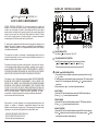
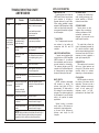
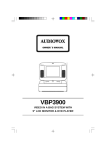
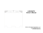
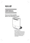
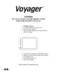
OWNER'S MANUAL
FACEPLATE CONTROLS DIAGRAM
(Figure 1)
The Mobile Electronics Company
UDIOVOX
PECIALIZED
1
PPLICATIONS, L.L.C.
2
3
4
6
5
90 DAY/12 MONTH LIMITED WARRANTY
AUDIOVOX SPECIALIZED APPLICATION, LLC ( the company) warrants to the original retail
purchaser of this product that should this product or any part thereof, under normal use and
con ditions , be proven defective in material or workm anship within 90 days from the date of
original purchase, such defect(s) will be repaired or replaced ( at the company's option) without
charge for parts and repair labor. After the initial 90 day period and for a period of 12 months
from the date of original purchase , the Company will supply at no charge a replacement for
any defective part(s), but will charge for the labor to repair the product.
1
To obtain repair or replacement within the terms of this warranty, the product is to be
delivered with proof of warranty coverage (e.g.:dated bill of sale), specification of
defect(s), transportation prepaid, to an approved warranty station, or the Company
at the address shown below.
This warranty does not extend to the elimination of externally generated static or noise, to the
correction of antenna problems, to costs incurred for removal or reinstallation of the product, or to
damage to any tapes, speakers, accessories,
This warranty does not apply to any product or part thereof which , in the opinion of the company,
has been damaged through alteration, improper installation, mishandling , misuse, neglect, or
accident,THE EXTENT OF THE COMPANY'S LIABILITY UNDER THIS WARRANTY IS LIMITED TO
THE REPAIR OR REPLACEMENT PROVIDED ABOVE, AND , IN NO EVENT, SHALL THE COMPANY'S
LIABILITY EXCEED THE PURCHASE PRICE PAID BY THE PURCHASER FOR THE PRODUCT.
This warranty is in lieu of all other express warranties or liabilities. ANY IMPLIED WARRANTIES,
INCLUDING ANY IMPLIED WARRANTY OF MERCHANTABILITY , SHALL BE LIMITED TO THE
DURATION OF THIS WARRANTY . ANY ACTION FOR BREECH OF ANY WARRANTY HEREUNDER
INCLUDING ANY IMPLIED WARRANTY OF MERCHANTABILITY MUST BE BROUGHT WITHIN
A PERIOD OF 30 DAYS FROM THE DATE OF ORIGINAL PURCHASE. IN NO CASE SHALL THE
COMPANY BE LIABLE FOR ANY CONSEQUENTIAL OR INCIDENTAL DAMAGES FOR BREECH OF
THIS OR ANY OTHER WARRANTY , EXPRESS OR IMPLIED , WHATSOEVER . No person
or representative is authorized to assume for the company any liability other that expressed
herein in connection with the sale of this product.
Some states do not allow limitations on how long an implied warranty lasts or the
exclusion or limitation of incidental or consequential damages so the above
limitations or exclusions may not apply to you. This warranty gives you specific legal
rights and you may also have other rights which vary from state to state.
AUDIOVOX SPECIALIZED APPLICATIONS, LLC
23319 COOPER DR. ELKHART, IN 46514
Visit us at http://www.asaelectronics.com
8
11
9
8
10
7
12
1
PWR (POWER) BUTTON
Push button " " to turn the power ON or OFF.
2
SEL (AUDIO MODE SELECT) BUTTON
Press SEL button to change the mode in the sequence as foll ows;
VOL
BAS
TRE
BAL
FAD
3
VOLUME "
" (AUDIO LEVEL) BUTTON
i) The volume level can be adjusted at any time by pressing the audio level " "
or " " button.
ii) The volume mode is also obtained by stepping through the "SEL" button until the
function " VOL " indicator lights up and then press " " or " " button to adjust the
sound level.
iii)Press and hold the " " or " " button to adjust the sound level.
BASS CONTROL
i) Press the "SEL" button to select the bass mode until "BAS" indicator lights up.
ii) Press " " or " " button to adjust the bass effect.
TREBLE CONTROL
i) Press the "SEL" button to select the treble mode until "TRE" indicator lights up .
ii) Press " " or " " button to adjust the treble ef fect.
BALANCE CONTROL
i) Press the "SEL" button to select the balance mode until "BAL" indicator lights up.
ii)Press " " button to decrease the sound level of left sp eakers or press " " button
to decrease the sound level of right speakers.
1
FADER CONTROL
i ) Press the "SEL" button to select the fader mode until "FAD" indicator lights up.
ii)Press " " button to decrease the sound level of rear sp eakers or press " "
button to decrease the sound level of front speakers.
4
LOC/RPT BUTTON
IN RADIO MODE Press this button once in weak signal area.
IN RADIO MODE Press it once again for strong signal area.
IN CD PLAY Press "RPT" button to play one song repeatedly.
5
CD LOADING SLOT
To load a CD through this slot. Upon a disc being loaded, CD immediately starts
to play (CD mode)
6
7
(CD EJECT) BUTTON
Push button " " to eject disc.
BUTTON (FAST REVERSE)
Press to search backward.
9
BAN(BAND) BUTTON
Each press for MW(AM)/FM
BUTTON (PLAY PAUSE)
Press to start playback, press once to pause, press again to resume play from
the point at which you pause.
11
TUNING BUTTON
Rotate the knob to tune to the desired radio station.
12
Press the button to reset
NOTE:
Do not try to insert another disc when one has
been already inserted. Doing so may damage
the unit.
Handle the disc by its edge, and to keep the
disc clean, do not touch the surface.
DISC PLAY
Cleaning discs
Before playing, clean the disc with a clean,
lint-free cloth.
Wipe the disc in the direction of the arrow.
BUTTON (FAST FORWARD)
Press to search forward.
8
10
* Do not leave the front panel in any area
expose to high temperatures or direct
sunlight.
* Do not drop the front panel or otherwise
subject it to strong impact.
* Do not allow such volatile agents as
benzine, thinner, or insecticides to come
Into contact with the surface of the front
panel.
* Never try to disassemble the front panel.
Do not stick paper or tape on the disc.
Do not expose the disc to direct sunlight or
heat sources such as hot air ducts, or leave it
in a car parked in direct sunlight where there
can be a considerable rise in temperature.
Note:
Do not use solvents such as benzine, thinners,
commercially available cleaners or antistatic
spray intended for analogue discs.
Do not Insert a disc with the label surface down. Doing so
may damage the unit.
Label
surface up
2
7
APPLICATION NOTES
This note will discuss DC Power sources and how they relate to 12 volt
products .
General Specifications
Our general specification for the voltage range of operation is 10 to
16 volts DC .
WIRING DIAGRAM
(Figure 2)
4 SPEAKERS, WITH FADER
Negative (- ) ground connection
FM
Frequency range . . . . . . . . . . . . . . .88-108 MHz
(87.5-108 MHz)
Usable sensitivity. . . . . . . . . . . . . . . . . . . . . . . . .3 V
I.F. Frequency . . . . . . . . . . . . . . . . . . . . . . 10.7 MHz
(black)
Connect to the car chassis ( - ) via the black connection lead.
Note: Ground over antenna socket is not sufficient.
Voltage
The voltage of a fully charged battery ( engine not running ) is
approximately 12.5 VDC. Once a load (items being powered represent the
"load" ) is applied , the voltage will drop. How much the voltage is reduced will
depend on the following:
1. Current draw (amount of amperage) The higher the draw the
greater the voltage will drop.
2. The size and length of the conductor (wire) supplying power.
Converters
Many boats incorporate convertors as a source for 12VDC when
connected to shore power (110-120 VAC). Some converters put out a very
clean DC supply where others may have a considerable amount of AC
ripple noise under maximum load.
This AC ripple noise is filtered by the boat battery when connected
into the circuit, but when the battery is disconnected the amount of AC
ripple noise can create major problems for audio products. Noise may
result and the line fuse may fail .
( + ) 12 volts battery / permanent
/ memory (Orange)
Connect to uninterrupted positive supply, terminal (behind the
car fuse) via the connection lead.
( + ) 12 volts/ power line
(RED)
Connect the connection cable to fuse holder terminal (switched
by the ignition switch) or to uninterrupted positive supply terminal (behind the fuse).
Connection for External Amplifier (white / red) (OPTION).
Using these connections an additional amplifier may be
connected.
RCA RED (RIGHT)
RCA WHITE (LEFT)
ANTENNA
TRANSPORTATION SCREW
BLUE POWER ANT
RED B+
FUSE (ACC)
BLACK GROUND (-)
GREEN W/BLACK
WHITE
GREY
WHITE W/BLACK
Sticker
GREEN
REAR LEFT SPEAKER
GREY W/BLACK
FRONT RIGHT SPEAKER
VIOLET
6
* OPTION
REAR RIGHT SPEAKER
(Figure 2)
Please remove this shipping screw before
installation. If the screw is left in place, the
CD mechanism will not operate.
CD PLAYER
System . . . . . . . . . . . . .Compact disc audio system
Usable disc. . . . . . . . . . . . . . . . . . . . .Compact disc
Signal format. . . . . . .Sampling frequency :44.1KHz
No of quantization bits:1bit
Frequency characteristics . . . . . . . . . . . 5-20,000Hz
Signal to noise ratio. . .70dB(1KHz)(IEC-A network)
Number of channels. . . . . . . . . . . . . . . . . . .2 stereo
* OPTION
VIOLET W/BLACK
FRONT LEFT SPEAKER
Sticker
LINE - OUT (OPTION)
Output level. . . . . . 350 mV @ FM 10% THD power
Impedance . . . . . . . . . . . . . . . . . . . . . . . . .600 ohm
GENERAL
Power requirement . . . . . . . .DC 12.0V/Rated:14.4V
Negative ground
Current consumption . . . . . . . . . . . 10 A MAXIMUM
Speaker Impedance . . . . . . . . . . . . . . . . . 4 - 8 ohm
Power Output . . . . . . . . . . . . . . . . . . . . . . . . . . 80W
Dimension (SET) . . . . . . . 178(W)x50(H)x150(L)mm
Maximum allowable Mounting angle
---Front to back . . . . . . . . . . . . . . -10 - +30
---Side to Side . . . . . . . . . . . . . . -10 - +10
CONNECTIONS
UNIT
MW (AM)
Frequency range . . . . . . . . . . . . . . . .520 -1710 KHz
(531-1602 KHz)
I.F. Frequency . . . . . . . . . . . . . . . . . . . . . . . 455 Khz
NOTE:
Specification is subject to change without further
notice
After remove the shipping screws, apply
the stickers provided on the two screw holes
in order to prevent possibility for the water
drops from getting into the unit.
3
TROUBLESHOOTING CHART
AM/FM RADIOS
Symptom
No Power
Power indicated;
no audio output
or very distorted
sound
Only one channel
(right or left side)
Cause
No 12VDC
Possible Solution
Check circuit fuse at source
Check in-line fuse on power
lead
Power lead disconnected
Ground connection
disconnected
No 12VDC to memory
lead(electronically
tuned units only)
Circuit fuse at source
In-line memory lead fuse
Speaker Output
shorted
Check continuity of speaker
leads to ground
Speaker out cross
channeled
Check for proper speaker wiring
Note: Radios have a sticker on
them explaining wiring color
code.
Radio Balance
Check radio function
Speaker Disconnected
Check speaker connection at
radio and/or speaker
Speaker lead shorted
or grounded
Check speaker wiring continuity
to ground w/tester or meter
Popping in one or
both channels
Speaker wiring shorted
or positive lead
grounded
Speaker terminals
grounded or shorted
Leads from speaker cone to
terminal touching metal basket
or speaker
No AM Reception
Antenna disconnected
Connect Antenna
Antenna mast grounded Check antenna or substitute with
or shorted
antenna known to be good
Antenna center lead
broken
Check antenna or substitute with
antenna known to be good
NOTE: Antenna leads can be tested with continuity or
multi-tester. Some may have electronic component
(capacitor) built in which not allow it to be tested.
4
APPLICATION NOTES
AM/FM RECEPTION
Some boats have more than one
AM/FM radio.The best way to insure
good reception is to supply a
separate antenna for each radio.
Other options available to supply
adequate AM/FM reception to these
radios are listed below, along with
some general information in regards
to radio reception.
"Y"ADAPTORS
The "Y" adaptors used to connect
one antenna to two radios will
compromise both AM and FM
reception.
AMPLIFIED AM/FM ANTENNA
A popular second antenna that
can be used is our AB-100 amplified
AM/FM antenna . It is small and
has a retractable mast that can be
mounted vertically or horizontally.
This antenna provides good FM
reception , but the AM reception will
be compromised to some degree
because of the length of the mast.
MAST LENGTH
AM/FM antennas compromise
AM reception by design . The
optimum mast length for FM is
approximately 30 inches which is
the standard for most automotive
antennas. The optimum mast length
for AM reception is over 100 inches
which is not practical for mobile
applications.
ANTENNA CABLE
Increasing the antenna lead
cable ( adding extensions ) will
reduce sensitivity of AM with
electronic tuned radios.
GROUND PLANES
Ground planes are also
important when considering
antenna performance. Most
automotive antennas are
designed to be mounted on the
metal body of the vehicle.
The metal body reflects the
signal interference generated by
the vehicle's electrical system
while it also provides the ground for
the antenna lead shield. All this is
necessary in order to maintain a
good signal, especially AM.
FM RECEPTION
FM reception can be received
with a very limited antenna and
strong local FM stations can be
received without an antenna ,
depending on the circumstances.
CONCLUSION:
AM/FM reception is subject to
the choice of an antenna and it's
application. There can also be a
variety of methods used to supply
signal to both primary and
secondary radios , but AM
performance is the ultimate "test"
Special circuitry in electronic
tuned radios or AM trimmers in
mechanically tuned radios, make
up for some of this difference in
optimum mast length for AM
reception.
5