1
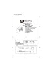
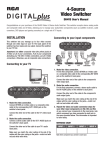
4-Source Component Video Switcher
with IR Learning
DH4CVS User's Manual
Congratulations on your purchase
switcher accepts component video,
high-tech audio/video components
consoles). And, with its special IR
toggle between inputs.
of the DH4CVS Component Video & Digital Stereo Audio Switcher. This
stereo analog audio and digital audio inputs, allowing you to manage your
(such as satellite receivers, cable converters, DVD players and gaming
learning circuit, the DH4CVS lets you use existing component remotes to
Installation
Connecting to your input components
This switcher lets you manage up to four component
video sources through one component video input on your
TV, HDTV or A/V receiver. The back panel of the switcher
has four inputs and one output. Connect the switcher to
your HDTV, TV or A/V receiver first.
Connecting to your HDTV, TV or A/V receiver
1. Make the video
connection.
Connect one end of a
component video cable to
the component video input
jacks on your TV, HDTV or A/V
receiver. Connect the other
end of the cable to the OUT Y
Pr Pb jacks on the switcher.
Make sure you match the color coding at the end of
the cables with the color coding on the jacks—match
red with red (Pr), blue with blue (Pb) and green with
green (Y).
2. Make the audio connection.
If your TV, HDTV or A/V receiver has a digital
coaxial audio jack:
Connect one end of a digital coaxial audio cable to
the digital coaxial audio input jack on your TV, HDTV
or A/V receiver. Connect the other end of the digital
coaxial audio cable to the OUT Digital jack on the
switcher.
If your TV, HDTV or A/V receiver does not have a
digital coaxial audio jack:
Connect one end of a stereo audio cable to the audio
input jacks on your TV, HDTV or A/V receiver. Connect
the other end of the stereo audio cable to the OUT L
and R jacks on the switcher.
Make sure you match the color coding at the end of
the cables with the color coding on the jacks—match
red with red (R) and white with white (L).
IMPORTANT: Match the audio connection in this step
with the audio connections available on your input
components. For example, if your input components
have only stereo audio outputs, then use the stereo
audio connection to your TV, HDTV or A/V receiver.
1. Make the video
connection.
Connect one end of a
component video cable
to the component video
output jacks on one of
your components. Connect
the other end of the cable
to the IN1 Y Pr Pb jacks on
the switcher.
Make sure you match the color coding at the end of
the cables with the color coding on the jacks—match
red with red (Pr), blue with blue (Pb) and green with
green (Y).
2. Make the audio connection.
If your component has a digital coaxial audio
jack:
Connect one end of a digital coaxial audio cable to
the digital coaxial audio output jack on the component. Connect the other end of the digital coaxial
audio cable to the IN1 Digital jack on the switcher.
If your component does not have a digital
coaxial audio jack:
Connect one end of a stereo audio cable to the audio
output jacks on the component. Connect the other
end of the stereo audio cable to the IN1 L and R
jacks on the switcher.
Make sure you match the color coding at the end of
the cables with the color coding on the jacks—match
red with red (R) and white with white (L).
IMPORTANT: Match the audio connection in this step
with the audio connection available on your TV, HDTV
or A/V receiver. For example, if your TV, HDTV or A/V
receiver has only stereo audio inputs, then use the
stereo audio connection to your input component.
3. Repeat the video and audio connection steps
for your other input components on IN2, IN3 and
IN4.
As you connect your components to the input jacks,
note which component you have connected to each
jack in the space provided below. This information
is important to have handy and is necessary when
programming remotes to operate the switcher
(See Learning Function).
Reference Chart
INPUT 1
INPUT 2
INPUT 3
INPUT 4
Note which component you connect to each input to help when
programming the Remote Control Learning Circuit.
Connecting the switcher to a power source
Connect the supplied power adapter to the
DC 9V jack on the back of the switcher. Plug
the other end of the power adapter into a
wall outlet or surge protector.
An input indicator light on the front of the
switcher turns on.
Important: This power unit is intended to be
correctly oriented in a vertical or floor mount
position.
Press the button on the front of the switcher that
corresponds to that component’s connections.
For example, if your DVD is connected to
INPUT 1, press INPUT 1 on the front of the switcher.
If your connections are correct, you should see
and hear the video and audio from INPUT 1
(the DVD).
IR LEARNING FUNCTION
This switcher is equipped with an IR Learning circuit,
allowing it to respond to the on/off commands from
your component remote(s) so that you can use them to
toggle through inputs. Once you've set up the Learning
function for a component, the switcher automatically
selects the correct input when you turn that component
on.
Note:Make sure to you know which component is connected to each input jack before you start setting
up the learning function.
Setting up the Learning function.
1. Press the LEARN key on the front panel of the
switcher for 4 seconds. The LEARN LED will flash. The
switcher is now in learning mode.
2. The CH1 LED indicator light will begin to flash. As it is
flashing, aim the component remote that you wish to
program to INPUT 1 and press any device key (DVD,
Satellite etc.). The CH1 LED will stop flashing and the
CH2 LED will begin flashing.
You must set the learning function within 8 seconds of
the LED beginning to flash. Otherwise, you will need to
begin from step 1 again.
The Learn function is set for INPUT 1. Your remote now
switches to the appropriate source. Repeat this procedure for each additional remote you wish to program for
components connected to the other 3 inputs.
Note: To cancel the learning setup process, press the
LEARN key.
Note:Universal remotes can also be programmed in the
same manner to operate the switcher. Make sure
you have the remote in the operational mode that
corresponds to the component plugged into that
input on the back of the switcher by pressing the
device button (e.g. DVD for DVD input) before you
start.
12 Month Limited Warranty
Audiovox Electronics Corporation (the “Company”) warrants to the original
retail purchaser of this product that should this product or any part thereof,
under normal use and conditions, be proven defective in material or workmanship within 12 months from the date of original purchase, such defect(s)
will be repaired or replaced (at the Company’s option) without charge for
parts and repair labor. To obtain repair or replacement within the terms of
this Warranty, the product along with any accessories included in the original
packaging is to be delivered with proof of warranty coverage (e.g. dated bill
of sale), specification of defect(s), transportation prepaid, to the Company at
the address shown below. Do not return this product to the Retailer.
This Warranty is not transferable and does not cover product purchased,
serviced or used outside the United States or Canada. The Warranty does
not extend to the elimination of externally generated static or noise. This
Warranty does not apply to costs incurred for installation, removal or reinstallation of the product, or, if in the Company’s opinion, the product has been
damaged through acts of nature, alteration, improper installation, mishandling, misuse, neglect, accident, or the simultaneous use of different battery
types (e.g. alkaline, standard or rechargeable). This Warranty does not cover
damage caused by an AC adapter not provided with the product.
THE EXTENT OF THE COMPANY’S LIABILITY UNDER THIS WARRANTY IS
LIMITED TO THE REPAIR OR REPLACEMENT PROVIDED ABOVE AND, IN NO
EVENT, SHALL THE COMPANY’S LIABILITY EXCEED THE PURCHASE PRICE
PAID BY PURCHASER FOR THE PRODUCT.
This Warranty is in lieu of all other express warranties or liabilities.
ANY IMPLIED WARRANTIES, INCLUDING ANY IMPLIED WARRANTY OF
MERCHANTABILITY OR FITNESS FOR A PARTICULAR PURPOSE, SHALL BE
LIMITED TO DURATION OF THIS WARRANTY. ANY ACTION FOR BREACH
OF ANY WARRANTY HEREUNDER, INCLUDING ANY IMPLIED WARRANTY,
MUST BE BROUGHT WITHIN A PERIOD OF 24 MONTHS FROM THE DATE OF
ORIGINAL PURCHASE. IN NO CASE SHALL THE COMPANY BE LIABLE FOR
ANY CONSEQUENTIAL OR INCIDENTAL DAMAGES WHATSOEVER. No person
or representative is authorized to assume for the Company any liability other
than expressed herein in connection with the sale of this product.
Some states/provinces do not allow limitations on how long an implied
warranty lasts or the exclusion or limitation of incidental or consequential
damage so the above limitations or exclusions may not apply to you. This
Warranty gives you specific legal rights and you may also have other rights
which vary from state/province to state/province.
U.S.A.: Audiovox Electronics Corporation, 150 Marcus Blvd., Hauppauge,
New York 11788
CANADA: Audiovox Return Center, c/o Genco, 6685 Kennedy Road, Unit 3,
Door 16, Mississauga, Ontario L5T 3A5
FCC Declaration of Conformity
This device complies with part 15 of the FCC Rules. Operation is subject
to the following two conditions: (1) This device may not cause harmful
interference, and (2) this device must accept any interference received,
including interference that may cause undesired operation.
Trade Name: Audiovox
Model(s): DH4CVS
Equipment Classification: Class B Digital Device
Responsible Party: Audiovox Accessories Corporation
111 Congressional Blvd., Suite 350
Carmel, IN 46032
Customer Service: www.rca.com
This equipment has been tested and found to comply with the limits for a
Class B digital device, pursuant to Part 15 of the FCC Rules. These limits
are designed to provide reasonable protection against harmful interference in a residential installation. This equipment generates, uses, and can
radiate radio frequency energy and, if not installed and used in accordance
with the instructions, may cause harmful interference to radio communications. However, there is no guarantee that interference will not occur in a
particular installation. If this equipment does cause harmful interference
to radio or television reception, which can be determined by turning the
equipment off and on, the user is encouraged to try to correct the interference by one or more of the following measures:
• Reorient or relocate the receiving antenna.
• Increase the separation between the equipment and receiver.
• Connect the equipment into an outlet on a circuit different from that to
which the receiver is connected.
• Consult the dealer or an experienced radio/TV technician for help.
Changes or modifications not expressly approved by the party responsible
for compliance could void your authority to operate the equipment.
©2007 Audiovox Accessories Corporation
111 Congressional Blvd., Suite 350
Carmel, IN 46032
DH4CVS US IB 00
This Class B digital apparatus complies with Canadian ICES-003.
Conmutador de video de
componente de 4 fuentes con función de Aprendizaje IR
Manual del Usuario del Modelo DH4CVS
Felicidades por su adquisición del Conmutador de video de componente y audio estereofónico digital DH4CVS. Este
conmutador admite entradas de video de componente, audio analógico estereofónico y audio digital estereofónico,
permitiéndole así manejar sus componentes de audio y video de alta tecnología (tales como receptores de satélite,
convertidores de cable, lectores de DVD y consolas de juego). Y, con su especial circuito de aprendizaje IR, el modelo
DH4CVS le permite utilizar los controles remotos existentes de sus componentes para alternar entre las entradas.
INSTALACIÓN
Cómo conectar a sus componentes de entrada
Este conmutador le permite manejar hasta cuatro fuentes
de video de componente a través de una entrada de video
de componente en su TV, HDTV o receptor de A/V. El panel
posterior del conmutador incluye cuatro entradas y una
salida. Conecte el conmutador primero a su HDTV, TV o
receptor de A/V.
Cómo conectar su HDTV, TV o receptor de A/V
1. Lleve a cabo la conexión
de video.
Acople un extremo de un cable
de video de componente a los
conectores de entrada de video
en su TV, HDTV o receptor de
A/V. Acople el otro extremo del
cable a los conectores de salida
OUT Y Pr Pb del conmutador.
Asegúrese de hacer corresponder las codificaciones por
colores en el extremo de los cables con las codificaciones
por colores en los conectores – haga corresponder el rojo
con el rojo (Pr), azul con azul (Pb) y verde con verde (Y).
2. Lleve a cabo la conexión de audio.
Si su TV, HDTV o receptor de A/V incluye un
conector de audio coaxial digital:
Acople un extremo de un cable de audio coaxial digital
al conector de entrada de audio coaxial en su TV, HDTV
o receptor de A/V. Acople el otro extremo del cable de
audio coaxial digital al conector de salida OUT Digital
del conmutador.
Si su TV, HDTV o receptor de A/V no incluye un
conector de audio coaxial digital:
Acople un extremo de un cable de audio estereofónico
a los conectores de entrada de audio en su TV, HDTV o
receptor de A/V. Acople el otro extremo del cable de audio
estereofónico a los conectores de salida OUT L y R del
conmutador.
Asegúrese de hacer corresponder las codificaciones por
colores en el extremo de los cables con las codificaciones
por colores en los conectores – haga corresponder el rojo
con el rojo (R) y blanco con blanco (L).
IMPORTANTE: Haga corresponder la conexión de audio
en este paso con las conexiones de audio disponibles
en sus componentes de entrada. Por ejemplo, si sus
componentes de entrada sólo incluyen salidas de audio
estereofónico, entonces utilice la conexión de audio
estereofónico en su TV, HDTV o receptor de A/V.
1. Lleve a cabo la conexión
de video.
Acople un extremo de un cable
de video de componente a los
conectores de salida de video
de componente en uno de
sus componentes. Acople el
otro extremo del cable a los
conectores de entrada IN1 Y
Pr Pb del conmutador.
Asegúrese de hacer corresponder las codificaciones por
colores en el extremo de los cables con las codificaciones
por colores en los conectores – haga corresponder el rojo
con el rojo (Pr), azul con azul (Pb) y verde con verde (Y).
2. Lleve a cabo la conexión de audio.
Si su componente incluye un conector de audio
coaxial digital:
Acople un extremo de un cable de audio coaxial digital al
conector de salida de audio coaxial digital en su componente. Acople el otro extremo del cable de audio coaxial
digital al conector de entrada IN1 Digital del conmutador.
Si su componente no incluye un conector de audio
coaxial digital:
Acople un extremo de un cable de audio estereofónico
a los conectores de salida de audio en el componente.
Acople el otro extremo del cable de audio estereofónico a
los conectores de entrada IN1 L y R del conmutador.
Asegúrese de hacer corresponder las codificaciones por
colores en el extremo de los cables con las codificaciones
por colores en los conectores – haga corresponder el rojo
con el rojo (R) y blanco con blanco (L).
IMPORTANTE: Haga corresponder la conexión de audio
en este paso con las conexiones de audio disponibles
en el TV, HDTV o receptor de A/V. Por ejemplo, si su TV,
HDTV o receptor de A/V sólo incluye entradas de audio
estereofónico, entonces utilice la conexión de audio estereofónico en su componente de entrada.
3. Repita los pasos de las conexiones de video y
audio para los demás componentes de entrada
en IN2, IN3 e IN4.
Cuando acople los componentes a los conectores de
entrada, anote cuáles componentes tiene acoplados a
cada conector en el espacio provisto abajo. Es importante
tener esta información a mano porque la necesitará
para poder programar los controles remotos que harán
funcionar el conmutador.
GRÁFICO DE REFERENCIA
ENTRADA 1 ENTRADA 2 ENTRADA 3 ENTRADA 4
Observe los componentes que conecta a cada una de las
entradas para ayudarle a programar el Circuito de Aprendizaje
del Control Remoto.
Cómo conectar el conmutador a una fuente
de potencia
Acople el adaptador de potencia suministrado
al conector de 9V de CC en la parte posterior
del conmutador. Enchufe el otro extremo del
adaptador de potencia en el tomacorriente de
la pared o protector contra sobrecargas.
En la parte frontal del conmutador se iluminará
una luz indicadora de entrada.
Importante: Esta unidad de potencia ha sido
diseñada para quedar correctamente orientada
en posición vertical o montaje en el piso.
Oprima el botón en la parte frontal del conmutador que
corresponde a las conexiones de dicho componente. Por
ejemplo, si su Lector de DVD se encuentra conectado a
la entrada INPUT 1, oprima INPUT 1 en la parte frontal
del conmutador. Si sus conexiones son correctas, deberá
ver y escuchar el video y el audio a través de INPUT 1
(el Lector de DVD).
FUNCIÓN DE APRENDIZAJE IR
Este conmutador está equipado con un circuito de Aprendizaje
IR, el cual le permite responder a los comandos de encendido/apagado del control(es) remoto(s) de sus componentes,
de manera que pueda utilizarlos para alternar a través
de las entradas. Una vez haya configurado la función de
Aprendizaje para un componente, el conmutador seleccionará
automáticamente la entrada correcta cuando encienda dicho
componente.
Aviso:Asegúrese de saber cuáles componentes están acoplados a cada uno de los conectores de entrada
antes de configurar la función de aprendizaje.
Cómo configurar la función de Aprendizaje.
GARANTÍA LIMITADA DE 12 MESES
Audiovox Electronics Corporation (la “Compañía”) le garantiza a usted, el
comprador original de este producto que si, bajo condiciones y uso normales,
se encontrara que este producto o alguna pieza presenta defectos materiales
o de mano de obra dentro de los primeros 12 meses a partir de la fecha de
compra original, tales defectos serán reparados o reemplazados (a opción de
la Compañía) sin cargo alguno por las piezas y labores de reparación. Para
obtener los servicios de reparación o reemplazo dentro de los términos de esta
Garantía, el producto junto con cualquier accesorio incluido en el empaque
original se entregarán con prueba de garantía (por ejemplo, factura fechada de
venta), especificación de los defectos, transporte prepagado, a la Compañía a la
dirección indicada abajo. No devuelva este producto al Distribuidor.
Esta Garantía no es transferible y no cubre un producto adquirido, mantenido
o utilizado fuera de los Estados Unidos o Canadá. Esta garantía no incluye
la eliminación de estática o ruido generados externamente. Esta garantía no
incluye los costos incurridos en la instalación, remoción o reinstalación de este
producto, o, si es opinión de la Compañía, que este producto ha sufrido daños
debido a causas de fuerza mayor, alteraciones, instalación inadecuada, abuso,
uso indebido, negligencia, accidente, o el uso simultáneo de diferentes tipos de
baterías (por ejemplo, alcalinas, típicas o recargables). Esta Garantía no incluye
daños ocasionados por un adaptador de CA que no haya sido suministrado
con el producto.
EL ALCANCE DE LA RESPONSABILIDAD DE LA COMPAÑÍA BAJO ESTA GARANTÍA
ESTÁ LIMITADO A LA REPARACIÓN O EL REEMPLAZO PROVISTO ARRIBA Y, EN
NINGÚN CASO, DEBERÁ LA RESPONSABILIDAD DE LA COMPAÑÍA EXCEDER EL
PRECIO DE COMPRA PAGADO POR EL COMPRADOR DE ESTE PRODUCTO.
Esta Garantía reemplaza cualesquiera otras responsabilidades o garantías
expresas. CUALESQUIERA GARANTÍAS IMPLÍCITAS, INCLUYENDO CUALQUIER
GARANTÍA IMPLÍCITA DE COMERCIABILIDAD O ADAPTABILIDAD PARA UN
PROPÓSITO EN PARTICULAR ESTARÁN LIMITADAS A LA DURACIÓN DE ESTA
GARANTÍA. CUALQUIER ACCIÓN PARA EL INCUMPLIMIENTO DE CUALQUIER
GARANTÍA EN EL PRESENTE, INCLUYENDO CUALQUIER GARANTÍA IMPLÍCITA,
DEBERÁ PRESENTARSE DENTRO DE UN PERÍODO DE 24 MESES A PARTIR
DE LA FECHA DE COMPRA ORIGINAL. EN NINGÚN CASO LA COMPAÑÍA
SERÁ RESPONSABLE POR DAÑOS EMERGENTES O INCIDENTALES. Ninguna
persona ni representante está autorizado a asumir, a nombre de la Compañía,
ninguna responsabilidad salvo la expresada aquí en conexión con la venta de
este producto.
Algunos estados/provincias no permiten limitaciones sobre la duración de
una garantía implícita o la exclusión o la limitación de daños incidentales o
emergentes, de modo que es posible que las limitaciones o exclusiones anteriores no se apliquen en su caso. Esta Garantía le confiere derechos legales específicos; según el estado/provincia, puede disfrutar además de otros derechos.
1. Oprima la tecla LEARN en el panel frontal del conmutador
durante 4 segundos. La luz indicadora LED “LEARN” parpadeará. El conmutador se encuentra ahora en el modo
de aprendizaje.
EE.UU.: Audiovox Electronics Corporation, 150 Marcus Blvd., Hauppauge,
New York 11788
2. La luz indicadora LED “CH1” comenzará a parpadear.
Mientras parpadea, apunte el control remoto del componente que desea programar a INPUT 1 y oprima cualquier
tecla de dispositivo (DVD, Satélite, etc.). La luz indicadora “CH1” dejará de parpadear y la luz indicadora LED
“CH2” comenzará a parpadear.
DECLARACIÓN DE CONFORMIDAD CON LA FCC
Marca comercial: Audiovox
Deberá configurar la función de aprendizaje en un espacio de 8 segundos luego de que la luz indicadora LED
comience a parpadear. De lo contrario, necesitará iniciar
el procedimiento a partir del paso 1.
La función de Aprendizaje está configurada en INPUT 1. Su
control remoto ahora cambia a la fuente correcta. Repita
este procedimiento para cada control remoto adicional que
desee programar para los componentes conectados a las
otras 3 entradas.
Aviso:Para cancelar el proceso de configuración de la
función de Aprendizaje, oprima la tecla LEARN.
Aviso:Los controles remotos universales pueden programarse de la misma manera para hacer funcionar el
conmutador. Deberá asegurarse de tener el control
remoto en el modo operativo que corresponde con el
componente enchufado a dicha entrada en la parte
posterior del conmutador oprimiendo el botón del
dispositivo (por ejemplo, DVD para entrada DVD).
©2007 Audiovox Accessories Corporation
111 Congressional Blvd., Suite 350
Carmel, IN 46032
DH4CVS US IB 00
CANADÁ: Audiovox Return Center, c/o Genco, 6685 Kennedy Road, Unit 3,
Door 16, Mississauga, Ontario L5T 3A5
Este dispositivo cumple con la Parte 15 de las Normas de la FCC. Su funcionamiento está sujeto a las siguientes dos condiciones: (1) Este dispositivo
no debe causar interferencia dañina y (2) Este dispositivo debe aceptar toda
interferencia recibida, incluida aquélla que puede causar un funcionamiento
no deseado.
Modelo(s): DH4CVS
Clasificación de equipo: Dispositivo digital Clase B
Entidad responsable: A udiovox Accessories Corporation
111 Congressional Blvd., Suite 350
Carmel, IN 46032
Servicio al cliente: www.rca.com
Este equipo ha sido probado y se consideró que cumple con los límites de los
aparatos de Clase B, de acuerdo con las especificaciones de la Sección 15 de
las Normas de la FCC. El objetivo de estos límites es ofrecer protección razonable contra interferencias perjudiciales en una instalación residencial. Este
equipo genera, utiliza y puede irradiar energía de radiofrecuencia y, si no se
instala y se usa de acuerdo con las instrucciones, puede causar interferencia
perjudicial para las comunicaciones de radio. Sin embargo, no hay garantía
de que no ocurrirá interferencia en una instalación en particular. Si su equipo
causa interferencia nociva en la recepción de radio o televisión, que puede
averiguar apagando y encendiendo el equipo, intente corregirla mediante
alguna o varias de las siguientes maneras:
• Vuelva a orientar o cambie de lugar la antena receptora.
• Aumente la separación entre el equipo y el receptor.
• Conecte este equipo a una toma en un circuito diferente al que esté
conectado el receptor.
• Consulte al distribuidor o a un técnico experimentado de radio y televisión
para solicitar asistencia.
Los cambios o modificaciones no aprobados expresamente por la parte
responsable para el cumplimiento podrían anular la autoridad del usuario
para utilizar este producto.
Este aparato digital Clase B cumple con la normativa canadiense
ICES-003.