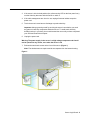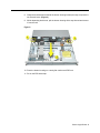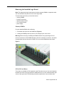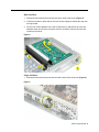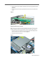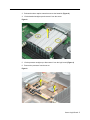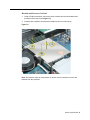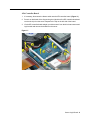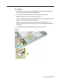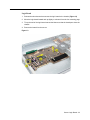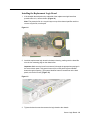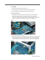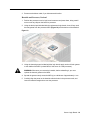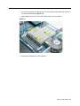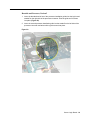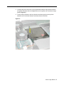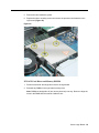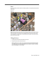
1
Xserve Logic Board Replacement Instructions Follow the instructions in this sheet carefully. Failure to follow these instructions could damage your equipment and void its warranty. Note: Online instructions covering customer-installable parts are available at http://www.info.apple.com/installparts/. Tools Required The only tool required for this procedure is a Phillips screwdriver. Opening the Server The server slides open from the front of the rack. The top cover remains in place in the rack while the bottom housing (containing all internal components) should be placed on a sturdy, flat surface. 1. Alert users that the server will be unavailable for a period of time. 2. Shut down the server. Warning: To avoid damaging internal components or causing injury, always shut down the server before opening it. After you shut down the server, internal components can be very hot. Let the server cool down before continuing. 073-0665 Rev. D 3. If the server is in the locked position (the yellow security LED on the front panel is on), use the Allen key that came with the server to unlock it. 4. If the cable management arm is not in use, unplug all external cables except the power cord. 5. Touch the server’s metal case to discharge any static electricity. Important: Always ground yourself by touching the server’s case before you touch any parts or install any components inside the server. To avoid static electricity building back up in your body, do not walk around the room until you have completed your work and closed the computer. 6. Unplug the power cord. Warning: The power supply in the server is a high-voltage component and should not be opened for any reason, even when the server is off. 7. Release the two thumb screws at the front of the server. (Figure 1) Note: The thumbscrews are captive and do not separate from the bottom housing. Figure 1 Xserve Logic Board - 2 8. Grasp the thumbscrews and slide the bottom housing forward part way to expose the two chassis levers. (Figure 2) 9. While depressing both levers, pull the bottom housing all the way forward and remove it from the rack. Figure 2 10. Place the bottom housing on a sturdy, flat surface and ESD mat. 11. Put on the ESD wrist strap. Xserve Logic Board - 3 Removing the Installed Logic Board Note: The replacement logic board does not include memory DIMMs or expansion cards. You must transfer these parts from the current logic board. To remove the logic board, you must first remove: • memory DIMMs • PCI/AGP card risers • heatsink and processor • ATA controller board • power supply Memory DIMMs For each installed DIMM, do the following: 1. Push down the ejectors on the DIMM slot. (Figure 3) 2. Holding the DIMM by both top corners, lift it straight up out of the server. Warning: When removing or installing the DIMM, handle it only by the edges. Do not touch its connectors. Lift the DIMM straight up from the connector to remove it, and insert it straight down into the connector to install it. Do not rock the DIMM from side to side. Figure 3 PCI/AGP Card Risers Three slots are available for PCI expansion cards. Two slots are on a riser card located at the back left corner of the logic board; an additional slot is on a riser card at the back right corner of the logic board. The following instructions explain how to remove both risers. Xserve Logic Board - 4 Dual-Slot Riser 1. Release the thumb screw that secures the riser’s cards to the server. (Figure 4) 2. If there are latches on either side of the riser, lift them slightly to release the riser from the logic board. 3. Pull the riser a short distance to the side to disconnect it, and then tilt the riser and attached cards up so that the card ports clear the enclosure. Remove the riser and cards from the server. Figure 4 Single-Slot Riser 1. Release the thumb screw that secures the card to the back of the server. (Figure 5) Figure 5 Xserve Logic Board - 5 2. Pull the clip on the riser forward to release the riser from the logic board connector. (Figure 6) 3. Disconnect the riser from the logic board and remove the riser and card from the server. Figure 6 Heatsink and Processor, Version 1 Note: There are two versions of the Xserve heatsink and processor. The first version includes a plastic duct that covers the heatsink. If there is no duct, skip to Version 2. 1. Release the latch on the heatsink duct from its slot, slide the duct away from the blower, and lift the end of the duct as shown. (Figure 7) 2. Remove the duct from the server. Figure 7 Xserve Logic Board - 6 3. Release the three captive screws that secure the heatsink. (Figure 8) 4. Lift the heatsink straight up and remove it from the server. Figure 8 5. Lift the processor straight up to disconnect it from the logic board. (Figure 9) 6. Remove the processor from the server. Figure 9 Xserve Logic Board - 7 Heatsink and Processor, Version 2 1. Using a Phillips screwdriver, remove the three screws that mount the heatsink and processor to the logic board. (Figure 10) 2. Carefully lift the heatsink and processor straight up and out of the server. Figure 10 Note: The heatsink is part of the processor in Version 2; do not attempt to remove the heatsink from the processor. Xserve Logic Board - 8 ATA Controller Board 1. If necessary, disconnect the blower cable near the ATA controller board. (Figure 11) 2. Press in on both ends of the clip securing the right side of the ATA controller board and remove the clip from the server. Repeat for the clip on the left side of the board. 3. Lift the ATA controller board straight up to disconnect it from the drive interconnect and logic boards and remove the board from the server. Figure 11 Xserve Logic Board - 9 Power Supply 1. Release the locking latch on the power supply cable connector and disconnect the cable from the drive interconnect board. (Figure 12) 2. Release the thumbscrew that secures the power supply to the chassis. Note: The thumbscrew is captive; you cannot remove it. 3. Grasp the metal flange of the power supply’s connector (on the left side) and lift up to disconnect the power supply from the logic board. Note: You may need to loosen the left side of the power supply and then lift at another point near the front to disengage it. Do not lift the small lip that contains the thumbscrew. 4. Holding the power supply in both hands, remove it from the server. Figure 12 Xserve Logic Board - 10 Logic Board 1. Release the thumb screw that secures the logic board to the chassis. (Figure 13) 2. Move the logic board forward and up slightly to release it from the four mounting pegs. 3. Tilt up the end of the logic board nearest the blowers so that the board ports clear the chassis. 4. Remove the board from the server. Figure 13 Xserve Logic Board - 11 Installing the Replacement Logic Board 1. If the heatsink thermal pad on the underside of the replacement logic board has protective film on it, remove the film. (Figure 14) Note: The protective film is a very thin layer on top of the thermal pad. Be careful to remove only the film, not the pad. Figure 14 2. Install the replacement logic board in the bottom housing, making sure the board fits over the four mounting pegs on the chassis floor. Important: Make sure the board’s connectors fit through the appropriate openings in the server’s back panel. Take special care to fit the clear plastic system identifier button through its opening. (The system identifier button is located low on the back panel, to the left of center.) (Figure 15) Figure 15 3. Tighten the thumb screw that secures the logic board to the chassis. Xserve Logic Board - 12 Power Supply 1. Reconnect the power supply to the logic board. 2. Tighten the thumb screw that secures the power supply to the chassis. 3. Reconnect the power supply cable to the drive interconnect board. ATA Controller Board 1. Reconnect the ATA controller board to the drive interconnect and logic boards. Note: When replacing the ATA controller board, align it over the two pairs of connectors on the drive interconnect and logic boards, making sure the “MLB” arrow printed on it points toward the logic board, and press down. (Figure 16) Figure 16 2. Reinstall the two ATA controller clips. Note: When replacing the ATA controller board clips, orient them so that the long end of each clip points away from the middle of the server. Place the inside edge of the clip into the small notch and then snap down the outer edge of the clip. (Figure 17) Figure 17 Xserve Logic Board - 13 3. Reconnect the blower cable, if you disconnected it earlier. Heatsink and Processor, Version 1 1. Position the processor over its logic board connector and press down, being careful not to touch any chips on the board or processor. 2. Using the alcohol pad included with the replacement logic board, clean off any used thermal grease from the processor MPU (Figure 18) and the bottom of the heatsink. Figure 18 3. Using the thermal grease included with the logic board, apply one dot of fresh grease to the middle of the MPU (or both MPUs if the server is a dual processor). ≠ WARNING: Whenever you remove the heatsink, before reinstalling it, you must replace the thermal grease on the MPU. 4. Spread the grease evenly across the MPU(s) to a thickness of approximately 1 mm. 5. Carefully align the posts on the heatsink with the holes in the processor card, and lower the heatsink straight down onto the processor. Xserve Logic Board - 14 6. To ensure the grease spreads evenly over the processor, lightly tighten the screws in the order indicated below. (FIgure 19) 7. Again tighten the screws in the order indicated to secure the heatsink. Figure 19 8. Replace the heatsink duct on the heatsink. Xserve Logic Board - 15 Heatsink and Processor, Version 2 1. Insert the threaded end of one of the processor installation guides into the logic board standoff on the right side of the processor connector. Twist the guide until it screws into place. (Figure 20) 2. Insert the second processor installation guide into the standoff on the left side of the processor connector and twist until the guide screws into place. Figure 20 Xserve Logic Board - 16 3. Carefully align the screw holes on the replacement heatsink and processor with the two guides, and lower the unit straight down over the guides until it touches the logic board. (Figure 21) 4. To secure the processor to the logic board, press down gently on the top of the heatsink cover in the area directly over the processor's connector. Figure 21 Xserve Logic Board - 17 5. Remove the two installation guides. 6. Replace the three mounting screws and secure the processor and heatsink to the logic board. (Figure 22) Figure 22 PCI/AGP Card Risers and Memory DIMMs 1. Reconnect the dual- and single-slot risers to the logic board. 2. Reinstall any DIMMs in the logic board memory slots. Note: DIMMs are designed to fit into memory slots only one way. Be sure to align the notch in the DIMM with the small rib inside the slot. Xserve Logic Board - 18 Battery Remove the battery insulator tab from the battery holder on the replacement logic board. (Figure 23) Figure 23 Note: Replacing the logic board in the server changes its Ethernet ID number. The new number is printed on an Ethernet ID label packaged with the replacement logic board. After installing the new logic board, cover the Ethernet ID number on the server’s back panel with the new ID label. Closing the Server 1. Carefully slide the bottom housing back into the rack. 2. Tighten the front thumb screws to secure it. Warning: Never turn on the server unless all of its internal and external parts are in place and it is closed. Operating the server when it is open or missing parts can damage it or cause injury. Xserve Logic Board - 19 Apple Computer, Inc. © 2003 Apple Computer, Inc. All rights reserved. This document is protected under U.S. Copyright Law and International Treaties, and no part of this document may be reproduced in any form without written permission from Apple. Apple is not responsible for typographical, printing, or inadvertent errors. Apple Computer, Inc. 1 Infinite Loop Cupertino, CA 95014-2084 USA + 1 408 996 1010 http://www.apple.com Apple, the Apple logo, Mac, Macintosh, and the Mac logo are trademarks of Apple Computer, Inc., registered in the U.S. and other countries. Power Mac is a trademark of Apple Computer, Inc. Xserve Logic Board - 20