1
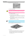
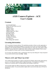
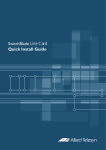
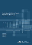
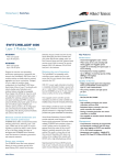
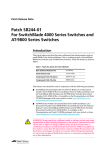
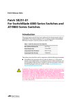
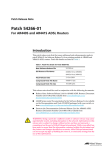
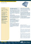
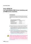
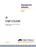
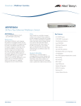
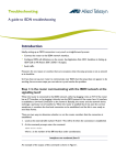
SWITCHBLADE SWITCH CONTROLLER
QUICK INSTALL GUIDE
SwitchBlade Switch Controller Quick Install Guide
Document Number C613-04031-01 REV B.
Copyright © 2003, 2002 Allied Telesyn International, Corp. 19800 North Creek Parkway,
Suite 200, Bothell, WA 98011, USA.
All rights reserved. No part of this publication may be reproduced without prior written
permission from Allied Telesyn.
Allied Telesyn International, Corp. reserves the right to make changes in specifications
and other information contained in this document without prior written notice. The
information provided herein is subject to change without notice. In no event shall Allied
Telesyn be liable for any incidental, special, indirect, or consequential damages
whatsoever, including but not limited to lost profits, arising out of or related to this
manual or the information contained herein, even if Allied Telesyn has been advised of,
known, or should have known, the possibility of such damages.
All trademarks are the property of their respective owners
Quick Install Guide
3
Documentation Roadmap
SwitchBlade
Safety and Statutory Information Booklet
Hardware Reference
Software Reference
General Customer Support
Chassis & Fan Tray Quick Install Guide
Visit www.alliedtelesyn.co.nz for
the latest documentation, FAQs,
and support information.
Power Supply Unit Quick Install Guide
Switch Controller Quick Install Guide
Line Card Quick Install Guide
Bandwidth Expander Quick Install Guide
CAM Quick Install Guide
Printed
Acrobat PDF
Website
Models Covered By This Guide
This Quick Install Guide includes information on installing the following card:
■
AT-SB4211 Switch Controller
Information on installing line cards can be found in the SwitchBlade Line Card
Quick Install Guide.
Quick Install Guide updates can be downloaded from
www.alliedtelesyn.co.nz/support/switchblade/.
Package Contents
The following items are included with each switch controller. Contact your
sales representative if any items are damaged or missing.
C613-04031-01 REV B
■
One SwitchBlade Switch Controller.
■
One CPU memory pack, with two 128 MByte Dual In-line Memory
Modules (DIMMs).
■
One SwitchBlade Documentation and Tools CD-ROM (which includes the
complete SwitchBlade Documentation Set and utilities).
■
One SwitchBlade Switch Controller Quick Install Guide.
■
One Safety and Statutory Information booklet.
■
One warranty card.
4
SwitchBlade Switch Controller
Related items that can be purchased separately:
■
CPU memory pack, 256 MByte DRAM (2 x 128 MByte DIMMs).
■
SwitchCAM (Content Addressable Memory) for enhanced L2/L3
forwarding-database table size, 128 k-entry modules.
■
Blank faceplates for switch controller and line card bays (AT-SB4193).
Installing A Switch Controller
Switch controllers can be hot swapped. There is no need to power down the switch when
installing or removing switch controllers. The switch will continue to operate as long as
at least one functional switch controller remains in place, although a brief pause in
switching and routing may occur.
Follow these steps to install a switch controller:
1.
Read the safety information
For safety information, see the Safety and Statutory Information booklet. A
copy of this booklet is supplied with each switch controller. A PDF version
can be found on the CD-ROM that ships with every switch controller and
every chassis.
2.
Gather the tools and equipment you will need
To loosen or secure the switch controller’s mounting screws you will need
a Phillips #2 screwdriver.
3.
Choose a bay for the switch controller
The first switch controller to be installed in a chassis should be installed in
switch controller bay A.
Do not attempt to install a switch controller in a line card bay (bays 1 to 8 on
the SwitchBlade 8, and bays 1 to 4 on the SwitchBlade 4). Attempting to install
a switch controller in a line card bay is likely to damage the switch controller
and chassis.
4.
Prepare the switch controller
In an antistatic environment, remove the switch controller from its packing
material. Be sure to observe ESD precautions.
Do not attempt to install a switch controller without observing correct
antistatic procedures. Failure to do so may damage the switch controller and
chassis. If you are unsure what the correct procedures are, contact your
authorised Allied Telesyn distributor or reseller.
An ESD socket is provided on the front panel of the SwitchBlade chassis. The socket is
designed to be used in conjunction with an ESD wrist strap (see Figure 1 on page -5).
C613-04031-01 REV B
Quick Install Guide
5
Figure 1: ESD socket on the SwitchBlade 8 chassis.
ESD socket
5.
Install the CPU memory pack
Only Allied Telesyn supplied DIMMS have been tested and approved for use
with SwitchBlade switch controllers. Using DIMM that has not been approved
may cause unreliable operation and will invalidate the switch controller’s
warranty.
In an antistatic environment:
a) Lay the switch controller on a flat surface
b) Unpack the memory pack’s two DIMMs
c)
Holding a DIMM at an angle of about 30 degrees from horizontal, align
the notches on its connector strip with the notches on a DIMM slot (see
Figure 2 on page -5)
d) Insert the DIMM into the DIMM slot, sliding it along the two guides
until the retaining latches click into place. The latches should hold the
DIMM firmly in place
e) Repeat the process for the second DIMM
For the switch to function, both DIMMs must be installed (giving 256 MBytes of
DRAM per switch controller).
Figure 2: Installing DIMM on the AT-SB4211 Switch Controller.
DIMM
DIMM slot
6.
Install CAM
If you purchased Content Addressable Memory (CAM) modules, install
them now by following the instructions in the CAM Quick Install Guide.
The CAM Quick Install Guide can be found on the SwitchBlade
Documentation and Tools CD-ROM, or can be downloaded from
www.alliedtelesyn.co.nz.
C613-04031-01 REV B
6
SwitchBlade Switch Controller
7.
Prepare the switch controller bay
Remove the switch controller bay faceplate or existing switch controller
To remove a bay’s faceplate:
Loosen the faceplate’s two Phillips mounting screws until they disengage
from the chassis, then remove the faceplate.
Keep the faceplate for future use. If you should remove a switch controller, replace the
faceplate to prevent dust and debris from entering the chassis and to maintain proper
airflow.
The switch may overheat or be damaged by dust and debris if bays are left
uncovered.
To remove an existing switch controller:
Loosen the switch controller’s two Phillips mounting screws until they
disengage from the chassis.
Move the switch controller’s ejector levers to the unlocked position (see
Figure 3 on page -6).
Slide the switch controller out of the chassis, keeping the controller in a
straight alignment so it doesn’t jam.
Figure 3: Ejector levers.
8.
Insert the new switch controller
Make sure the switch controller’s metal back-panel is aligned with the card
guides (see Figure 4 on page -7).
Switch Controllers are mounted vertically in the SwitchBlade 8 (AT-SB4108) chassis
and horizontally in the SwitchBlade 4 (AT-SB4104) chassis.
With the ejector levers in the unlocked position (see Figure 3 on page -6),
carefully slide the switch controller into the chassis.
The ejectors’ locking mechanisms should align with their slots in the
chassis (see Figure 5 on page -7).
C613-04031-01 REV B
Quick Install Guide
7
When inserting a switch controller, take care to slide the back-panel along both
guides at an equal rate. If a switch controller becomes tight, it must not be
forced. Instead, gently withdraw the controller and try again, taking extra care
to keep the controller aligned with the guides. Forcing a misaligned or jammed
switch controller is likely to damage the controller or chassis.
Figure 4: Card guides on the SwitchBlade 8 chassis.
bottom controller guide
Figure 5: Ejector lever and locking slot.
Extractor lever
9.
Secure the switch controller
Move the ejector levers to the locked position (see Figure 3 on page -6) and
tighten the switch controller’s mounting screws.
10. Check the switch controller is receiving power
The switch controller’s Power LED will light green if the controller is
receiving power.
If the power LED fails to light:
For AC chassis models, ensure that:
C613-04031-01 REV B
•
The IEC power cords are plugged into the correct sockets on the
chassis’s rear panel. The sockets should correspond to PSU bays that
have PSUs installed.
•
The IEC power cords are plugged into supply circuits that are receiving
power and all switches are in the ON position.
•
The standby switch on the chassis is in the Run position
8
SwitchBlade Switch Controller
For DC chassis models, ensure that:
•
The correct DC terminal blocks on the chassis’s rear panel are wired.
The blocks should correspond to PSU bays that have PSUs installed.
•
The DC terminals are wired to the correct polarity.
•
The circuit breaker supplying the DC supply circuit is On.
•
The standby switch on the chassis is in the Run position.
Further troubleshooting information can be found in the SwitchBlade
Hardware Reference.
Configuring The Switch Controller
If this is the only switch controller installed in the chassis you will need to
configure it in order to access the switch’s advanced switching capabilities.
Switch controllers can be configured via the Command Line Interface (CLI) or
Graphical User Interface (GUI).
If a switch controller running the same software release and software licences is
already installed in the chassis, the second switch controller (the slave) will
automatically replicate the first controller’s (the master’s) configuration.
.If two switch controllers are installed, and a system reset or power cycle
occurs, the controller in Bay A will assume master status. Forcing a system
reset or power cycle while installing a new controller in Bay A will therefore
cause any configuration on a controller in Bay B to be overwritten.
To retain the configuration of a controller in Bay B, either remove the controller
from Bay B and place it in Bay A before installing a new controller, or hot swap
the new controller into Bay A.
Using the CLI to configure a switch controller:
1.
Connect a terminal or PC to RS-232 (ASYN0)
Use an RS-232 DB9 cable to connect your terminal or PC to the RS-232
Terminal Port (ASYN0) on the master switch controller. Two RS-232 DB9
cables are supplied with each chassis.
If two switch controllers are installed, and the switch has not yet been connected to a
power supply, the switch controller in Bay A will assume master controller status. In all
cases the master controller is the controller whose Master LED is lit.
2.
Set the communication parameters
Set the communication parameters on your terminal or terminal emulation
program to:
•
Baud rate: 9600
•
Data bits: 8
•
Parity: None
•
Stop bits: 1
•
Flow control: Hardware
See the SwitchBlade Hardware Reference for more information on configuring
C613-04031-01 REV B
emulation software.
Quick Install Guide
9
3.
Check the power supply
Ensure the chassis’s standby switch is in the Run position and the switch
controller is receiving power (Power LED lights green).
4.
Log in
After the switch controller has booted, the log in prompt appears. If the log
in prompt doesn’t appear, press [Enter] two or three times.
When the switch controller boots for the first time it automatically creates
an account with manager privileges. The account has the log in name
“manager” and the password is “friend”.
At the log in prompt, enter the log in name and password.
Login: manager
Password: friend
The command prompt appears and you can now use the CLI to configure
the switch controller.
Change the password as soon as possible. Leaving the manager account with
the default password is a serious security risk. Make sure you remember the
new password as there is no way to retrieve it if it is lost.
Use the following command to change the account password:
set password
5.
Load help files
To access help, enter:
set help=help-filename
where help-filename is the name of a help file stored in flash.
To see a list of files stored in flash, enter:
show file
Help files have an HLP extension.
To display a list of help topics, enter:
help
To display help on a specific topic, enter:
help topic
Alternatively, type a question mark (?) at the end of a partially completed
command to see a list of valid options.
See the SwitchBlade Software Reference for more information on configuring
the switch.
Using the GUI to configure a switch controller
The GUI can be accessed through ETH0 on the master switch controller.
ETH0 has a default IP address of 192.168.242.242 and a mask of
255.255.255.0.
If another device on your network already uses 192.168.242.242, do not connect
ETH0 to the network until you have changed the default address. The address
can be changed using ASYN0 and the CLI.
C613-04031-01 REV B
10
SwitchBlade Switch Controller
For instructions on using ASYN0 and the CLI to change ETH0’s IP address,
see the “Graphical User Interface” section in the “Operations” chapter of
the SwitchBlade Software Reference.
1.
Connect a PC to ETH0
Use a straight-through Ethernet patch cable to connect your PC to ETH0 on
the master switch controller. Two straight-through Ethernet patch cables
are supplied with each chassis.
The PC should be running Internet Explorer version 5.x, with JavaScript
enabled. A copy of Internet Explorer can be found on the Documentation
and Tools CD-ROM that is bundled with every chassis and every switch
controller.
If two switch controllers are installed, and the switch has not yet been connected to a
power supply, the switch controller in Bay A will assume master controller status. In all
cases the master controller is the controller whose Master LED is lit.
2.
Access the GUI
Assign the PC an IP address in the 192.168.242.0 subnet.
If you access the Internet through a proxy server, set your browser to
bypass the proxy for 192.168.242.242.
Point your web browser at 192.168.242.242.
3.
Log in
At the log in prompt, enter the log in name and password.
User Name: manager
Password: friend
The system status page appears and you can now use the GUI to configure
the switch controller.
To ensure configuration settings are saved correctly, use the GUI pages’ menus and
buttons to navigate, not your browser’s buttons.
As a security precaution, change the password and default IP address as soon
as possible.
To change the password, select Management > Users from the sidebar
menu. Select the Manager account and click Modify.
To change ETH0’s IP address, select Configuration > System >
Management from the sidebar menu.
4.
To access context-sensitive help
Click on the Help Button [Help] on each page.
C613-04031-01 REV B
Quick Install Guide
11
Switch Controller LEDs
The following LEDs will operate if the switch controller is receiving power.
Table 1: LEDs on the AT-SB4211 Switch Controller.
LED
State
Function
Power
Green
The switch controller is receiving power
Master
Amber
The switch controller is the master controller
Off
The switch controller is the slave controller
Red
The switch controller or management software is
malfunctioning
2 Flashes
A fan-tray fan has failed
3 Flashes
A PSU or PSU fan is malfunctioning
5 flashes
The fan tray has been removed for more than 20
seconds
6 Flashes
The switch’s internal temperature has exceeded
the alarm threshold
Slow flashing at
startup
The SDRAM (DIMM) has not been detected
Rapid flashing at
startup
The SDRAM (DIMM) is not compatible with the
switch
Green
A 100 Mbps management port link is open
Amber
A 10 Mbps management port link is open
Flashing green
100 Mbps activity is occurring through the
management port
Flashing amber
10 Mbps activity is occurring through the
management port
D/C
Green
The management port is operating at full-duplex
(Duplex/
Collision)
Amber
The management port is operating at half-duplex
Flashing
Collisions are occurring on the management port
link
Fault
L/A
(Link/Activity)
The SwitchBlade Hardware Reference has further troubleshooting information,
including information on line card and power supply unit LEDs.
C613-04031-01 REV B
12
SwitchBlade Switch Controller
Documentation And Tools CD-ROM
The Documentation and Tools CD-ROM bundled with every switch controller
and every chassis contains the complete Documentation Set for your switch
and its expansion options, as well as tools for managing the switch. This
includes:
■
The SwitchBlade Safety and Statutory Information Booklet, which provides
safety and statutory information for the SwitchBlade and its accessories.
■
The SwitchBlade Hardware Reference, which provides detailed information
on the switch and its hardware features.
■
The SwitchBlade Software Reference, which provides detailed information on
configuring the switch and its software.
■
This Quick Install Guide.
■
The SwitchBlade Line Card Quick Install Guide, which outlines the procedure
for installing line cards.
■
The SwitchBlade Power Supply Unit Quick Install Guide, which outlines the
procedure for installing AC and DC power supply units.
■
The SwitchBlade Chassis and Fan Tray Quick Install Guide, which outlines the
procedure for installing the chassis and its fan tray.
■
The SwitchBlade Bandwidth Expander Quick Install Guide, which outlines the
procedure for installing bandwidth expanders.
■
The CAM Quick Install Guide, which outlines the procedure for installing
Content Addressable Memory.
■
AT-TFTP Server for Windows, for downloading software releases.
■
Adobe Acrobat Reader, for viewing online documentation.
■
Microsoft Internet Explorer.
C613-04031-01 REV B