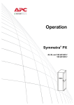
1
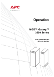
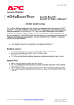
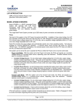
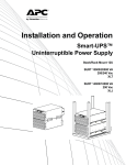
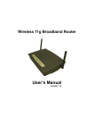
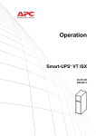
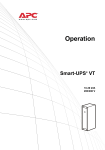
Operation and
Maintenance
Symmetra® PX
10-40 kW
208 V
Contents
IMPORTANT SAFETY INSTRUCTIONS . . . . . . . . . . . . . . . . . . . . . 1
SAVE THESE INSTRUCTIONS . . . . . . . . . . . . . . . . . . . . . . . . . . . 1
Symbols used in this guide . . . . . . . . . . . . . . . . . . . . . . . . . . . . 1
ON, OFF & STAND-BY switch positions . . . . . . . . . . . . . . . . . . . 1
Weight symbols . . . . . . . . . . . . . . . . . . . . . . . . . . . . . . . . . . . . 2
Operation safety . . . . . . . . . . . . . . . . . . . . . . . . . . . . . . . . . . . . 2
Total Power OFF procedure . . . . . . . . . . . . . . . . . . . . . . . . . . . . 2
Overview of System Components . . . . . . . . . . . . . . . . . . . . . . . 4
Weights . . . . . . . . . . . . . . . . . . . . . . . . . . . . . . . . . . . . . . . . . . 5
Operation . . . . . . . . . . . . . . . . . . . . . . . . . . . . . . . . . . . . . . . . 6
Control functions . . . . . . . . . . . . . . . . . . . . . . . . . . . . . . . . . . . 8
Control screen . . . . . . . . . . . . . . . . . . . . . . . . . . . . . . . . . . . . . . 8
Status functions . . . . . . . . . . . . . . . . . . . . . . . . . . . . . . . . . . . . 9
Status screens . . . . . . . . . . . . . . . . . . . . . . . . . . . . . . . . . . . . . . 9
Set-up functions . . . . . . . . . . . . . . . . . . . . . . . . . . . . . . . . . . . 11
Set-up screens . . . . . . . . . . . . . . . . . . . . . . . . . . . . . . . . . . . . . 11
Accessories screen . . . . . . . . . . . . . . . . . . . . . . . . . . . . . . . . . . 12
Logging screen . . . . . . . . . . . . . . . . . . . . . . . . . . . . . . . . . . . . 13
Display screens . . . . . . . . . . . . . . . . . . . . . . . . . . . . . . . . . . . . 13
Diag screens . . . . . . . . . . . . . . . . . . . . . . . . . . . . . . . . . . . . . . 14
Help screens . . . . . . . . . . . . . . . . . . . . . . . . . . . . . . . . . . . . . . 14
Network connection/APC Web Management Card . . . . . . . . . . 14
Quick configuration . . . . . . . . . . . . . . . . . . . . . . . . . . . . . . . . 15
Maintenance Bypass Operation for Installations with
Optional MBP . . . . . . . . . . . . . . . . . . . . . . . . . . . . . . . . . . . . . 16
How to place the UPS in Maintenance Bypass operation . . . . . 16
How to return to On-Line Operation from
Manual Bypass operation . . . . . . . . . . . . . . . . . . . . . . . . . . . . 18
Symmetra PX 10-40 kW 208 V Operation & Maintenance Guide - 990-4104C
i
Module and Card Replacement . . . . . . . . . . . . . . . . . . . . . . . . 21
How to replace Power Modules . . . . . . . . . . . . . . . . . . . . . . . . 21
How to replace Battery Units . . . . . . . . . . . . . . . . . . . . . . . . . . 22
How to replace Cards . . . . . . . . . . . . . . . . . . . . . . . . . . . . . . . 22
How to replace Intelligence Modules . . . . . . . . . . . . . . . . . . . . 23
How to obtain replacement Modules . . . . . . . . . . . . . . . . . . . . 23
Replacement parts and numbers . . . . . . . . . . . . . . . . . . . . . . . 24
Troubleshooting . . . . . . . . . . . . . . . . . . . . . . . . . . . . . . . . . . . 25
General status . . . . . . . . . . . . . . . . . . . . . . . . . . . . . . . . . . . . . 25
General fault . . . . . . . . . . . . . . . . . . . . . . . . . . . . . . . . . . . . . . 28
Module failure . . . . . . . . . . . . . . . . . . . . . . . . . . . . . . . . . . . . . 30
Threshold alarm . . . . . . . . . . . . . . . . . . . . . . . . . . . . . . . . . . . 30
Bypass . . . . . . . . . . . . . . . . . . . . . . . . . . . . . . . . . . . . . . . . . . . 31
System Re-Start (if applicable) . . . . . . . . . . . . . . . . . . . . . . . . . 32
Secure the UPS by setting the stabilizing feet . . . . . . . . . . . . . . 32
Level the UPS (recommended) . . . . . . . . . . . . . . . . . . . . . . . . . 32
Module Installation . . . . . . . . . . . . . . . . . . . . . . . . . . . . . . . . . 33
Battery Module installation . . . . . . . . . . . . . . . . . . . . . . . . . . . 33
Power Module installation and securing . . . . . . . . . . . . . . . . . 34
Connecting communication cables . . . . . . . . . . . . . . . . . . . . . . 35
System Re-Start Procedure . . . . . . . . . . . . . . . . . . . . . . . . . . . . 36
ii
Symmetra PX 10-40 kW 208 V Operation & Maintenance Guide - 990-4104C
IMPORTANT SAFETY INSTRUCTIONS
SAVE THESE INSTRUCTIONS
This guide contains important instructions that should be followed when handling the UPS, Battery
Enclosures, and Batteries.
Symbols used in this guide
WARNING!
Risk of electric shock.
CAUTION!
Read this information.
Indicates important information.
Indicates a heavy load that should not be lifted without assistance.
Indicates that more information is available on this subject in a different section of this
manual.
Indicates that more information is available on the same subject in a different manual.
ON, OFF & STAND-BY switch positions
Indicates that a switch or current protection device is in the ON position.
Indicates that a switch or a breakeris in the OFF position for.
Indicates that a switch is in the STAND-BY position.
Symmetra PX 10-40 kW 208 V Operation & Maintenance Guide - 990-4104C
1
IMPORTANT SAFETY INSTRUCTIONS
Weight symbols
<40 lb
40 - 70 lb.
70 - 120 lb
>120 lb
Operation safety
WARNING!
- Hazardous electrically-charged parts inside the UPS are energized from the
battery supply even when the AC power is disconnected. Follow Total Power Off
procedure to completely de-energize the system.
- Remove all conductive jewelry such as chains, watches, and rings before handling
the Battery Units.
- Battery Units do not contain serviceable parts. Do not open.
- Do not dispose of Battery Units in a fire, as they may explode. Do not mutilate
Battery Units, as released electrolyte is harmful to the skin and eyes and may be
toxic.
WARNING!
After the UPS has been electrically wired, do not start it up. Start-up is
commissioned to APC-authorized personnel only.
For configurations including customer-supplied external batteries, refer to
manufacturer’s battery installation and maintenance instructions.
Total Power OFF procedure
WARNING!
Before electrical installation begins, verify that the UPS is in the Total Power Off
mode by following this procedure.
2
Symmetra PX 10-40 kW 208 V Operation & Maintenance Guide - 990-4104C
IMPORTANT SAFETY INSTRUCTIONS
BATT
ERY
UNIT
ON
OFF
OFF
Set System Enable Switch to the STAND-BY position.
Set DC Disconnect to the OFF position.
Disconnect ALL Battery Units by removing or pulling out to Red Disconnect Line
CAUTION!
To ensure solid stability, do not pull Battery Units out beyound the Red Disconnect Line
unless completely removing them from the UPS.
Set utility power to the OFF or LOCKED OUT position.
Symmetra PX 10-40 kW 208 V Operation & Maintenance Guide - 990-4104C
3
Overview of System Components
Intelligence
Modules (2)
Power
Module
Bays
PowerView Display
ESC
?
Power
Module
Battery Module Bays
System Power Supply Cards
DC Disconnect Switch
System Enable Switch
Smart Slots (2)
Battery
Unit
G
uid
e
Sy
Qm
u
Sy ickm-Se
Q m tatr
u ic m rt a T
k -Se U M
tatra TserPX
rt M G
U
se P u id e
r X
Web Management Card
Switch Gear Monitor Card
Input / Output Chassis
Display/Computer
Interface Card
System ID Card
Battery Monitor Card
Documentation Storage Tray
Bypass Static Switch Module
XR Communication Card
4
Symmetra PX 10-40 kW 208 V Operation & Maintenance Guide - 990-4104C
Overview of System Components
Weights
UPS (empty)
600 lb. (275 kg)
Power Module
60 lb. (26 kg)
Battery Module
4 x 50 lb. (4 x 23 kg)
Symmetra PX 10-40 kW 208 V Operation & Maintenance Guide - 990-4104C
5
Operation
The PowerView is the user control interface to the UPS. It is used to configure and monitor the
system, set alarm thresholds, and provide audible and visual alarms.
Four LED indicators
report the operational
status of the UPS.
Liquid crystal
display (LCD)
LOAD ON
ON BATT
BYPASS
Chrg 100%
Load 000%
120Vin 000Vout 60Hz
Runtime: 00hr 30m
Five navigation keys are used to
select and open menu items,
access information, change system
parameters, and launch contextsensitive help.
ESC
?
FAULT
6
LOAD ON LED - When green, the Symmetra PX UPS is providing power to the load
equipment.
ON BATT LED - When yellow, power is flowing from the batteries to the Power Modules.
BYPASS LED - When yellow, power to the load is being supplied through the Bypass Static
Switch.
FAULT LED - When red, a fault condition exists.
LCD - Display alarms, status data, instructional help, and configuration items.
UP and DOWN navigation keys - Selects menu items and accesses information.
ENTER key - Opens menu items and input changes to system parameters.
HELP key - Launches context-sensitive help.
ESC key - Returns to previous screen displayed.
Symmetra PX 10-40 kW 208 V Operation & Maintenance Guide - 990-4104C
Operation
Press ESC ESC until you get to the Top-Level Status Screen, which provides you with basic
system status information.
Chrg 100%
Load 000%
120Vin 000Vout 60Hz
Runtime: 0hr 0m
Top-Level Status Screen
(factory default)
Press Enter
to open the Top-Level Menu screen. This screen is the launching pad to
command, configure, and monitor the system.
Selector
Arrow
Control
Status
Setup
Accessories
Logging
Display
Diags
Help
Top-Level Menu
Press Up and Down
to navigate the selector arrow and view all sub-menu screens.
Bat Voltage: 215V
Bat Capacity 100.0%
Runtime: 01hr 30min
16 Batts, 00Bad
Capacity: 40.0kVA
Fault Tolerance: n+1
Total UPS Modules: 5
Bad UPS Modules: 00
Battery Module Status Screen
Power Module Status Screen
Scroll arrows indicate additional screens
Press Up, Down
information.
and Enter
Low Batt Dur:
2min
20sec
Shutdwn Dly:
Return Dly:
0sec
Return Bat Cap:
0%
Shutdown Menu
to move input arrow to select and enter
Low Batt Dur:
10min
Shutdwn Dly:
20sec
Return Dly:
0sec
Return Bat Cap:
0%
Shutdown Menu
Input arrows indicate changeable options
Symmetra PX 10-40 kW 208 V Operation & Maintenance Guide - 990-4104C
7
Operation
Control functions
Selector
Arrow
Control
Status
Setup
Accessories
Logging
Display
Diags
Help
Top-Level Menu
Turn load on/off:
Graceful Turn Off
Start Runtime Cal
Turn Load On
UPS LOAD IS OFF
Load Off Screen
Control Sub-Menu
Turn into/out of bypass:
UPS into Bypass
Do Self Test
Simulate Power Fail
Graceful Reboot
Control Menu
UPS IS BYPASSED
Bypassed Screen
Additional control functions:
Do Self Test
Initiate a system of self-tests and diagnostics
Simulate Power Fail
Simulate a power failure
Graceful Reboot
Turn off and start load equipment correctly
Graceful Turn Off
Shut down load equipment correctly
Start Runtime Cal
Begin runtime calibration of the UPS
Control screen
From the Control screen, you can select the following items:
Statu
8
UPS into Bypass
Place into or return from maintenance bypass operation
Do Self Test
Initiate a system of self-tests and diagnostics.
Simulate Power Fail
Simulate a power failure
Graceful Reboot
Turn off and start load equipment in an ordinary manner.
Graceful Turn Off
Shut down load equipment in an orderly manner.
Start Runtime Cal
Begin runtime calibration of the UPS.
Turn Load On/Off
Apply power to or shut down the UPS
Symmetra PX 10-40 kW 208 V Operation & Maintenance Guide - 990-4104C
Operation
Status functions
Selector
Arrow
Control
Status
Setup
Accessories
Logging
Display
Diags
Help
Top-Level Menu
Verify general module status:
Control
Status
Setup
Accessories
Logging
Display
Diags
Help
Top-Level Menu
Capacity: 40.0kVA
Fault Tolerance: n+1
Total Pwr Modules: 05
Bad Pwr Modules: 0
Sub-Sub-Sub Status Screen
Verify voltage on all phases:
Control
Status
Setup
Accessories
Logging
Display
Diags
Help
Top-Level Menu
0
1
2
3
Vin
119.6
119.4
119.6
Vbyp Vout
119.2 0.0
119.4 0.0
119.3 0.0
Status Screen
Verify battery voltage/capacity:
Control
Status
Setup
Accessories
Logging
Display
Diags
Help
Top-Level Menu
Bat Voltage: 215V
Bat Capacity: 10.0%
Self Test: None
Sub-Sub Status Screen
Allow a 24-hour battery recharging period after system start-up/battery replacement for
battery monitoring data to become fully reliable.
Status screens
The status screen display information regarding load, battery, power module voltage, and current.
Status screen 1.
Vin, Vout, Iout
The input voltage (V), output voltage (V), and output current (A) for each phase
(1-3).
Symmetra PX 10-40 kW 208 V Operation & Maintenance Guide - 990-4104C
9
Operation
Status screen 2.
%load assuming no
redundancy
Percentage of the load in relation to the total capacity of all power modules.
Status screen 3.
%load allowing for
n+ redundancy
Percentage of the load, allowing for the redundancy in your system.
Status Screen 4.
Frequencies
The input and output frequency in hertz (Hz).
Status screen 5.
Batt Voltage
Actual voltage of the DC bus (volts).
Batt Capacity
Percentage of battery capacity available.
Runtime
The available runtime for battery operation in hours and minutes.
#Batts
The number of installed battery modules.
#Bad
The number of failed battery modules.
Status screen 6.
Capacity: kVA
The system load capacity.
Fault Tolerance
The configured redundancy for your UPS (n+0, n+1, n+2...).
Total Pwr Modules
The number of power modules installed.
Bad Pwr Modules
The number of failed power modules installed.
Status screen 7.
Alarm Thresholds
Settings configured for the thresholds that trigger alarms.
Fault Tolerance n+0
The alarm threshold for reduced redundancy.
Runtime hr min
The alarm threshold for reduced runtime.
load: kVA
Alarm indication of exceeded load.
Status screen 8.
10
Symmetra PX 10-40 kW 208 V Operation & Maintenance Guide - 990-4104C
Operation
Self Test
Status of the last self-test.
Lst Xfr
Information on the last transfer to battery operation.
Status
General UPS status.
IM
Status of the main intelligence module.
RIM
Status of the redundant intelligence module.
Set-up functions
Display parameters are set to factory defaults.
Selector
Arrow
Control
Status
Setup
Accessories
Logging
Display
Diags
Help
Top-Level Menu
Changing factory default settings:
Control
Status
Setup
Accessories
Logging
Display
Diags
Help
Top-Level Menu
Settings:
Shutdown
Defaults
Output Freq
Alarms
Bypass
Copy
Other
Settings Menu
Set-up screens
From the Setup screen, you can select the following:
Shutdown
Configure the following system shutdown conditions:
Low Batt Dur: Low battery duration is the time from low battery signal to the
shutdown of the load. This signal is sent to the server using shutdown software
(PC + PCNS).
Shutdwn Dly: Shutdown delay is the time from when the UPS receives a
shutdown command (usually sent by a server) to the shutdown of UPS power to
the load equipment. This delay allows load equipment to finish shutdown
processes.
Return Dly: Return delay is the amount of time the UPS needs to turn on after a
power outage has ended.
Return Bat Cap: Return battery capacity is the minimum percentage of battery
capacity required for the UPS to turn the load on.
Defaults
Return all UPS settings to their default values.
Symmetra PX 10-40 kW 208 V Operation & Maintenance Guide - 990-4104C
11
Operation
Output Frequency
Set the desired output frequency
Alarms
Redundancy: The state of redundancy that will trigger an alarm. Choices are:
• N+0 – an alarm will occur only when there is more load than all functioning
power modules can support;
• N+1 – an alarm will occur when there are no spare power modules in good
condition;
• N+2 – an alarm will occur when there is only one functioning power module.
Load: When the load is greater than this threshold, an alarm will sound.
Runtime: When the UPS time duration for powering the load is less than this
threshold, an alarm will sound. This alarm is the result of an increase in load or a
decrease in battery capacity.
Bypass
Set the conditions in which the UPS will automatically go into bypass operation.
Copy
Copy the UPS settings.
Other
Self Test: Set the UPS to perform a self-test automatically at periodic intervals.
USP ID: Type in a unique name for the UPS.
Vout Reporting: Set the reporting to the number of the tap to which the most
significant load is wired on the output transformer.
Output: Set the UPS output voltage.
BatFrAmpHour: Set the Ampere-Hour rating of external battery enclosures that
are not APC Symmetra PX Battery Enclosures.
Accessories screen
Control
Status
Setup
Accessories
Logging
Display
Diags
Help
Top-Level Menu
From the Accessories screen, you can view the status of APC accessories connected to the UPS.
12
Symmetra PX 10-40 kW 208 V Operation & Maintenance Guide - 990-4104C
Operation
Logging screen
Control
Status
Setup
Accessories
Logging
Display
Diags
Help
Top-Level Menu
The Logging screen allows you to customize the UPS log. The following items are accessible from
this screen:
View Log
Point to an entry in the log and press the Enter key to view a description of the
event. The display logs the most recent 64 events.
View Statistics
View statistics of the events logged.
Configure Logging
Set the type of events that are recorded in the log. To log a type of event, choose
On.
List Event Groups
• View the list of event types.
• Power Events
• UPS Control Events
• User Activities
• UPS Fault Events
• Measure UPS Events
For each group, press the Enter key to display the individual events listed under
the group.
Clear Log
Clear all events currently stored in the log.
Display screens
Control
Status
Setup
Accessories
Logging
Display
Diags
Help
Top-Level Menu
The Display screens allow you to customize the UPS display interface. The following items are
accessible from this screen:
Date
Set the correct date (day:month:year) and time (hour:minute).
Password
Protect the password against unauthorized configuration changes.
Information
View the model number, serial number, date of manufacture, and revision number
of the display interface.
Beeper
Configure the audible alarm interface.:
At UPS
At Disp
Vol
Click
Contrast
Set the contrast on the LCD.
Symmetra PX 10-40 kW 208 V Operation & Maintenance Guide - 990-4104C
13
Operation
Config
Personalize the Top-Level Status screen. Choose each line you want displayed
from a list of options. To change a line, move the selection arrow to the line you
want to change and press the ENTER key. Scroll up or down the list to find the
data you want displayed and press the ENTER key to save your changes. Press the
ESC key to discard your changes.
Diag screens
Control
Status
Setup
Accessories
Logging
Display
Diags
Help
Top-Level Menu
The Diagnostic screens provide information used in troubleshooting. The following items are
accessible from this screen:
Fault & Diagnostics
Lists any failures found.
If any status except ON or OK is displayed, a module or card must be replaced.
The Faults and Diagnostics screen will describe the location of the failed module/
card. If you do not have a redundant intelligence module installed, you must place
the UPS in bypass operation before you remove an intelligence module.
Lists external device status.
If any status except ON or OK is displayed, a module, card or battery must be
replaced. If you do not have a redundant intelligence module installed, you must
place the UPS in bypass operation before you remove an intelligence module.
Help screens
To access the display interface context-sensitive Help screens, press the ? key.
Network connection/APC Web Management Card
Com
Inter puter
face
Reset
Link-R
X/TX
10Ba
AP96
06 P
ower
Net
serial port
Link-R
Netw
ork A
dapt
er
X/TX
10Ba
14
Status
se-T
se-T
Statu
s
Symmetra PX 10-40 kW 208 V Operation & Maintenance Guide - 990-4104C
Operation
Network Cable not supplied with unit.
Quick configuration
Disregard the procedures in this section if you have an APC InfrastruXure Manager as
part of your system. See the InfraStruXure Manager’s documentation for more
information.
You must configure three TCP/IP settings before the Management Card can operate on a network:
• IP address
• Subnet mask
• Default Gateway
From the PowerView Display:
Control
Status
Setup
Accessories
Logging
Display
Diags
Help
View Network Setup
Top-Level Menu
IP>>159.215.086.082
Mask>>255.255.255.000
Gway>>159.215.086.001
Accept changes
Network Set-up Screen
Web/SNMP Mngmnt Card
Network Setup
Accessories Menu
IP>>159.215.086
Mask>>255.255.255.000
Gway>>159.215.086.001
Accept changes
Network Set-up Screen
If a Default Gateway is unavailable, use the IP address of a computer located on the same subnet
as the Management Card that is usually running. The Management Card uses the Default
Gateway to test the network when traffic is very light. See “Watchdog Features” in the
“Introduction” of the Network Management Card User’s Guide CD (.\doc\usrguide.pdf) for
more information about the watchdog role of the Default Gateway. The Management Card
User’s Guide CD is located in the documentation storage tray.
Symmetra PX 10-40 kW 208 V Operation & Maintenance Guide - 990-4104C
15
Maintenance Bypass Operation for
Installations with Optional MBP
How to place the UPS in Maintenance Bypass operation
Before servicing the UPS, place the UPS in Maintenance Bypass operation. When the UPS is
operating in Maintenance Bypass operation, power flows directly from the utility to the Maintenance
Bypass Panel and out of the load equipment.
1. Use the UPS display interface to place the UPS in Maintenance Bypass operation:
a. Press the Esc key on the Monitoring screen to open the Main menu.
b. Select Control on the Main menu and press the Enter key.
Control
Status
Setup
Accessories
Logging
Display
Diags
Help
c. Select UPS into Bypass on the Control menu and press the Enter key.
d. Confirm the selection on the next screen: Select Yes, UPS into Bypass and press the Enter
key. The BYPASS LED will illuminate and the display will show the following two screens:
UPS has been
commanded to go
into Bypass...
UPS load is in Bypass
Press any key...
The H3 LED above the Q3 Breaker should then illuminate, indicating that it is safe to
operate the Q3 breaker.
16
Symmetra PX 10-40 kW 208 V Operation & Maintenance Guide - 990-4104C
Maintenance Bypass Operation for Installations with Optional MBP
2. Close (turn ON) the Q3 Breaker on the Maintenance Bypass Panel.
Maintenance
Bypass Switch
UPS
The H2 LED above the Q2 Breaker should then illuminate, indicating that it is safe to
operate the Q2 breaker.
3. Open (turn OFF) the Q2 Breaker on the Maintenance Bypass Panel.
Maintenance
Bypass Switch
UPS
4. Set the Symmetra PX UPS System Enable Switch and DC Disconnect Breaker to the STANDBY position.
Symmetra PX 10-40 kW 208 V Operation & Maintenance Guide - 990-4104C
17
Maintenance Bypass Operation for Installations with Optional MBP
5. If applicable, set the XR Battery Enclosure DC Disconnect Breaker to the STAND-BY position.
6. Open (turn OFF) the Q1 Breaker on the Maintenance Bypass Panel.
Maintenance
Bypass Switch
UPS
7. When steps 1 through 6 have been completed, the UPS will be in Maintenance Bypass
operation.
How to return to On-Line Operation from Manual Bypass operation
1. Close (turn ON) the Q1 Breaker on the Maintenance Bypass Panel.
Maintenance
Bypass Switch
UPS
18
Symmetra PX 10-40 kW 208 V Operation & Maintenance Guide - 990-4104C
Maintenance Bypass Operation for Installations with Optional MBP
2. Set the Symmetra PX UPS DC Disconnect Breaker and System Enable Switch to the ON
position.
As soon as the DC Disconnect Breaker and the System Enable Switch are set to the ON
position, the UPS transfers to Static Bypass Operation (with the load supported).
3. If applicable, set the XR Battery Enclosure DC Disconnect Breaker to ON.
The H2 LED above the Q2 Breaker should then illuminate, indicating that it is safe to
operate the Q2 Breaker.
Symmetra PX 10-40 kW 208 V Operation & Maintenance Guide - 990-4104C
19
Maintenance Bypass Operation for Installations with Optional MBP
4. Close (turn ON) the Q2 Breaker on the Maintenance Bypass Panel.
Maintenance
Bypass Switch
UPS
The H3 LED above the Q3 Breaker should then illuminate, indicating that it is safe to
operate the Q3 Breaker.
5. Open (turn OFF) the Q3 Breaker on the Maintenance Bypass Panel.
Maintenance
Bypass Switch
UPS
6. As soon as the Q3 Breaker is opened, the UPS will automatically return from Static Bypass
operation to On-line operation.
20
Symmetra PX 10-40 kW 208 V Operation & Maintenance Guide - 990-4104C
Module and Card Replacement
WARNING!
Only trained persons familiar with the construction and operation of the
equipment, as well as the electrical and mechanical hazards involved, may install
and remove system components.
WARNING!
Before handling any modules in the UPS, ensure that the System Enable Switch is
in the Stand-By position. See Total Power Off procedure.
How to replace Power Modules
5th
4th
3rd
2nd
1st
e
SSQQyyuumic
mickkm-S
m-Setta
etatrrrtt U
raaUTTs M
seeMr
rPGGu
PXXu id
id e
To de-activate the module, turn Locking Latch (with arrow pointing towards the module)
counter-clockwise until it points downwards.
Unscrew spring-activated knobs on both sides of the module until they pop out. Standing on
both sides of the UPS, 2 people can now pull the module almost free of the UPS (the lock
mechanism prevents the module from being pulled clear of the UPS). With the module still
resting in the UPS, release the lock by pushing the black plastic tab on either side of the module.
Pull out the module. Reverse procedure for installation of replacement module. Display shows
message saying it has registered the new module.
Power Module will not operate unless locking latch is engaged.
Symmetra PX 10-40 kW 208 V Operation & Maintenance Guide - 990-4104C
21
Module and Card Replacement
How to replace Battery Units
4th
3rd
2nd
1st
1st
2nd
3rd
4th
Holding the handle, gently push the Battery Unit upwards and pull it halfway out of the UPS. A
lock mechanism prevents it from being pulled all the way out.
To release from the lock mechanism, gently push the Battery upwards again and pull out while
supporting it with the other hand.
Reverse procedure for installation of replacement Unit. Display shows message saying it has
registered the new Unit.
How to replace Cards
22
Loosen the 2 Phillips screws on both sides of the Card.
Carefully pull out the Card.
Reverse procedures for installation of replacement Card. Display shows message saying it has
registered the new card.
Symmetra PX 10-40 kW 208 V Operation & Maintenance Guide - 990-4104C
Module and Card Replacement
How to replace Intelligence Modules
One Intelligence Module can be replaced without interrupting power to the connected equipment,
provided a second Intelligence Module is installed and operational.
INTELLIGE
NCE
MODULE
INTELLIGE
NCE
MODULE
INTELL
IGENCE
MODUL
E
INTELL
IGENCE
MODUL
E
Loosen the 2 Phillips screws on both sides of the module (top of module). As soon as the left
side screw is loose, the module will be deactivated. Display shows message saying the number
of Cards has been decreased.
Reverse procedures for installation of replacement module.
How to obtain replacement Modules
To obtain a replacement module, contact APC Customer Support.
1. In the event of a module failure, the display interface may display additional “fault list” screens.
Press any key to scroll through these fault lists, record the information, and relay it to the
customer support representative.
2. If possible, call APC Customer Support from a telephone that is within reach of the UPS display
interface so that you can gather and report additional information to the representative.
3. Be prepared to provide a detailed description of the problem. A representative will help you
solve the problem over the telephone, if possible, or will give you a return material
authorization (RMA) number. If a module is returned to APC, this RMA number must be
clearly printed on the outside of the package.
4. If the Symmetra PX UPS is within the warranty period, repairs will be performed free of charge.
If it is not within the warranty period, there will be a charge for repair. Review APC ‘s warranty
policy.
See section on Warranty for more information
5. If the UPS is covered by an APC service contract, have that information available and provide it
to the representative.
Symmetra PX 10-40 kW 208 V Operation & Maintenance Guide - 990-4104C
23
Module and Card Replacement
Replacement parts and numbers
Part
No
40kW Enclosure Only
SYCF40KF
10kW Power Module
SYPM10KF
Battery Module
SYBT4
Battery Unit
SYBTU1
Intelligence Module
SYMIM4
Symmetra PX Static Switch Module
SYSSW40KF
System Power Supply Card
SYCSPS
Display and Computer Interface Card
SYCDCI
Battery Monitoring Card
SYCBTMON
Switch Gear Monitoring Card
SYCSGMON
System ID Card
SYCSYSID
XR Communication Card
SYCXRCOM
Web Card, SNMP
AP9606 Web/
Management Slot Card
Battery Enclosure only
SYCFXR8
WARNING!
Only trained persons familiar with the construction and operation of the
equipment, and the electrical and mechanical hazards involved, may install and
remove system components.
24
Symmetra PX 10-40 kW 208 V Operation & Maintenance Guide - 990-4104C
Troubleshooting
This section lists all of the alarm and status messages that might be displayed on the UPS display
interface. A suggested corrective action is listed with each message to help you troubleshoot
problems.
If a problem is reported, ensure that the system component in question is correctly installed (refer
to section on Module & Card Replacement).
General status
Display message
Meaning
Corrective action
Input Freq outside
configured range
The input frequency to the UPS is
outside the configured range. The
output frequency will not synchronize
with the input frequency.
Normal bypass is not available.
Option 1: Improve the frequency of
the incoming voltage.
Option 2: Widen range of the
acceptable incoming frequency using
the display interface. Select Start-UP,
Setup, Output, Freq Select.
Option 3: Proceed with startup.
Normal bypass is not available.
AC adequate for UPS but
not for bypass
The UPS will function online with the
input voltage, but the input voltage is
not adequate to power the load in the
event of Bypass Operation.
Option 1: Improve the incoming
voltage.
Option 2: Proceed with startup.
Normal bypass is not available.
Low/No AC input,
startup on battery
Input voltage is not adequate to start
the UPS. If start-up proceeds, the
UPS will function in Battery
Operation.
Option 1: Cancel start-up until
acceptable input voltage is present.
Option 2: Continue start-up and run
on battery.
Main Intelligence
Module inserted
An Intelligence Module has been
installed into the UPS.
No corrective action necessary.
Main Intelligence
Module removed
An Intelligence Module has been
removed from the UPS.
If no Intelligence Modules has been
removed, check that the Intelligence
Modules are properly inserted and
that the fastening screws are tight.
Redundant Intelligence
Module inserted
An Intelligence Module has been
installed into the UPS.
No corrective action necessary.
Redundant Intelligence
Module removed
An Intelligence Module has been
removed from the UPS.
If no Intelligence Modules has been
removed, check that the Intelligence
Modules are properly inserted and
that the fastening screws are tight.
# Batteries changed since
last ON
At least one battery module has been
added or removed from the UPS since
the last time the Power ON command
was used.
No corrective action necessary.
Symmetra PX 10-40 kW 208 V Operation & Maintenance Guide - 990-4104C
25
Troubleshooting
26
Display message
Meaning
Corrective action
# Pwr modules changed
since last ON
At least one power module has been
added or removed from the UPS since
the last time the Power ON command
was used.
Check that all power modules are
properly inserted, the two fastening
screws are tight, and the locking
latches are engaged.
Battery Module Quantity
increased
At least one Battery Module has been
added to the system.
No corrective action necessary.
Battery Module Quantity
decreased
At least one Battery Module has been
removed from the system.
If no Battery Modules has been
removed, ensure that all Battery Units
are properly inserted.
Power Module Quantity
increased
At least one Power Module has been
added to the system
No corrective action necessary.
Power Module Quantity
decreased
At least one Power Module has been
removed from the system.
If no Power Modules has been
removed, check that all power
modules are properly inserted, the
two fastening screws are tight, and
the locking latch is engaged.
Battery Cabinet Quantity
increased
At least one external battery cabinet
has been connected to the UPS.
No corrective action necessary.
Battery Cabinet Quantity
decreased
At least one external Battery
Enclosure has been disconnected
from the UPS.
Ensure that all Battery Enclosure
communication cables are properly
connected and that the LEDs are
illuminated on the battery
communication cards.
Low-Battery
The UPS is online and the battery
charge is low.
No corrective action necessary.
Note:If the input voltage fails,
runtime will be limited.
Battery Discharged
The UPS is in battery operation and
the battery charge is low.
No corrective action necessary. Note:
Runtime is limited in duration. Shut
down the system and the load
equipment or restore incoming
voltage.
Automatic Self Test
Started
The UPS has started pre-programmed
battery test.
No corrective action necessary.
Number of System
Power Supplies
Decreased
One of the system power supplies has
been removed.
If no system power supplies has been
removed, check that they have been
properly inserted.
External switch gear
Q001 closed
The external switch gear Q001 is
closed.
No corrective action necessary.
External switch gear
Q001 opened
The external switch gear Q001 is
open.
No corrective action necessary. The
UPS is disconnected from the input
power.
External switch gear
Q002 closed
The external switch gear Q002 is
closed.
No corrective action necessary.
Symmetra PX 10-40 kW 208 V Operation & Maintenance Guide - 990-4104C
Troubleshooting
Display message
Meaning
Corrective action
External switch gear
Q002 opened
The external switch gear Q002 is
open.
No corrective action necessary. The
load is disconnected from the UPS
output.
External switch gear
Q003 closed
The external switch gear Q003 is
closed.
No corrective action necessary. The
UPS is in maintenance bypass
operation.
External switch gear
Q003 opened
The external switch gear Q003 is
open.
No corrective action necessary.
Graceful Shutdown
Started
A graceful shutdown or reboot has
been initiated from the display
interface or other accessory.
No corrective action necessary.
Redundancy OK
A loss of Power Module redundancy
occurred and the redundancy has been
restored. Either additional modules
have been installed or the load has
been reduced.
No corrective action necessary.
Symmetra PX 10-40 kW 208 V Operation & Maintenance Guide - 990-4104C
27
Troubleshooting
General fault
28
Display message
Meaning
Corrective action
Replace Batt(s)
One or more Battery Units need
replacement
Refer to Module Replacement section
for procedures.
The Redundant Intelligence Module Has
Assumed Control
The Main Intelligence Module has
failed, and the Redundant Intelligence
Module is functioning as the primary
Intelligence Module.
Replace the Main Intelligence
Module. Refer to Module Replacement section for procedures.
On Battery
The UPS has transferred to battery
operation as the input is not within the
acceptable range. The batteries continue to discharge until the input is
restored to an acceptable range.
No corrective action necessary.
Note: Runtime is limited in duration.
Prepare to shut down the UPS and the
load equipment or restore incoming
voltage.
Load Shutdown From
Bypass. Input Freq/Volts
Out Of Range
The UPS has transferred to battery
operation because the input is out of
acceptable range.
Correct the input voltage problem.
Internal Temperature
Exceeded Upper Limit
The temperature of one or more battery units has exceeded system specifications.
Ensure that the ambient temperature
meets the specifications of the system.
If the ambient temperature is below
104oF (40oC), initiate a self test to
detect any bad battery units. Replace
any bad battery units.
Shutdown Due To Low
Battery
The UPS was in Battery Operation
and shut down the load when no more
battery power was available.
No corrective action necessary.
No Batteries Are Connected
No battery power is available.
Option 1: Check that batteries are
inserted properly.
Option 2: Check for DC breaker trip.
UPS Is Overloaded
The load exceeded the system power
capacity.
Option 1: Decrease the load.
Option 2: If possible, add a Power
Module to the system.
Internal Communications Failed
On of the buses used for the communication between the UPS Modules
failed.
Contact APC Customer Support. See
Customer Support section.
No Working Power
Modules Found
No working Power Modules were
found.
Option 1: Check that all power modules are properly inserted, the two fastening screws are tight, and the
locking latches are engaged.
Option 2: Check for other alarm messages.
XR Frame Fault
One of the Battery Frames has failed.
Contact APC Customer Support. See
Customer Support section.
Symmetra PX 10-40 kW 208 V Operation & Maintenance Guide - 990-4104C
Troubleshooting
Display message
Meaning
Corrective action
System Not Synchronized to AC Line
System cannot synchronize to AC line
and bypass mode may not be available if required.
Option 1: Decrease the sensitivity to
input frequency (select Startup, Setup,
Output Freq, and select value).
Option 2: Correct the input voltage to
provide acceptable voltage on frequency.
Battery Voltage Is Too
High
The battery voltage is too high and the
charger has been deactivated.
Contact APC Customer Support. See
Customer Support section.
Site Wiring Fault
Wrong phase rotation on the input
side.
An electrician should check that the
UPS has been wired properly.
Isolation Transformer
Over-temperature
The Isolation Transformer temperature is too high.
Contact APC Customer Support. See
Customer Support section.
External DC Disconnect
Switch Tripped
The external DC disconnect switch
tripped. Battery power is not available
or the runtime is lower than expected.
Activate the external DC Disconnect
Switch.
Sys Power Sply Fail
A system power supply has failed.
One of the power supplies has to be
changed.
Contact APC Customer Support. See
Customer Support section.
Battmon Card Failed
The Battery Monitor Card has failed.
Refer to Module Replacement section
for further details.
Battery Monitor Card
Removed
The Battery Monitor Card has been
removed.
If the battery monitor card has not
been removed, check that it has been
properly inserted.
SwGr Comm Card Fail
The Switch Gear Communications
Card has failed.
Refer to Module Replacement section
for further details.
Switch Gear Communication Card Removed
The Switch Gear Communcations
Card has been removed.
If the Switch Gear Communication
card has not been removed, check that
it has been properly inserted.
Internal DC Disconnect
Switch Tripped
The internal DC Disconnect Switch
tripped and battery power is not available.
Activate the internal DC Disconnect
Switch.
Static Bypass Switch
Module Fault
The Static Bypass Switch module has
failed.
Contact APC Customer Support. See
Customer Support section.
System ID Card
Removed
The System ID Card has been
removed.
If the System ID card has not been
removed, check that it has been properly inserted.
System ID Card Failed
The System ID Card has failed.
Refer to Module Replacement section
for further details.
System Start Up Configuration Failed
System configuration download
failed. Unable to determine system
voltage and/or frame size.
Check for other alarms and contact
APC customer support if problem persists.
Symmetra PX 10-40 kW 208 V Operation & Maintenance Guide - 990-4104C
29
Troubleshooting
Module failure
Display message
Meaning
Corrective action
Battery Module Fault
A Battery Module has failed and
requires replacement.
Refer to Module Replacement Section for procedures.
Power Module Fault
A Power Module has failed and
requires replacement.
Refer to Module Replacement Section for procedures.
Intelligence Module
Fault
The Main Intelligence Module has
failed and requires replacement.
Replace the Main Intelligence Module. Refer to Module Replacement
Section for procedures.
Redundant Intelligence
Module Fault
The Redundant Intelligence Module
has failed and requires replacement.
Replace the Redundant Intelligence
Module. Refer to Module Replacement Section for procedures.
Display message
Meaning
Corrective action
Redundancy Has Been
Lost
The UPS no longer detects redundant
power modules. One or more power
module(s) have failed, or the load has
increased.
Option 1: If possible, install
additional power modules.
Option 2: Replace failed modules.
Refer to Module Replacement Section
for procedures.
Option 3: Reduce the load.
Redundancy Is Below
Alarm Limit
Actual Power Module redundancy has
fallen below user-specified
redundancy alarm threshold. At least
one Power Module has failed or the
load increased.
Option 1: If possible, install
additional Power Modules.
Option 2: Replace failed modules.
Refer to Module Replacement Section
for procedures.
Option 3: Reduce the load.
Option 4: Use display interface to
change alarm limit.
Runtime Is Below Alarm
Threshold
The predicted runtime is lower than
the user-specified minimum runtime
alarm threshold. Either the battery
capacity has decreased, or the load
has increased
Option 1: Allow the battery modules
to recharge.
Option 2: If possible, increase the
number of battery modules.
Option 3: Reduce load
Option 4: Decrease alarm threshold.
Load Power Is Above
Alarm Limit
The load has exceeded the userspecified load alarm threshold
Option 1: Use the display interface to
raise the alarm threshold.
Option 2: Reduce the load.
Load Is No Longer
Above Alarm Threshold
The load exceeded the alarm
threshold and the situation has been
corrected either because the load
decreased or the threshold was
increased.
No corrective action necessary
Threshold alarm
30
Symmetra PX 10-40 kW 208 V Operation & Maintenance Guide - 990-4104C
Troubleshooting
Display message
Meaning
Corrective action
Min Runtime Restored
The system runtime dropped below
the configured minimum and has been
restored. Additional Battery Modules
were installed, the existing Battery
Modules were recharged, the load was
reduced, or the threshold was
decreased.
No corrective action necessary
Display message
Meaning
Corrective action
Bypass Not Available
Input Freq/Volt Out Of
Range
The frequency or voltage is out of
acceptable range for bypass. This
message occurs when the UPS is
online, and indicates that the bypass
mode may not be available if
required.
Correct the input voltage to provide
acceptable voltage or frequency.
UPS In Bypass Due To
Fault
The UPS has transferred to Bypass
Mode because a fault has occurred.
Contact APC Customer Support
(see rear cover).
UPS In Bypass Due To
Overload
The load exceeded the system power
capacity. The UPS has switched to
Bypass Mode.
Option 1: Decrease the load.
Option 2: If possible, add a power
module to the system.
UPS In Maintenance
Bypass
The system is in maintenance bypass:
Q002 is open and Q003 is closed.
No corrective action necessary.
UPS In Forced Bypass
State
The system has been forced into
Maintenance Bypass Operation: Q003
is closed and/or Manual Bypass
Switch is activated.
No corrective action necessary.
Static Bypass Switch
Module Removed
The Static Bypass Switch has been
removed.
If a static Bypass Switch has not been
removed, check that it has been properly inserted.
Bypass
If the system works in bypass, ensure the presence of AC mains supply input.
If a problem persists, note UPS model #, serial #, and date purchased before calling APC Customer
Support (see rear cover).
Symmetra PX 10-40 kW 208 V Operation & Maintenance Guide - 990-4104C
31
System Re-Start (if applicable)
System start-up is included with your system. If you have to move your system to a new location and
need a new start-up, remove all power modules and follow the Total Power Off procedure. Raise the
stabilizing feet.
Secure the UPS by setting the stabilizing feet
After the electrical wiring has been completed, secure the UPS in its final operating position. Use a
13/14-mm wrench (shipped with UPS) to adjust all 4 stabilizing feet until pads make solid contact
with the floor.
Level the UPS (recommended)
Adjust stabilizing feet to level from front to back and left to right.
13/14-mm wrench
CAUTION!
Do not move the UPS after the stabilizing feet have been lowered, or equipment
damage may occur.
32
Symmetra PX 10-40 kW 208 V Operation & Maintenance Guide - 990-4104C
Module Installation
WARNING!
Only APC-trained personnel familiar with the construction and operation of the
equipment, and the electrical and mechanical hazards involved, may install and
remove system components.
CAUTION!
Before installing any modules in the UPS, ensure that the System Enable Switch is left in
the STAND-BY position (if not, see Total Power OFF procedure).
At least 1 Battery Module (4 Battery Units) is required in the Battery Enclosure and the
DC Breaker must be on to start up the system. If using value-line battery cabinets, the
battery configuration will need to be entered manually through the display.
Battery Module installation
4th
3rd
2nd
1st
1st
2nd
3rd
4th
Install Battery Units in the lowest available bay, 4 across. Position the Battery Unit to slide in
between the grooves. Push completely into the UPS to ensure connection.
Symmetra PX 10-40 kW 208 V Operation & Maintenance Guide - 990-4104C
33
Module Installation
Power Module installation and securing
5th
4th
3rd
2nd
uid
e
SQy
SQyumickm
-S
um
ic m etatr
k- rta T
Setat U M
rtra TserP
U MGX
se P uid
r GX e
1st
Install Power Modules in the top 5 shelves, starting from the lowest available bay. Push
completely into the UPS.
Fasten screws using a screwdriver.
Engage Locking Latch. Turn knob on right hand side of the UPS clockwise until arrow faces
module.
The Power Module will not start unless the Locking Latch is engaged.
After installation and securing of the Power Modules, make sure that the locking latch
on the Bypass Static Switch Module is engaged.
34
Symmetra PX 10-40 kW 208 V Operation & Maintenance Guide - 990-4104C
Module Installation
Connecting communication cables
Use standard Cat 5 data cable of required length (not supplied).
ay
Displ
ay /
Displ
Status
Lin k-R
X/TX
10Ba
pute
Com
e
rfac
r Inte
Re se
se- T
t
06
AP96
rNet
Powe
r
apte
ork Ad
Netw
2
Port
Port
o
XR C
r
pute
Comrface
ote
te
R em
iew In
er V
P ow
1
n
atio
unic
mm
s
Batte
ry M
onito
r
If your UPS has been installed between devices and side panels cannot be removed the
Bypass Static Switch Module can be removed to gain access.
Symmetra PX 10-40 kW 208 V Operation & Maintenance Guide - 990-4104C
35
System Re-Start Procedure
Utility Power ON
Battery Enclosure
Switch ON
System Enable
Switch ON
SE
YN
SA
TB
EL
ME
ON
OFF
Wait approximately 30 seconds for system to boot up. Display will show a fault if Power
Module Locking Latch is not engaged.
Press ESC until you get to the Top-Level Status Screen, which provides you with basic
system status information.
LOAD ON
ON BATT
BYPASS
Chrg 100%
Load 000%
120Vin 000Vout 60Hz
Runtime: 00hr 0m
ESC
?
FAULT
Top-Level Status Screen
Press Enter
to open the Top-Level Menu screen. This screen is the launching pad to
command, configure, and monitor the system.
Control
Status
Setup
Accessories
Logging
Display
Diags
Help
Top-Level Menu
36
Press the down
key and then the enter key
to select Status. Verify that all power,
battery and intelligence modules are detected by the system and are functioning correctly by
scrolling down
and reviewing all status screens. Please note that the intelligence modules
are monitored under the “Miscellaneous” Status Screen (submenu under Status).
Symmetra PX 10-40 kW 208 V Operation & Maintenance Guide - 990-4104C
System Re-Start Procedure
Bat Voltage: 215V
Bat Capacity 100.0%
Runtime: 01hr 30min
16 Batts, 00Bad
Typical Status Screen
If a problem is reported, ensure that the system component in question is correctly
installed. If the problem persists, refer to Basic Troubleshooting.
From the Control Menu, choose Turn Load On.
Turn Load On
Do Self Test
Simulate Power Fail
Graceful Reboot
Control Menu Screen
Load On LED should now be lit.
LOAD ON
ON BATT
UPS Load is ON.
BYPASS
FAULT
Confirm Menu Screen
The UPS is now ready to support the load equipment.
If On Batt, Fault or Bypass LED is on, refer to Troubleshooting section.
LOAD ON
ON BATT
Bad Battery Module
BYPASS
FAULT
Fault Screen
Symmetra PX 10-40 kW 208 V Operation & Maintenance Guide - 990-4104C
37
APC Worldwide Customer Support
Customer support for this or any other APC product is available at no charge in any of the following ways:
• Visit the APC Web site to access documents in the APC Knowledge Base and to submit customer
support requests.
– www.apc.com (Corporate Headquarters)
Connect to localized APC Web sites for specific countries, each of which provides customer support
information.
– www.apc.com/support/
Global support searching APC Knowledge Base and using e-support.
• Contact an APC Customer Support center by telephone or e-mail.
– Regional centers:
Direct InfraStruXure
Customer Support Line
(1)(877)537-0607
(toll free)
APC headquarters U.S., (1)(800)800-4272
Canada
(toll free)
Latin America
(1)(401)789-5735
(USA)
Europe, Middle East,
Africa
(353)(91)702000
(Ireland)
Japan
(0) 35434-2021
Australia, New Zealand, (61) (2) 9955 9366
South Pacific area
(Australia)
– Local, country-specific centers: go to www.apc.com/support/contact for contact information.
Contact the APC representative or other distributor from whom you purchased your APC product for
information on how to obtain local customer support.
Entire contents copyright 2006 American Power Conversion Corporation. All rights reserved.
Reproduction in whole or in part without permission is prohibited. APC, the APC logo, and Symmetra are
trademarks of American Power Conversion Corporation. All other trademarks, product names, and
corporate names are the property of their respective owners and are used for informational purposes only.
990-4104C
*990-4104C*
07/2006