1
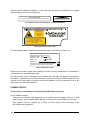
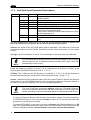
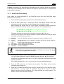
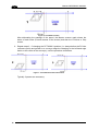
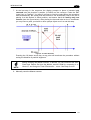
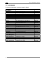
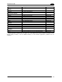
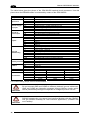
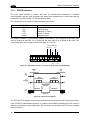
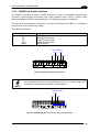
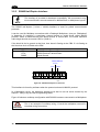
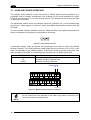
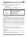
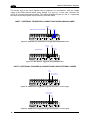
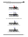
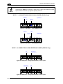
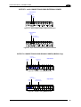
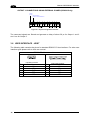
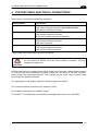
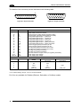
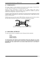
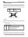
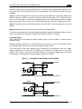
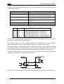
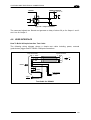
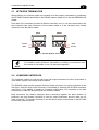
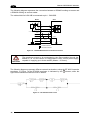
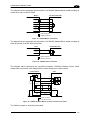
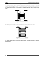
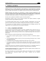
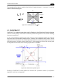
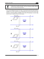
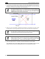
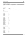
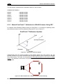
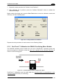
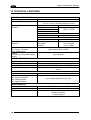
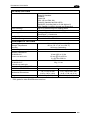
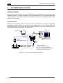
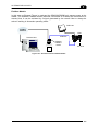
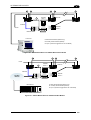
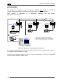
DS6400 REFERENCE MANUAL
4
Output 3 has different electrical features. It is a bi-directional solid state relay with built-in
current limit protection.
Output 3
Maximum Voltage
Collector Current (pulse)
± 100 V (Vext only)
300 mA Max. at 25°C (Ambient temperature)
240 mA Max. at 50°C (Ambient temperature)
200 mA Max. at 25°C (Ambient temperature)
150 mA Max. at 50°C (Ambient temperature)
6 – 15 Ω
> 500 Ω
< 1 µA
550 mW at 50°C (Ambient temperature)
Collector Current (continuous)
R on
R off
Off-State Leakage Current
Maximum Power Dissipation
Pin
8
22
11
12
16
17
Name
O1+
O1O2+
O2O3A
O3B
Function
Configurable digital output 1 – positive pin
Configurable digital output 1 – negative pin
Configurable digital output 2 – positive pin
Configurable digital output 2 – negative pin
Configurable digital output 3 – polarity insensitive
Configurable digital output 3 – polarity insensitive
The function of each output can be defined by the user (No Read, Right, Wrong, etc.). Refer to
the Genius™ Help On-Line for further details.
The output signals are fully programmable being determined by the configured
Activation/Deactivation events, Deactivation Timeout or a combination of the two.
By default, Output 1 is associated with the Complete Read event, which activates when all
the selected codes are correctly decoded, and Output 2 is associated with the No Read
event, which activates when the code signaled by the external trigger/PS is not decoded.
Output 3 can be assigned to the same events and it has the advantage of being polarity
insensitive. By default it is not assigned to any event.
DS6400
USER INTERFACE
Vext 30 Vdc max
+
-
Figure 68 – Output 1 and Output 2 Interface
When the load is powered by an external power supply, the voltage must be less than 30 V.
52