1
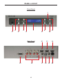
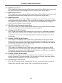
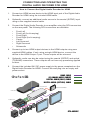
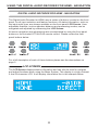
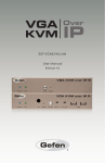
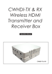
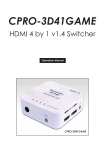
®
Digital Audio Decoder for
GTV-AUDDEC
User Manual
www.gefentv.com
ASKING FOR ASSISTANCE
Technical Support:
Telephone
Fax
(818) 772-9100
(800) 545-6900
(818) 772-9120
Technical Support Hours:
8:00 AM to 5:00 PM PST Monday thru Friday.
Write To:
Gefen, LLC
c/o Customer Service
20600 Nordhoff St
Chatsworth, CA 91311
www.gefentv.com
[email protected]
Notice
Gefen, LLC reserves the right to make changes in the hardware, packaging, and
any accompanying documentation without prior written notice.
Digital Audio Decoder for HDMI is a trademark of Gefen, LLC
Manufactured under license from Dolby Laboratories.
“Dolby”, “Pro Logic”, and the double-D symbol are trademarks of
Dolby Laboratories.
All trademarks are the property of their respective companies.
© 2012 Gefen, LLC. All rights reserved.
All trademarks are the property of their respective companies.
Rev A8
CONTENTS
1
Introduction
2
Operation Notes
3
Features
4
Panel Layout
5
Panel Descriptions
7
Connecting And Operating the Digital Audio Decoder For HDMI
8
GTV-AUD-IR Remote Description
10 Digital Audio Decoder for HDMI Remote Installation
11 Using The Digital Audio Decoder for HDMI - Navigation
12 Main Display
14 Operating the Menu System
19 Speaker Format Table
21 Bi-Amping
22 RS-232 Serial Control Interface
25 Specifications
26 Warranty
INTRODUCTION
Congratulations on your purchase of the Digital Audio Decoder for HDMI. Your
complete satisfaction is very important to us.
Gefen TV
Gefen TV is a unique product line catering to the growing needs for innovative
home theater solutions. We specialize in total integration for your home theater,
while also focusing on going above and beyond customer expectations to ensure
you get the most from your hardware. We invite you to explore our distinct
product line and hope that you find your solutions. Don’t see what you are looking
for here? Please call us so we can better assist you with your particular needs.
The Gefen TV Digital Audio Decoder for HDMI
The Gefen TV Digital Audio Decoder for HDMI decodes and processes
multi-channel surround sound audio for use with any amplified audio sound
system. Audio is extracted from an HDMI source while the video portion of the
signal is split into two identical HDMI outputs. When the audio is output via HDMI,
it will down mix Dolby Digitial 5.1 and multi-channel PCM to 2 channel PCM
audio. A conveniently placed optical and coaxial output are available to output
Dolby Digitial 5.1. All of this is available in a compact and attractive package that
can be placed in almost any location.
Stereo and multi-channel surround sound formats, with up to six discrete
channels of audio, are supported. Additional outputs for the front left and right
channel bi-amplification are available to satisfy even the most discerning
listeners. Advanced audio processing and setup features ensure an optimal
surround sound experience that is ready to be connected to your favorite
amplifier.
How It Works
HDMI or S/PDIF digital audio sources are connected to input connectors on
the Gefen TV Audio Decoder. To split HDMI, two HDMI-compliant displays are
connected to the Decoder’s HDMI outputs. To extract Surround Sound formatted
bitstream audio from A/V input sources to an external amplifier or receiver, run
analog audio or digital audio (TOSLINK/SPDIF) cables from the Decoder to
the amplifier or receiver’s input jacks. Power up all connected equipment, then
choose the input source using the IR remote control or the front panel buttons
and the LCD display. Up to 6 channels of Surround Sound audio will be heard on
audio output devices. Attached HDMI displays will show a vibrant, sharp hi-def
picture.
Note: The Gefen TV Audio Decoder features two additional analog audio
connectors for Bi-Amplification on the Front Left and Front Right channels.
The Gefen TV Audio Decoder outputs a maximum of discrete 6 audio channels. It
supports Dolby Digital and Dolby Pro Logic II.
1
OPERATION NOTES
READ THESE NOTES BEFORE INSTALLING OR
OPERATING THE DIGITAL AUDIO DECODER FOR HDMI
•
The Digital Audio Decoder for HDMI will down mix Dolby Digital 5.1 and
multi-channel PCM to 2 channel PCM on the HDMI output. This enables
the eight channel analog outputs to send a signal to the external amplifiers
and speakers. The HDMI carries a 2.0 PCM audio track that can be played
through your television
•
Dolby Digitial 5.1 through the coaxial or optical output with bitstream.
•
The Digital Audio Decoder for HDMI has 8 RCA outputs. A maximum of 6
discrete channels of audio can be output via these connectors. 2 connectors
are available for bi-amping the front left and right channels.
•
This product was intended for use with a separate audio amplifier. The RCA
output connectors on the rear panel will require the use of an audio amplifier
to produce adequate volume output.
•
This unit will support the following audio formats:
LPCM (up to 6 channels)
Dolby Digital (AC-3 up to 6 channels)
Dolby Pro Logic
Dolby Pro Logic II
•
This unit features multiple EDID (display information) modes which will
determine what audio formats can be used. For more information please see
page 17.
•
Dual HDMI outputs are featured and can be used to output two mirrored
signals.
•
This unit will accept sources that use Deep Color.
2
FEATURES
Features
•
Splits any HDMI input source to 2 mirrored HDMI outputs with HDCP passthrough
•
Extracts digital audio from an HDMI or S/PDIF source to 5.1 channels of
analog audio on RCA jacks
•
Outputs extracted digital audio to S/PDIF and TOSLINK connectors at up to
5.1 channels
•
LCD display and IR remote control make Decoder operation friendly
•
Six RCA jacks on the rear of the Decoder provide up to 5.1 channels of
analog L/R audio out
•
Two additional RCA jacks on the rear of the Decoder provide 2 channels of
analog audio for front channel bi-amping purposes
Package Includes
(1) GefenTV Audio Decoder
(1) IR Remote Control
(1) 6 ft. HDMI cable (M-M)
(1) 24V DC Power Supply
(1) User Manual
3
PANEL LAYOUT
Front Panel
1
3
2
5
4
7
6
Back Panel
15
9
11
8
16
4
12
17
10
13
18
14
19
20
PANEL DESCRIPTIONS
1
Power Status LED Indicator
This LED will indicate the current power state. When the LED is red, the unit is
in standby mode. When the LED is green, the unit is on.
2
Infrared (IR) Receiver
This IR receiver will accept commands from the included GTV-AUD-IR remote
control. This receiver requires line-of-sight between the unit and remote for
proper operation.
3
Mute / Right Button
This button will cycle between Mute-On and Mute-Off modes when not in the
Menu System. When the Mute-On mode is enabled, all audio output will be
ceased. While in the Menu System this button will cycle through available
options in the right direction when a feature has been selected for adjustment.
4
Input / Left Button
This button will toggle between the HDMI and Coaxial audio input sources
when not in the Menu System. When the HDMI source is selected, audio will
be extracted from the embedded audio within the incoming HDMI signal. When
the Coaxial source is selected, audio will be extracted from the incoming audio
source connected to the Coaxial (S/PDIF) input port. While in the Menu System
this button will cycle through available options in the left direction when a feature
has been selected for adjustment.
5
Volume Decrease / Down Button
This button is used to decrease the volume level of the audio outputs when
not in the Menu System. While in the Menu System this button will cycle down
through the current level’s options.
6
Volume Increase / Up Button
This button is used to increase the volume level of the audio outputs when not
in the Menu System. While in the Menu System this button will cycle up through
the current level’s options.
7
Main LCD Display
This display will show pertinent status information and will be used to make
adjustments to features in the Menu System.
8
Menu Button
This button will activate the Menu System which is where all adjustment and
settings will be made.
9
Mode / OK Button
This button will change the Processing Mode when not in the Menu System.
While in the Menu System this will be used as a confirmation button.
10 Exit Button
This button is used to exit the current menu level and return to the previous/
parent level. This button will exit the entire Menu System when on the top most
level.
11 Power Button
This button will toggle between the ON and STANDBY power states. An LED
status indicator will signify the current power state. A RED LED will be active
when the unit is in Standby power state. A GREEN LED will be active when the
unit is in the ON power state.
5
PANEL DESCRIPTIONS
12 HDMI Output Port 1
This output will accept a single HDMI output device. The HDMI input source will
be replicated and output through this port and the HDMI output port 2.
13 HDMI Output Port 2
This output will accept a single HDMI output device. The HDMI input source will
be replicated and output through this port and the HDMI output port 1.
14 HDMI Input Port
This input will accept a single HDMI source device. Audio in the source’s signal
will be extracted and processed. This input will be replicated and output through
the HDMI 1 & 2 ports. Audio from this source can be bypassed by using the
audio from the coaxial input connector.
15 RS-232 Serial Communications Port
This port is used to control functions and features using serial communications.
For more information on this feature please see page 22.
16 Analog Audio RCA Outputs
8 RCA type audio outputs are available for connection to a separate amplifier.
Up to 6 discrete channels can be utilized. 2 RCA audio output connectors are
available for front channel bi-amping purposes. Please see page 21 for more
information.
17 Coaxial (S/PDIF) Audio Output
This output is constantly active. Audio that is extracted from the input HDMI
source device or via the coaxial input is directly output through this connector.
Processing and features of the Digital Audio Decoder for HDMI are not applied
to the audio passing through this connector.
18 Optical (TOSLINK) Audio Output
This output is constantly active. Audio that is extracted from the input HDMI
source device or via the coaxial input is directly output through this connector.
Processing and features of the Digital Audio Decoder for HDMI are not applied
to the audio passing through this connector.
19 Coaxial (S/PDIF) Audio Input
A coaxial audio source can be connected and used as the main audio input
source if desired. Please be aware of the limitations of audio types and quality
which can be transported over this connector type.
20 24V DC Power Receptacle
This 24V DC power supply included with the unit connects to this receptacle.
Please only use the power supply that is included with this product.
6
CONNECTING AND OPERATING THE
DIGITAL AUDIO DECODER FOR HDMI
How to Connect the Digital Audio Decoder for HDMI
1.
Connect an HDMI source device to the HDMI input port of the Digital Audio
Decoder for HDMI using the included HDMI cable.
2.
Optionally, connect an additional audio source to the coaxial (S/PDIF) input
using a user supplied coaxial cable.
3.
Connect the Digital Audio Decoder to an amplifier using the RCA connectors
on the rear panel. The following RCA connectors are available:
•
•
•
•
•
•
•
•
Front Left
Front Left (for bi-amping)
Front RIght
Front Right (for bi-amping)
Center
Left Surround
Right Surround
Subwoofer
4.
Connect up to two HDMI output devices to the HDMI outputs using user
supplied HDMI cables. If only using a single HDMI device, connect this
device to the HDMI Output 1 port. These outputs will be mirrored.
5.
Optionally, audio can also be output using the coaxial (S/PDIF) and optical
(TOSLINK) connectors. These outputs will not have any processing applied
to them.
6.
Connect the included 24V DC power supply to the power receptacle on the
Digital Audio Decoder for HDMI. Connect the wall plug into an empty wall
power socket.
HDMI CABLE
(8) ANALOG AUDIO CABLES
DIGITAL AUDIO (COAX ) CABLE
DIGITAL AUDIO (OPTICAL) CABLE
®
GTV Audio Decoder
RS-232 Controller
Hi-Def Source
e
Audio Receiver
HD Display
SR
R
C
L
SL
Subwoofer
HD Display
7
GTV-AUDDEC
GTV-AUD-IR REMOTE DESCRIPTION
1
2
3
4
5
7
6
8
10
9
11
12
13
14
15
1
Power Off
This is a discrete power off button. Pressing this button will turn the Digital Audio
Decoder for HDMI off.
2
Power On
This is a discrete power on button. Pressing this button will turn the Digital Audio
Decoder for HDMI on.
3
Mode
This button functions the same as the Mode button on the front panel.
4
Menu
This button functions the same as the Menu button on the front panel.
5
Volume Up
This button will navigate up through options when using the Menu System and
will increase the volume when not in the Menu System.
6
Left
This button will navigate left when using the Menu System.
7
Right
This button will navigate right when using the Menu System.
8
Enter
This button will confirm options and changes made in the Menu System.
8
GTV-AUD-IR REMOTE DESCRIPTION
9
Exit
This button functions the same as the Exit button on the front panel.
10 Enhance
This button will cycle through the various enhancement modes. For a full
description of these modes please see page 17.
11 Volume Down
This button will navigate down through options when using the Menu System
and will increase the volume when not in the Menu System.
12 Mute
This button cycle between mute on and mute off modes. When mute is applied
there will not be any audio output.
13 Info/Test Tone
This button will display a series of information messages on the LCD screen
when pressed. When adjusting the Speaker Level, this button will activate a test
tone that is useful for adjusting the volume level of each speaker.
14 S/PDIF
This is a discrete button that will select the S/PDIF audio input source.
15 HDMI
This is a discrete button that will select the HDMI audio input source.
9
DIGITAL AUDIO DECODER FOR HDMI REMOTE INSTALLATION
To use the GTV-AUD-IR remote, remove the battery cover on the back of the remote
to reveal the battery compartment. Insert the included battery into the open battery
slot. The positive (+) side should be facing up. Ensure that both DIP (Dual Inline
Package) switches are in the OFF position. Replace the battery cover. The remote
ships with 2 batteries. One battery is needed for operation and the other battery is
complimentary.
Empty Battery Slot
DIP Switches
The DIP Switches above are used to set the IR Channel. Changing channels will
alleviate issues that may occur if the unit or remote control responds or interferes
with other non-Gefen equipment. This setting must match the IR Channel setting on
the unit. Please see page 18 for setting up the IR Channel on the unit.
Remote Channel 2:
Remote Channel 1:
1
2
1
2
1
2
Remote Channel 4:
Remote Channel 3:
1
2
10
USING THE DIGITAL AUDIO DECODER FOR HDMI - NAVIGATION
DIGITAL AUDIO DECODER FOR HDMI - NAVIGATION
The Digital Audio Decoder for HDMI uses a series of buttons, located on the front
panel, for all input selection and feature functions. All status information, such as
the input audio type, are always available on the front panel LCD Screen. User
adjustable features, such as speaker distance and processing modes, can be
navigated and adjusted by referencing the LCD Screen.
All menu navigation and adjustments are accomplished by using the front panel
buttons or the included GTV-AUD-IR remote control. Please review the front
panel buttons below.
For a full description of each of these buttons please see the descriptions on
page 5.
LCD SCREEN
The LCD Screen displays status information and can also be used to navigate
and adjust functions when using the Menu System. This display is a high contrast
2-line/16-character LCD. It will display information like in the example below.
11
MAIN DISPLAY
MAIN DISPLAY
The Main Screen will display useful information to the user. It displays the
currently selected input port and audio input format. The currently used output
format can also be displayed by pressing the ▼ button. Pressing the ◄ or ►
buttons while on this screen will have no effect. Please see below for the Main
Screen layout.
1
2
3
4
1
This section will display the currently selected audio input source.
2
This section will display the current volume level. The range is from
-60dB to +10dB
3
The section will display the current input audio format. This unit
will support LPCM (2-6) channels) and Dolby Digital (AC-3 up to 6
channels).
4
This section will display the current processing mode. Supported
modes are Direct, Stereo, Multi Channel Stereo, Mono, and Dolby PLII.
1 - INPUT SOURCE
This portion of the screen will display the currently selected input. The available
inputs and their labels are listed below:
LCD Display
Name
Actual Input
Location
HDMI
HDMI In
Rear Panel
SPDIF
Coax In
Rear Panel
To switch between audio input sources, use the front panel button labeled INPUT.
The IR remote control has discrete switching functions. To select the source
connected to the “Coax In” port, press the SPDIF button. To select the source
connected to the “HDMI In” port, press the HDMI button.
2 - VOLUME INDICATOR
This portion of the screen will display the current volume level. Volume control is
based on reference levels. 0.0dB on this unit is approximately 85dB (reference
level for dialog recorded in studios) with peaks of up to 105dB.
The maximum volume setting is +10dB. The minimum volume level is -60dB.
The default value is -30dB.
12
MAIN DISPLAY
3 - AUDIO FORMAT
This portion of the screen will display the current audio inputs format. Please use
the table below to determine what formats are accepted by each input type.
Input
Supported Audio Formats
LPCM
Supported Channels
6
HDMI
Dolby Digital
6
Dolby PLII
6
LPCM
2
Dolby Digital
6
Dolby PLII
6
Coaxial
4 - PROCESSING MODE
This portion of the screen will display the currently used processing mode.
Multiple processing modes are provided to enhance the audio experience.
The following processing modes are available:
•
Direct - This mode will playback audio without any processing (default).
•
Stereo - This mode will playback all audio at 2 channels. Multiple channel
audio will be down-mixed appropriately.
•
Multi Channel Stereo - The front right and left channels will be mixed and
also played back through the center channel speaker. This mode is only
available when using stereo sources. If this mode is selected and a multichannel source is detected, the mode will automatically switch to Direct
mode.
•
Mono - Audio from the front right channel will be played through both the
front right and front left speakers. If a center channel speaker is available,
the front right and front left channels will be played as normal but the center
will play a mix of the two audio channels.
•
Dolby Pro Logic II - Dolby Pro Logic II processes any high quality stereo
signal source into five separate full frequency channels. Dolby Pro Logic II
also decodes 5 channels from stereo signals encoded in traditional fourchannel Dolby Surround or five-channel Dolby Pro Logic II. This mode is
only available when using stereo sources. If this mode is selected and a
multi-channel source is detected, the mode will automatically switch to Direct
mode.
Note: Not all processing modes will be available for all input audio types. For
additional information on how which modes will affect various speaker setups and
audio formats, please see page 19.
13
OPERATING THE MENU SYSTEM
MENU SYSTEM
NAVIGATION
The Menu System will allow the user to configure features of the Digital Audio
Decoder for HDMI. The front panel buttons are used to navigate the Menu
System. Feature configuration can also be accomplished via the IR remote
control.
To enter the Menu System, press the MENU button located on the front panel.
The Main Menu will become available, The following menu options are available:
•
Speaker Size
This option will set the speaker size. The size of the speaker will determine
how lower frequency material is handled by each speaker.
•
Speaker Level
This option will allow the user to adjust the volume for each individual
speaker. The adjustment is designed to set each speaker’s volume for
equalizing the sound at the listening position.
•
Speaker Distance
This option will allow the user to adjust the distance value for each individual
speaker. The level adjustment will set delays necessary to create the proper
audio soundstage.
•
Tone Control
This option will allow the user to adjust the bass and treble levels.
•
Audio Setup
This option will allow the user to adjust the favorite processing and
enhancement modes.
•
Misc Setup
This option will allow the user to adjust the distance unit, EDID source, TV
System, and factory default reset.
•
Exit
This option will return the user to the Main Display screen.
Use the ▼ and ▲ buttons on the front panel to cycle between the options. To
select a menu option and proceed to it’s submenu, press the OK button.
14
OPERATING THE MENU SYSTEM
SPEAKER SIZE
This menu option will allow the user to select the speaker size to either SMALL
or LARGE. When a speaker size is set to SMALL, all frequencies below 80Hz
are automatically routed to the subwoofer channel. When a speaker size is set to
LARGE, all frequencies will be routed to the speaker.
All speakers except the front left and right channels have an option to disable the
use of that channel. If the center, rear surround, or subwoofer channels are not
going to be used these speakers should be set to the OFF setting. Source audio
that uses these channels will be properly mixed to the other available speakers.
Use the ▼ and ▲ buttons on the front panel to select the desired speaker output.
The following selections are available:
•
Front L/R - These settings will affect the front left and right channel outputs
(default is SMALL).
•
Center - These settings will affect the center channel outputs (default is
SMALL).
•
Surr L/R - These settings will affect the surround left and right channel
outputs (default is SMALL).
•
SUB - This should be set according to the use of a subwoofer (default is
ONSUB).
Use the ◄ and ► buttons on the front panel to change options for the selected
speaker.
When finished, press the ▼ or ▲ to move to another selection. Alternatively, the
user can press the OK button to immediately cycle to the next option.
To return to the previous menu, press the EXIT button. To exit the entire Menu
System, press the MENU button.
SPEAKER LEVEL
This menu option will allow the user to increase or decrease the volume of a
particular speaker. This feature is useful for equalizing the sound at the listening
position. By default, each speaker’s output is set at 00dB. The output can be
adjusted in 1dB increments between -10dB and +10dB.
Once a speaker is selected for adjustment, the INFO/TEST TONE button on the
IR remote control can be used to activate a test tone which will be heard through
the selected speaker output.
Use the ▼ and ▲ buttons on the front panel to select the desired speaker output.
The following selections are available:
•
Front L - These settings will affect the front left channel output (default is
+00dB).
•
Center - These settings will affect the center channel output (default is
+00dB).
15
OPERATING THE MENU SYSTEM
•
Front R - These settings will affect the front right channel output (default is
+00dB).
•
Surr R - These settings will affect the surround right channel output (default
is +00dB).
•
Surr L - These settings will affect the surround left channel output (default is
+00dB).
•
Sub - These settings will affect the subwoofer channel output (default is
+00dB).
Use the ◄ and ► buttons on the front panel to change options for the selected
speaker.
When finished, press the ▼ or ▲ to move to another selection. Alternately, the
user can press the OK button to immediately cycle to the next option.
To return to the previous menu, press the EXIT button. To exit the entire Menu
System, press the MENU button.
SPEAKER DISTANCE
This menu option will allow the user to set the distance of each speaker. This
feature is necessary for providing the proper audio delay when using the various
processing modes.
The distance unit can be viewed in either feet or meters. This option is set in the
Miscellaneous Setup menu. The distance for each speaker can be set in 1.5 feet
(0.5 meter) increments between 0 feet (0 meters) to 33 feet (10 meters).
Use the ▼ and ▲ buttons on the front panel to select the desired speaker output.
The following selections are available:
•
Front L - These settings will affect the front left channel (default is 3.0m).
•
Center - These settings will affect the center channel (default is 2.0m).
•
Front R - These settings will affect the front right channel (default is 3.0m).
•
Surr R - These settings will affect the surround right channel (default is
2.0m).
•
Surr L - These settings will affect the surround left channel (default is 2.0m).
•
Sub - These settings will affect the subwoofer channel (default is 3.0m).
Use the ◄ and ► buttons on the front panel to change options for the selected
speaker.
When finished, press the ▼ or ▲ to move to another selection. Alternately, the
user can press the OK button to immediately cycle to the next option.
To return to the previous menu, press the EXIT button. To exit the entire Menu
System, press the MENU button.
16
OPERATING THE MENU SYSTEM
TONE CONTROL
This menu option will allow the user to adjust the bass and treble settings. These
features were designed to allow the user to adjust the sound to their taste.
Both the treble and bass settings can be adjusted in 1db increments between
-12dB and +12dB .
Use the ▼ and ▲ buttons on the front panel to select either the treble or bass
option (default for both options are +00dB).
Use the ◄ and ► buttons on the front panel to change settings for the selected
option.
When finished, press the ▼ or ▲ to move to another selection. Alternately, the
user can press the OK button to immediately cycle to the next option.
To return to the previous menu, press the EXIT button. To exit the entire Menu
System, press the MENU button.
AUDIO SETUP
This menu option will allow the user to set favorite processing modes for both the
S/PDIF and HDMI inputs. Additionally, audio enhancement modes can also be
set in this menu option. The following features are available in this menu system:
•
SPDIF FAV PROC - This feature is used to set the default processing mode
for the S/PDIF input. Selectable processing modes can be found on page
14 (default is DIRECT).
•
HDMI FAV PROC - This feature is used to set the default processing mode
for the HDMI input. Selectable processing modes can be found on page 14
(default is DIRECT).
•
DRC - This feature will apply compression of loud sounds over a certain
threshold while quiet sounds remain untreated (default is OFF).
•
ENHA. - This feature is used to set an enhancement mode. The following
enhancement modes are available (default is OFF):
1.
Night+ Mode - This mode can be used to watch dynamic content at low
volume levels. This works by increasing the volume of quiet passages,
while decreasing the volume of load passages.
2.
Voice+ Mode - This mode will isolate and enhance dialog for clearer
sounding vocals.
3.
Volume+ Mode - This mode will equalize the volume level when listening
to a source that has large variation in volume level. (i.e. Television
broadcast and advertisement volume differences.)
Use the ▼ and ▲ buttons on the front panel to select the desired option.
Use the ◄ and ► buttons on the front panel to change the setting or the selected
option.
17
OPERATING THE MENU SYSTEM
When finished, press the ▼ or ▲ to move to another selection. Alternately, the
user can press the OK button to immediately cycle to the next option.
To return to the previous menu, press the EXIT button. To exit the entire Menu
System, press the MENU button.
MISCELLANEOUS SETUP
This menu option will allow the user to set miscellaneous settings. The following
options are in the menu:
•
DIST. UNIT - This will set the unit of measurement when using the
Speaker Distance option. The user can use either Feet or Meters as the
measurement unit (default is METER).
•
EDID ADJ. - This will control the location and type of EDID which will be
used to send to the HDMI source device. The following options are available:
•
•
•
INT - This option will use an internal EDID which will list all of the
supported audio and video formats that can be used with the Home
Theater Audio Processor.
•
EXT - This option will use the EDID from the HDMI device connected to
HDMI output 1.
•
MIX - This option will take video capabilities form the EDID of the
display connected to the display on HDMI input 1 and the audio
capabilities from the EDID of the Home Theater Audio Processor (this is
the default mode).
IR CHANNEL - This will set the IR channel that is used with the included
remote control. This setting must correspond with the setting on the IR
remote control. Please see page 10 for information on setting the IR channel
on the remote control.
•
1 - The unit will use IR channel 1 (this is the default setting)
•
2 - The unit will use IR channel 2
•
3 - The unit will use IR channel 3
•
4 - The unit will use IR channel 4
DEFAULT - This will return the Home Theater Audio Processor to its factory
default settings.
Use the ▼ and ▲ buttons on the front panel to select the desired option.
Use the ◄ and ► buttons on the front panel to change the setting or the selected
option.
When finished, press the ▼ or ▲ to move to another selection. Alternately, the
user can press the OK button to immediately cycle to the next option.
To return to the previous menu, press the EXIT button. To exit the entire Menu
System, press the MENU button.
18
SPEAKER FORMAT TABLE
SPEAKER AND FORMAT TABLE
Speaker Size
FL_R
PCM2ch /
Dolby_2ch
PCM2ch /
Dolby_2ch
Small
FavProcMode
CT
SL_R
SUB
SL_R
PLII(1)
Direct(2)
Stereo(3)
Mch
Stereo(4)
Mono(5)
Small
Small
onsub
Small
5.1ch
2.1ch
2.1ch
5.1ch
1.1ch
Small
Large
onsub
Large
5.1ch
2.1ch
2.1ch
5.1ch
1.1ch
Large
Small
onsub
Small
5.1ch
2.1ch
2.1ch
5.1ch
1.1ch
Large
Large
onsub
Large
5.1ch
2.1ch
2.1ch
5.1ch
1.1ch
off
Small
onsub
Small
4.1ch
2.1ch
2.1ch
4.1ch
2.1ch
off
Large
onsub
Large
4.1ch
2.1ch
2.1ch
4.1ch
2.1ch
Small
off
onsub
off
—
2.1ch
2.1ch
3.1ch
1.1ch
Large
off
onsub
off
—
2.1ch
2.1ch
3.1ch
1.1ch
off
off
onsub
off
—
2.1ch
2.1ch
2.1ch
2.1ch
Small
Small
onsub
Small
5.1ch
2ch
2ch
5.1ch
1.1ch
Small
Large
onsub
Large
5.1ch
2ch
2ch
5.1ch
1.1ch
Large
Small
onsub
Small
5.1ch
2ch
2ch
5.1ch
1.1ch
Large
Large
onsub
Large
5ch
2ch
2ch
5ch
1.1ch
off
Small
onsub
Small
4.1ch
2ch
2ch
4.1ch
2.1ch
off
Large
onsub
Large
4ch
2ch
2ch
4ch
2.1ch
Small
off
onsub
off
—
2ch
2ch
3.1ch
1.1ch
Large
off
onsub
off
—
2ch
2ch
3ch
1.1ch
off
off
onsub
off
—
2ch
2ch
2ch
2.1ch
Large
Small
Small
none
Small
5ch
2ch
2ch
5ch
1.0ch
Small
Large
none
Large
5ch
2ch
2ch
5ch
1.0ch
Large
Small
none
Small
5ch
2ch
2ch
5ch
1.0ch
Large
Large
none
Large
5ch
2ch
2ch
5ch
1.0ch
off
Small
none
Small
4ch
2ch
2ch
4ch
2ch
off
Large
none
Large
4ch
2ch
2ch
4ch
2ch
Small
off
none
off
—
2ch
2ch
3ch
1.0ch
Large
off
none
off
—
2ch
2ch
3ch
1.0ch
off
off
none
off
—
2ch
2ch
2ch
2ch
19
SPEAKER FORMAT TABLE
SPEAKER AND FORMAT TABLE
Speaker Size
FL_R
PCM5.1ch /
AC3_5.1ch
PCM5.1ch /
AC3_5.1ch
Small
FavProcMode
CT
SL_R
SUB
SL_R
PLII(1)
Direct(2)
Stereo(3)
Mch
Stereo(4)
Mono(5)
Small
Small
onsub
Small
—
5.1ch
2.1ch
5.1ch
1.1ch
Small
Large
onsub
Large
—
5.1ch
2.1ch
5.1ch
1.1ch
Large
Small
onsub
Small
—
5.1ch
2.1ch
5.1ch
1.1ch
Large
Large
onsub
Large
—
5.1ch
2.1ch
5.1ch
1.1ch
off
Small
onsub
Small
—
4.1ch
2.1ch
4.1ch
2.1ch
off
Large
onsub
Large
—
4.1ch
2.1ch
4.1ch
2.1ch
Small
off
onsub
off
—
3.1ch
2.1ch
3.1ch
1.1ch
Large
off
onsub
off
—
3.1ch
2.1ch
3.1ch
1.1ch
off
off
onsub
off
—
2.1ch
2.1ch
2.1ch
2.1ch
Small
Small
onsub
Small
—
5.1ch
2.1ch
5.1ch
1.1ch
Small
Large
onsub
Large
—
5.1ch
2.1ch
5.1ch
1.1ch
Large
Small
onsub
Small
—
5.1ch
2.1ch
5.1ch
1.1ch
Large
Large
onsub
Large
—
5.1ch
2.1ch
5.1ch
1.1ch
off
Small
onsub
Small
—
4.1ch
2.1ch
4.1ch
2.1ch
off
Large
onsub
Large
—
4.1ch
2.1ch
4.1ch
2.1ch
Small
off
onsub
off
—
3.1ch
2.1ch
3.1ch
1.1ch
Large
off
onsub
off
—
3.1ch
2.1ch
3.1ch
1.1ch
off
off
onsub
off
—
2.1ch
2.1ch
2.1ch
2.1ch
Large
Small
Small
none
Small
—
5ch
2ch
5ch
1.0ch
Small
Large
none
Large
—
5ch
2ch
5ch
1.0ch
Large
Small
none
Small
—
5ch
2ch
5ch
1.0ch
Large
Large
none
Large
—
5ch
2ch
5ch
1.0ch
off
Small
none
Small
—
4ch
2ch
4ch
2ch
off
Large
none
Large
—
4ch
2ch
4ch
2ch
Small
off
none
off
—
3ch
2ch
3ch
1.0ch
Large
off
none
off
—
3ch
2ch
3ch
1.0ch
off
off
none
off
—
2ch
2ch
2ch
2ch
20
BI-AMPING
BI-AMPING
The Digital Audio Decoder for HDMI features 2 additional outputs for bi-amping
the front right and left audio channels. These outputs were intended to supply an
additional set of front right and left audio channels for use with an amplifier and
bi-ampable speaker. Please refer to your amplifier and speaker manual for proper
bi-amping connection procedures.
21
RS-232 SERIAL CONTROL INTERFACE
54321
12345
9876
6789
Only Pins 2 (RX), 3 (TX), and 5 (Ground) are used on the RS-232 serial interface
RS232 Settings
Bits per second ................................................................................................. 19200
Data bits .................................................................................................................... 8
Parity .................................................................................................................. None
Stop bits .....................................................................................................................1
Flow Control ....................................................................................................... None
22
RS-232 SERIAL CONTROL INTERFACE
RS-232 Command Table
Command Code
Response
Description
POWER 0
> POWER OFF
POWER OFF
POWER 1
> POWER ON
POWER ON
VOL +10~-60
> VOL +10~-60
Audio volume adjust from maximum to
minimum
VOL +
> VOL +10~-60
Increase audio by 1
VOL -
> VOL +10~-60
Decrease audio by 1
MODE 0
> PL II
Audio FAV PROC setup to Dolby Pro Logic
II mode
MODE 1
> DIRECT
Audio FAV PROC setup to DIRECT mode
[Default:DIRECT]
MODE 2
> STEREO
Audio FAV PROC setup to STEREO mode
MODE 3
> MCH
Audio FAV PROC setup to MCH mode
MODE 4
> MONO
Audio FAV PROC setup to MONO mode
ENHA 0
> ENHA NIGHT+
Audio ENHANCE effect NIGHT+
ENHA 1
> ENHA VOICE+
Audio ENHANCE effect VOICE+
ENHA 2
> ENHA VOLUME+
Audio ENHANCE effect VOLUME+
ENHA 3
> ENHA OFF
Audio ENHANCE effect OFF [Default:OFF]
TESTN 0
> NOISE FL
Generate pink noise for adjusting the Front
Left speaker Audio volume
TESTN 1
> NOISE CT
Generate pink noise for adjusting the
Center speaker Audio volume
TESTN 2
> NOISE FR
Generate pink noise for adjusting the Front
Right speaker Audio volume
TESTN 3
> NOISE SR
Generate pink noise for adjusting the
Surround Right speaker Audio volume
TESTN 4
> NOISE SL
Generate pink noise for adjusting the
Surround Left speaker Audio volume
TESTN 5
> NOISE SUB
Generate pink noise for adjusting the
Subwoofer speaker Audio volume
MUTE 0
> MUTE OFF
Audio MUTE OFF [Default:OFF]
MUTE 1
> MUTE ON
Audio MUTE ON
INPUT 0
> INPUT SPDIF
Audio input switch to SPDIF mode
INPUT 1
> INPUT HDMI
Audio input switch to HDMI mode
FIRMWARE ?
> FIRMWARE 1.XX
Show firmware version format is 1.XX
23
RS-232 SERIAL CONTROL INTERFACE
Command Code
Response
Description
SIZEFLR 0
OK
Front speaker Small
SIZEFLR 1
OK
Front speaker Large
SIZEC 0
OK
Center speaker Small
SIZEC 1
OK
Center speaker Large
SIZEC 2
OK
Center speaker Off
SIZELR 0
OK
Surround speaker Small
SIZELR 1
OK
Surround speaker Large
SIZELR 2
OK
Surround speaker Off
SUB 0
OK
Subwoofer Off
SUB 1
OK
Subwoofer On
INFO ?
>1234
Read audio information (1: Source, 2: Type,
3: CH, 4: Rate)
24
SPECIFICATIONS
Digital Video Amplifier Bandwidth ............................................................ 225 MHz
Input DDC Signal ......................................................................... 5 Volts p-p (TTL)
Single Link Range .......................................... 1080p/1920 x 1200 max. resolution
Digital Audio Input ..................................................................... 1 x S/PDIF coaxial
HDMI Input ...................................................................... 1 x HDMI Female 19-pin
HDMI Outputs ................................................................. 2 x HDMI Female 19-pin
Digital Audio Output .................................................................. 1 x S/PDIF coaxial
Digital Audio Output ............................................................... 1 x TOSLINK optical
Analog Audio Outputs ................................................................................... 8 total
(6 analog audio RCA jacks + 2 additional RCA jacks for Bi-Amp)
Supported Audio Formats:
Dolby Digital 5.1 (AC3), LPCM HDMI direct (up to 6 ch.)
Audio Processing ....................................................................... Dolby Pro Logic II
Signal To Noise Ratio ..................................... >90dB (20Hz-20kHz A weight filter)
THD+N .............................................................. < 0.1% at 1kHz at reference level
Frequency Response ...................................................... < +/- 0.5dB 20Hz-20kHz
Power Supply ............................................................................................ 24V DC
Dimensions .......................................................................... 6.9”W x 2.1”H x 6.9”D
Shipping Weight ............................................................................................ 6 lbs.
25
WARRANTY
Gefen warrants the equipment it manufactures to be free from defects in material
and workmanship.
If equipment fails because of such defects and Gefen is notified within two (2)
years from the date of shipment, Gefen will, at its option, repair or replace the
equipment, provided that the equipment has not been subjected to mechanical,
electrical, or other abuse or modifications. Equipment that fails under conditions
other than those covered will be repaired at the current price of parts and labor in
effect at the time of repair. Such repairs are warranted for ninety (90) days from
the day of reshipment to the Buyer.
This warranty is in lieu of all other warranties expressed or implied, including
without limitation, any implied warranty or merchantability or fitness for any
particular purpose, all of which are expressly disclaimed.
1.
Proof of sale may be required in order to claim warranty.
2.
Customers outside the US are responsible for shipping charges to and from
Gefen.
3.
Copper cables are limited to a 30 day warranty and cables must be in their
original condition.
The information in this manual has been carefully checked and is believed to
be accurate. However, Gefen assumes no responsibility for any inaccuracies
that may be contained in this manual. In no event will Gefen be liable for
direct, indirect, special, incidental, or consequential damages resulting from
any defect or omission in this manual, even if advised of the possibility of such
damages. The technical information contained herein regarding the features and
specifications is subject to change without notice.
For the latest warranty coverage information, refer to the Warranty and Return
Policy under the Support section of the Gefen Web site at www.gefen.com.
PRODUCT REGISTRATION
Please register your product online by visiting the Register Product page
under the Support section of the Gefen Web site.
26
Rev A8
20600 Nordhoff St., Chatsworth CA 91311
1-800-545-6900
818-772-9100
www.gefen.com
Pb
This product uses UL listed power supplies.
fax: 818-772-9120
[email protected]