1
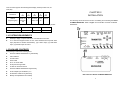
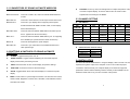
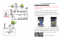
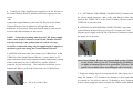
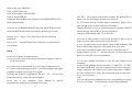
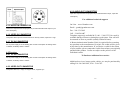
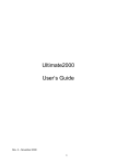
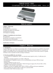
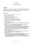
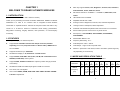
CHAPTER 1
WELCOME TO GRAND ULTIMATE WIRELESS
!
Menu key supports Freeze , Size, Brightness, Contrast, Hue, Saturation,
Video Standard, Flicker, OSD color, Reset.
!
1.1 INTRODUCTION
DIP Switch controls for: CHANNEL 1~ CHANNEL 4, RGB enable, YUV
enable.
(PC/iMAC DV to TV converter with 2.4Ghz AV Sender)
!
LED indicator PAL & POWER.
Thank you for purchasing the Grand ULTIMATE WIRELESS. GRAND ULTIMATE
!
Adjustable H-SIZE and V-SIZE.
WIRELESS is a VGA to TV converter with an integrated 2.4GHz Wireless
!
64 stage control of: Brightness, Contrast, Hue, Saturation adjustment.
Transmitter & separate Receiver. Transmit the computer’s video and audio to any
!
16 stage control of: Sharpness, Flicker adjustment.
remote TV. It is ideal for Internet or DVD/VCD movie viewing, presentations,
!
Automatic COLOR BAR test pattern when VGA source is not connected.
baby/patient monitoring, burglary detection, theft prevention, or home/company
!
Stereo Audio input from sound card or any audio device.
monitoring.
!
RF frequency : CH1=2414MHz, CH2=2432MHz, CH3=2450MHz,
CH4=2468MHz.
1.2 FEATURES
!
Demodulation Method : FM.
!
Plug and Display: No software required.
!
Frequency Generating : P.L.L..
!
Supports four selectable channels and multiple receivers (available
!
Audio Response : 20Hz ~ 20kHz.
separately) Transmits (Composite Video and Stereo Audio), ISM Band from
!
Video Output : 1Vpp/ 75 ohm composite video.
2414~2468Mhz.
!
Distance : Open area is 100 meters, indoor is 30 meters. (Actual range may
!
Supports resolutions up to 1600x1200.
!
Simultaneous display on TV, Remote TV and VGA monitor.
!
Supports NTSC, NTSC-EIAJ PAL-N, PAL, PAL-M, PAL-combination-N and
SECAM (via RGB OUT) video systems.
!
vary depending on environment)
1.3 MODE AND RESOLUTION TABLE
This converter supports the following VGA display modes:
Supports CVBS, S-VIDEO or RGB video outputs by switch change (via wired
Resolution
connections).
!
Simultaneous RGB and CVBS output signal on RGB out connector.
!
True 24 bit, true color digitizer.
!
User controls: MENU, ZOOM, FINE TUNE SAVE VIDEO SOURCE POWER
Vertical
Frequency
(Hz)
720
x
400
70
640
x
480
800
x
600
1024
x
768
60, 70, 56, 60, 60, 70, 60, 70,
72, 75
72, 75, 70, 72, 72,
85, 100, 75, 85, 75
100
120
& Position adjustments.
1
1152
x
864
2
1280
x
960
1280
x
1024
1600
x
1200
60
60
60
This converter supports the following MAC display modes:(for MAC G4, G4
Cube,G3)
640
x
480
832
x
624
60,66,72,7
5,85,100,
120
75
Resolution
Vertical
Frequency(Hz)
1024
X
768
1152
X
864
56,60,72, 60,70,
75,85, 100 75
60,70
800
X
600
CHAPTER 2
INSTALLATION
The following section shows the function of installing and controlling the Grand
ULTIMATE WIRELESS. Refer to Figure 1 for the Outline of Grand ULTIMATE
This converter fully supports APPLE iMac and iMAC DV computer display modes
Resolution
640x480
800x600
1024x768
Vertical frequency (Hz)
117
95
75
WIRELESS.
1.4 SYSTEM REQUIREMENTS
!
Desktop or laptop computer with HD15 VGA standard connection.
!
TV or VCR that supports NTSC or PAL video standard with composite video
input (required for wireless transmission), (or) S-Video input, (or) RGB video
input, (or) SCART input connector.
1.5 PACKAGE CONTENTS
This package contains the following items:
!
Grand ULTIMATE WIRELESS Tx [Transmitter]
!
User‘s Manual
!
S-Video cable
!
Video cable
!
PC to TV Audio cable
!
Audio pass-through cable
!
H cable for VGA Connection
!
Grand ULTIMATE WIRELESS Rx [Receiver]
!
Power adapter (DC 6V/800mA ) x 2
!
Audio/Video Cable for Rx [Receiver]
!
Battery Pack (Batteries not included)
3
FIG.1 Outline of Grand ULTIMATE WIRELESS
4
2.1 CONNECTORS OF GRAND ULTIMATE WIRELESS
!
POSITION : Press up, down, left and right button to adjust the position of the
converted computer display. These four buttons also are used to make
!
SCAN CNVTR : Connects H cable to PC, Grand ULTIMATE WIRELESS and
adjustments to the settings in the MENU.
monitor.
!
!
AUDIO IN:
Connects to sound device or audio output of DVD/ VCD /VCR.
2.3 CHANNEL SETTING
RGB OUT:
Connects to your display device supporting the European
!
SCART Standard with RGB to SCART cable, or other display
SW1
device with RGB input.
!
VIDEO OUT:
DIP SWITCH:
SW2
SW3
SW4
SW5
SW6
DOWN (ON)
CHANNEL 1
DOWN(ON)
Connects Grand ULTIMATE WIRELESS to the Video input of
DESCRIPTION
CHANNEL 2
DOWN(ON)
CHANNEL 3
the TV. (Optional for wired connections)
!
DOWN(ON)
S-OUT :
Connects Grand ULTIMATE WIRELESS to your TV supporting
DOWN(ON)
the S-VIDEO input. (Recommend for wired connections)
!
DC IN :
Connects with supplied AC power adapter.
!
VIDEO IN:
Connects to your video device such DVD/VCR/Camera for
2.2 BUTTONS & SWITCHES OF GRAND ULTIMATE
WIRELESS
!
POWER : Toggle between power on & off.
!
VIDEO SOURCE : Toggles between displaying the converted computer
YUV OUTPUT
DOWN(ON)
RGB OUTPUT
NOTE: RGB OUTPUT and YUV OUTPUT can not be enabled at the same time
!
video pass-through.
CHANNEL 4
2.4GHz Receiver Channel seting:
SWITCH 1
SWITCH 2
SWITCH 3
SWITCH 4
CHANNEL 1
CHANNEL 2
CHANNEL 3
CHANNEL 4
2.4 INSTALLATION
display and the video pass-through source.
The Grand ULTIMATE WIRELESS is a “Plug and Display” video converter. The only
!
SAVE: Press this button to save current display and position settings.
!
FINE TUNE : Press this to fine-tune the video image.
!
ZOOM : Toggle between Zoom and Normal display for converted computer
requirement to get the output of the computer on the TV is to make the proper
connections and ensure that your computer display is set within the supported
parameters. Please read the following sections carefully for the installation of the
hardware. Please refer to Fig.2 for and overview of the process.
display.
!
MENU : Press button to cycle through the functions. The functions are: Freeze,
HSIZE, VSIZE, Brightness, Contrast, Hue, Saturation, Video Standard, Flicker
and OSD color, Reset.
5
6
Fig.2 Grand ULTIMATE WIRELESS Installation
2.5 STEP BY STEP CONNECTIONS
IMPORTANT! Turn your computer OFF before connecting the
Ultimate Wireless!
1. Connect the end of the H Cable that is RED to the port on the
Ultimate Wireless labeled SCAN CNVTR (which is also red).
2. Connect the end of the H cable that is BLUE to the CRT port on
the back of your laptop or desktop PC. On a desktop, you may need
to first unplug the monitor.
Fig. 3 – Laptop Connection
Fig. 4 – Desktop with Monitor
3. Connect one end of the audio pass-through cable to the AUDIO
IN port on the Grand Ultimate Wireless. Connect the other end to the
LINE OUT or SPEAKER OUT of your sound card. On a desktop you
may first have to disconnect your existing computer speakers.
Fig. 5 – Audio Pass-Through Cable
7
8
4. Connect one of the supplied power supplies to the DC IN port on
the Grand Ultimate Wireless and then connect the supply to a wall
outlet.
-ORConnect the supplied battery pack to the DC IN port on the Grand
Ultimate Wireless. Four AA batteries will typically run the
transmitter for four hours. Please note that the battery pack may be
used on either the transmitter or the receiver.
NOTE: Connecting anything other than a 6V DC power supply
with a center positive connector to the Grand Ultimate Wireless
will cause damage to the product and will void the warranty.
6. A. [OPTIONAL FOR WIRED CONNECTIONS] Connect either
the yellow-ended composite video or the solid black S-video cable
between the VIDEO OUT of the Grand Ultimate Wireless and the
VIDEO IN of your television.
B. [OPTIONAL FOR WIRELESS CONNECTIONS] Connect the
Grand Ultimate Wireless Receiver to your TV using the AV Cable.
Plug the power supply to the DC IN of the Receiver and then connect
the supply to a wall outlet.
GrandTec recommends using only the supplied power supplies or
the battery pack when using the Grand Ultimate Wireless.
5. [OPTIONAL]Connect the video output of a VCR/DVD/etc. to the
VIDEO IN of the Grand Ultimate Wireless. Connect the PC to TV
audio cable between the audio outputs (normally indicated by red and
white connections) of your VCR/DVD/etc. and the LINE IN
connector on your sound card. This connection will allow you to
transmit the audio as well as the video from your VCR/DVD/etc.
Figure B
Fig. 6 – PC to TV Audio Cable
9
Fig. 7 – AV Cable
Note: Grand Ultimate Wireless also supports high quality S-VIDEO
via the S-video cable. If your TV or VCR supports S-VIDEO IN,
we highly recommend you use it to get the best TV picture. This
option is not available when transmitting the video wirelessly.
7. Toggle the display input to correspond with the video input you are
using. For instance, a TV defaults to the antenna or cable input when
it is turned on. You will see either a TV channel or snow. Using the
remote control toggle the input to display the VIDEO rather than the
10
antenna/cable. Each TV varies slightly, so you may need to refer to
your TV's user's manual for further assistance.
tape after a few moments to test that it is recording.
8. If you are experiencing any distortion or interference in the
wireless transmission, change the transmission channels. Using a
paperclip, change the switches on both the transmitter and the
receiver so that they are on the same channel. Only one switch
CHAPTER 3
should be DOWN on each and the switch that is DOWN indicates
which channel is in use.
The following are problems that might arise when using the PC to
TV converter, and possible solutions to them.
9. If your TV does not have a VIDEO input, you may connect
through a VCR's VIDEO IN. Note: Since virtually every VCR is
Things to Check :
1. The input on the display (TV, projector, etc.) is not properly set. If
your display has multiple video inputs, then you have to toggle the
inputs to display the one you need. Typically this is done via the
different, please refer to your VCR User's Manual for exact
instructions for recording an external video source.
To connect the Grand Ultimate Wireless to a VCR for recording,
follow these steps:
1. Using either the RCA or the S-video (recommended) cable,
connect from the video out on the Grand Ultimate Wireless to the
Video IN on the VCR
2. Using either an RCA or a 75 Ohm coaxial cable connect from the
Video OUT on the VCR to the Video IN on the TV
3. Set the TV/VCR switch on the VCR to "VCR"
4. Set the TV to display the video input signal (Refer to TV's User's
manual for instruction on displaying an external video source)
5. You should be able to see the converted computer display on the
TV
6. Insert a blank tape into the VCR and press "RECORD". Stop the
11
Technical Tips
remote.
2. The TV looks fine during boot-up but once the PC enters Windows
all I see is black and white horizontal wavy lines: The display
adapter (video card) is set to a refresh rate not supported by the
converter. Refer to the MODE and RESOLUTION Table in the
beginning of this user’s manual.
The following procedure is required on most typical systems (Note:
your PC may require a different procedure. Please refer to your PCs
documentation for how to adjust the refresh rate for further
information):
Start Menu -> Settings -> Control Panel
12
Click on the icon "DISPLAY".
Click on SETTINGS tab.
Click on the button "ADVANCED".
Click on ADAPTER tab.
Change the Refresh Rate from Optimal to ADAPTER DEFAULT or
60Hz and click apply.
If you do not see REFRESH RATE under the ADAPTER tab, click
on the MONITOR tab and be sure that the monitor type is set to:
Desktop users: Super VGA 1024x768 (or desired maximum
resolution)
Laptop users: Laptop Display Panel 1024x768 (or equivalent for
your system)
The "Fn" + "Fx" toggles between three settings. By default, the LCS
panel is on. The first toggle attempts to power both
the LCD panel and the external signal. Sometimes, laptops do not
have enough power to show both the LCD and the
Ultimate Wireless, so only a scrambled signal is viewable on the TV.
The third toggle turn off the LCD panel and shows
only the external display (the TV, in this case).
Q: I have an older model of a television. Would I be able to use my
video converter with a television as old as this one?
A: Yes, you may need a special adapter called an RF modulator. This
device converts the composite video signal from your video
converter to an Antenna signal, which can be viewed on your TV
using Channel 3 or 4 or 13. You may also use a VCR in some cases.
Q&A
Q: How can I enhance the display quality?
A: You can usually decrease the contrast and increase brightness control to
get the better picture.
Q: I connect using a NOTEBOOK PC, but no output is displayed on TV.
A: To get a converted image on the TV, you must configure the laptop
computer to display an external VGA signal.
Typically, this is done by toggling the "Fn" key + "F1", "F2", etc. The
actual function key varies with each computer.
Please refer to your computer's User's Manual for specific
instructions for displaying an external VGA signal.
13
Refer to section D3 for more information.
Q: Can I use multiple televisions to view the same image from my
computer?
A: Yes, Grand Ultimate Wireless provides 1 CVBS OUT, 1 S-VHS
OUT and 1 RGB OUT. You may connect one television to the next
using a composite video cable or an S-Video between the “VIDEO
IN” and “VIDEO OUT” ports. We recommend using no more than
five or six televisions.
-ORYes, you may purchase additional receivers and transmit to as many
TVs as are in range. For information on purchasing additional
14
receivers, please call 214-366-3496.
4.1.2 RGB OUT CONNECTOR
RGB OUT is a 9-pin mini-DIN type female connector. It can output RGB and
Composite VIDEO signals. Detailed description is below: This connector cannot
CHAPTER 4
TECHNICAL SPECIFICATIONS
work with S-OUT and VIDEO OUT simultaneous. This connector is very useful for
European TVs with SCART connectors.
Pin No.
4.1 Transmitter
1
Blue output, 0.7Vpp, 75 ohms
2
RGB enable, +12V output to enable Europe TV
4.1.1 SCAN CNVTR CONNECTOR
Analog RGB and SYNC signal from 15 pin VGA output port of PC or Notebook PC,
and output SYNC signal to monitor.
Pin No.
1
2
3
4
5
6
7
8
9
10
11
12
13
14
15
Signal Description
RED IN, 0.7Vpp ± 0.1Vpp, 75 ohms, from PC
GREEN IN, 0.7Vpp ± 0.1Vpp, 75 ohms, from
PC
BLUE IN, 0.7Vpp ± 0.1Vpp, 75 ohms, from PC
No connection
Monitor Sense, TTL level, active low
Ground
Ground
Ground
No connection
Ground
HSYNC OUT, TTL level, buffered HSYNC IN,
to monitor
VSYNC OUT, TTL level, buffered VSYNC IN,
to monitor
HSYNC IN, TTL level
VSYNC IN, TTL level
No connection
Signal Description
RGB input.
3
Green output, 0.7Vpp, 75 ohms s
4
Composite VIDEO, negative sync, 1Vpp
5
No connection
6
No connection
7
Red output, 0.7Vpp, 75 ohms
8
Audio output, left channel, 1 Vrms
9
Audio output, Right channel, 1 Vrms
Remark: Case is connected to ground
4.1.3 VIDEO OUT CONNECTOR
Composite video out, 1.0Vpp ± 0.2Vpp 75 ohms, negative sync.
4.1.4 S-VIDEO OUT CONNECTOR
S-OUT connector is a 4-pin mini-DIN connector.
Remark: Case is connected to ground
15
16
4.2.3 AUDIO OUT CONNECTOR
Input with computer Audio output (line out) or DVD/VCR/VCD output , Input with
1Vrms(max)
For additional technical support:
4.1.5 AUDIO IN CONNECTOR
Connect to computer audio output (line out) or DVD/VCR/VCD audio output. Input
On-Line – www.Grandtec.com
Email – [email protected]
Fax – 214-351-3862
with 1Vrms(max)
4.1.6 VIDEO IN CONNECTOR
Composite video input from DVD/VCR/VCD or security camera, Input level: 1 Vpp
4.1.7 DC IN CONNECTOR
DC 6V power supply or DC 6V battery pack. Power Consumption at working status
is 480mA, at standby status is 130mA.
4.2 Receiver
4.2.1 DC IN CONNECTOR
Call – 214-956-0447
Telephone support is available M-F, 9:00 – 5:00 CST. Voice-mail is
available during off hours or during busy peak times. Your call will
be returned as soon as possible (usually within 24 hours).
A Return Authorization Number (RA#) is required before returning
any products to the manufacturer for repair. No credits will be given
at any time by the manufacturer. If you desire a credit for the return
of your product, please contact the retailer from whom you originally
purchased the product. Credits are subject to the policies of the
individual retailer.
To Purchase Additional Accessories:
DC 6V power supply or DC 6V battery pack. Power Consumption at working status
is 480mA, at standby status is 130mA.
Additional receivers, battery packs, cables, etc. may be purchased by
calling 214-366-3496 M-F, 9:00 – 5:00 CST.
4.2.2 VIDEO OUT CONNECTOR
Composite video out, 1.0Vpp ± 0.2Vpp 75 ohms, negative sync.
17
18
Warranty
We warrant the Grand Ultimate Wireless shall, for a period of one year from the
date of purchase, be free of any defect in material and workmanship and that it will
perform in accordance with specifications. The sole obligation of this warranty
shall be to either repair or replace at our expense the product, at manufacturer’s
option. The original sales receipt must be supplied for warranty repair.
There are no warranties except as stated. There are no warranties expressed or
implied, including, but not limited to, the implied warranties of merchantability and
of fitness for a particular purpose. In no event shall we be liable for consequential,
incidental, or special damages, including, but not limited to, damages or loss of
data, profits or goodwill.
Products that have been subject to abuse, misuse, vandalism, accident, alteration,
neglect, unauthorized repair or improper installation will not be covered by
warranty.
19