1
MODE 3.1 Installation Instructions
Page 8
MODE BASE FEATURES
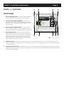
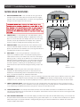
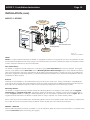
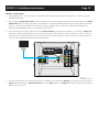
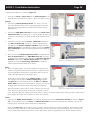
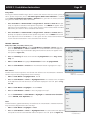
1. BASE ALIGNMENT TAB - Two small tabs on the right side of
the Base fit into two small indents on the left side of an adjoining Base when using multiple Bases. The Bases are magnetically
charged and lock together for convenience.
12V DC 1 AMP
Adaptor Port
Aux. Input
USB
2
3
4
5
1
1
CAUTION: MODE Base magnets are fairly strong and
should not be mounted directly on or near CRTs or Plasma displays. Care should also be taken to keep magnetic
media such as audio and video tapes, credit cards, etc.
away from the MODE Base units as important media may
be lost!!!
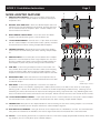
2. POWER JACK - 2.1mm coaxial jack. The MODE Base is powered directly from the MODE Adapter in applications where the
Base is less than 250’ from the Adapter. For wire runs over 250’,
the Base can be up to 500’ from the Adapter with a SpeakerCraft PS-2.0 Power Supply connected directly to the Base.
3. ADAPTER PORT - RJ45 jack connects to the iPod Base Terminal on the MODE Adapter via CAT5. This connection provides
power and control to the iPod/Base and sends digital audio and
metadata from the Base to the Adapter.
4. AUX INPUT - 3.5mm mini jack provides a stereo line level
input for an additional source. This could be anything from a
cable/satellite receiver, to an XM or Sirius Tuner or a DVD player
allowing up to 12 Sources on an MZC-66 or 14 Sources on an
MZC-88 (including on-board tuners). This connection will allow
the local source audio to be played through the MZC amplifier
and zone speakers. Switching to and controlling the sources
connected to this input must be configured during setup in EZTools.
6
8 7
7
1
1
9
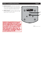
Figure 4
MODE Base Features
5. USB PORT - USB mini B jack allows connection directly to a
computer for downloading content to an iPod seated in the
MODE Base. Downloading content would follow normal procedures. See iPod instructions for additional information.
6. BASE DOCK - This opening in the Base is where an iPod gets connected to an MZC system. Different sized inserts allow
adapting the various different models of iPods to the Base. NOTE: Never connect an iPod without an insert in place.
Without an insert, the iPod may not connect properly and there is potential for damage to the iPod, the Base or both.
7. INSERT CAPTURE SLOTS - Each of the inserts has two T-shaped posts that slide into these slots to secure the insert
for the specific iPod being used. If it becomes necessary to change inserts, carefully push the T-shaped posts of another
insert up through the bottom of the Base and pull the seated insert out from the top.
8. iPOD CONNECTOR - This multi-pin connector connects to the iPod Dock Connector on the bottom of an iPod. Carefully push the iPod down on this connector to send power and control to the iPod and have the iPod send digital audio
and metadata to the system.
9. MZC SOURCE INDICATOR - This blue LED displays the MZC Source Input for the MODE Base being used. An iPod can
be moved from room to room and will identify to the system which room it is in. The Base will be dedicated to a specific
MZC Source Input. The Source Indicator is configured by pressing the Source ID Button on the bottom of the Base to
match the MZC Source Input.